2006 SUZUKI SWIFT Oil filter part
[x] Cancel search: Oil filter partPage 9 of 1496
Downloaded from www.Manualslib.com manuals search engine Precautions: 00-4
General PrecautionsS7RS0B0000002
The WARNING and CAUTION describe some general
precautions that you should observe when servicing a
vehicle. These general precautions apply to many of the
service procedures, and they will not necessarily be
repeated with each procedure to which they apply.
WARNING!
• Whenever raising a vehicle for service, be sure to follow the instructions under
“Vehicle Lifting Points in Section 0A”.
• When it is necessary to do service work with the engine running, make sure that
the parking brake is set fully and the
transmission is in Neutral (for manual
transmission vehicles) or Park (for
automatic transmission vehicles), Keep
hands, hair, clothing, tools, etc. away from
the fan and belts when the engine is
running.
• When it is necessary to run the engine indoors, make sure that the exhaust gas is
forced outdoors.
• Do not perform service work in areas where combustible materials can come in
contact with a hot exhaust system. When
working with toxic or flammable materials
(such as gasoline and refrigerant), make
sure that the area you work in is well-
ventilated.
• To avoid getting burned, keep away from hot metal parts such as the radiator,
exhaust manifold, tail pipe, muffler, etc.
• New and used engine oil can be hazardous. Children and pets may be
harmed by swallowing new or used oil.
Keep new and used oil and used engine oil
filters away from children and pets.
Continuous contact with used engine oil
has been found to cause [skin] cancer in
laboratory animals. Brief contact with used
oil may irritate skin. To minimize your
exposure to used engine oil, wear a long-
sleeve shirt and moisture-proof gloves
(such as dish washing gloves) when
changing engine oil. If engine oil contacts
your skin, wash thoroughly with soap and
water. Launder any clothing or rags if wet
with oil, recycle or properly dispose of
used oil and filters. • Be sure to observe following instructions
when handling service materials such as
fuel, oil, fluid, coolant, grease, sealant,
thread lock cement, etc. Otherwise, your
health may be ruined.
– Whenever handling any of these service materials, wear safety glasses to protect
your eyes. If it gets into your eye, it may
cause inflammation.
– Whenever handling any of these service materials, wear moistu re-proof gloves to
protect your skin. If it adheres to your
skin, it may cause inflammation.
– Do not swallow any of these service materials. It would cause diarrhea or
nausea.
– Keep all these materials out of children’s reach.
• Make sure the bonnet is fully closed and latched before driving. If it is not, it can fly
up unexpectedly during driving,
obstructing your view and resulting in an
accident.
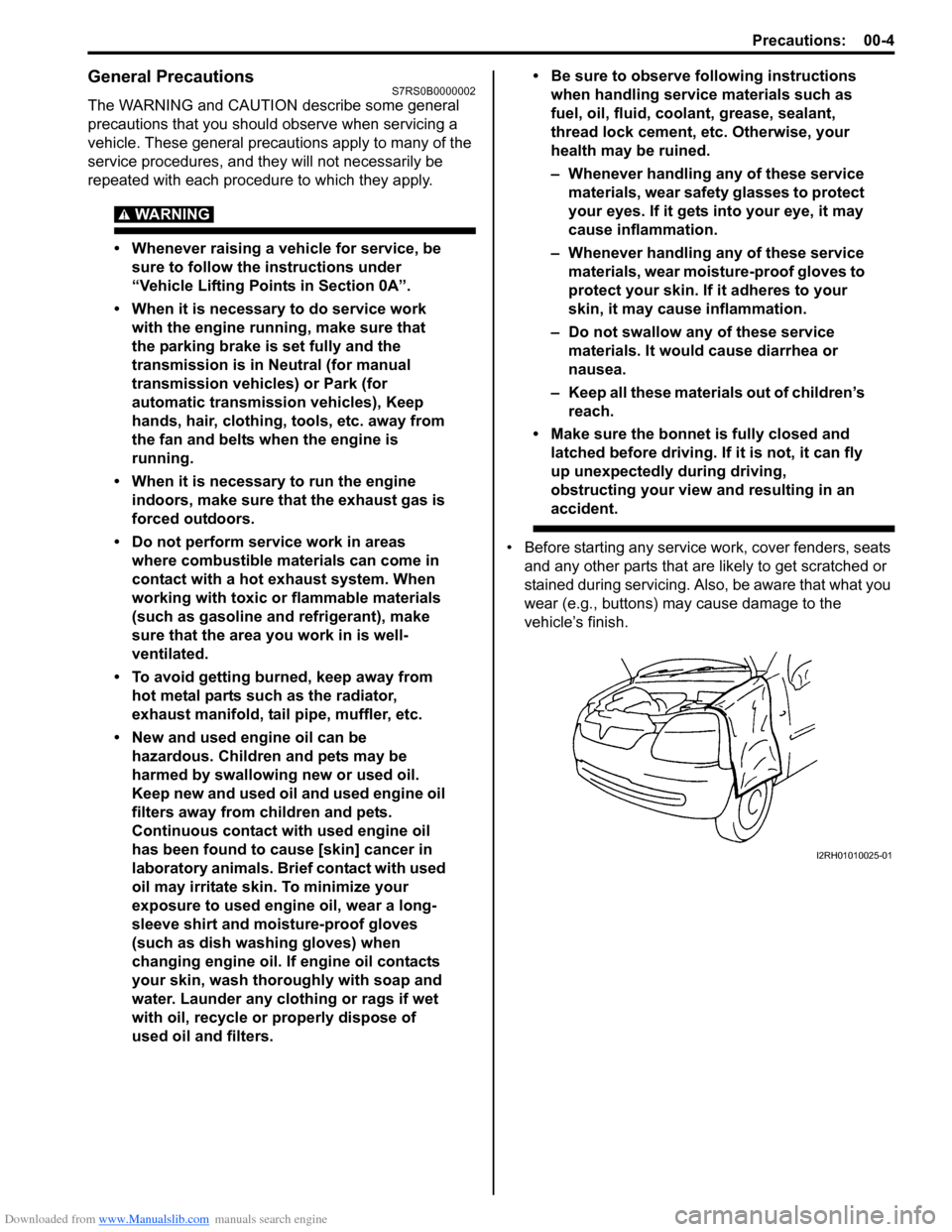
• Before starting any service work, cover fenders, seats and any other parts that are likely to get scratched or
stained during servicing. Also, be aware that what you
wear (e.g., buttons) ma y cause damage to the
vehicle’s finish.
I2RH01010025-01
Page 32 of 1496
Downloaded from www.Manualslib.com manuals search engine 0B-2 Maintenance and Lubrication:
NOTE
• “R”: Replace or change
• “I”: Inspect and correct, replace or lubricate if necessary
• For spark plugs, replace every 50,000 km if the local law requires.
• Periodic replacement of fuel filter is not necessary if it is not instructed in “Periodic Maintenance Schedule” section of the Owner’s manual. The scheduled maintenance varies depending on the
vehicle specification.
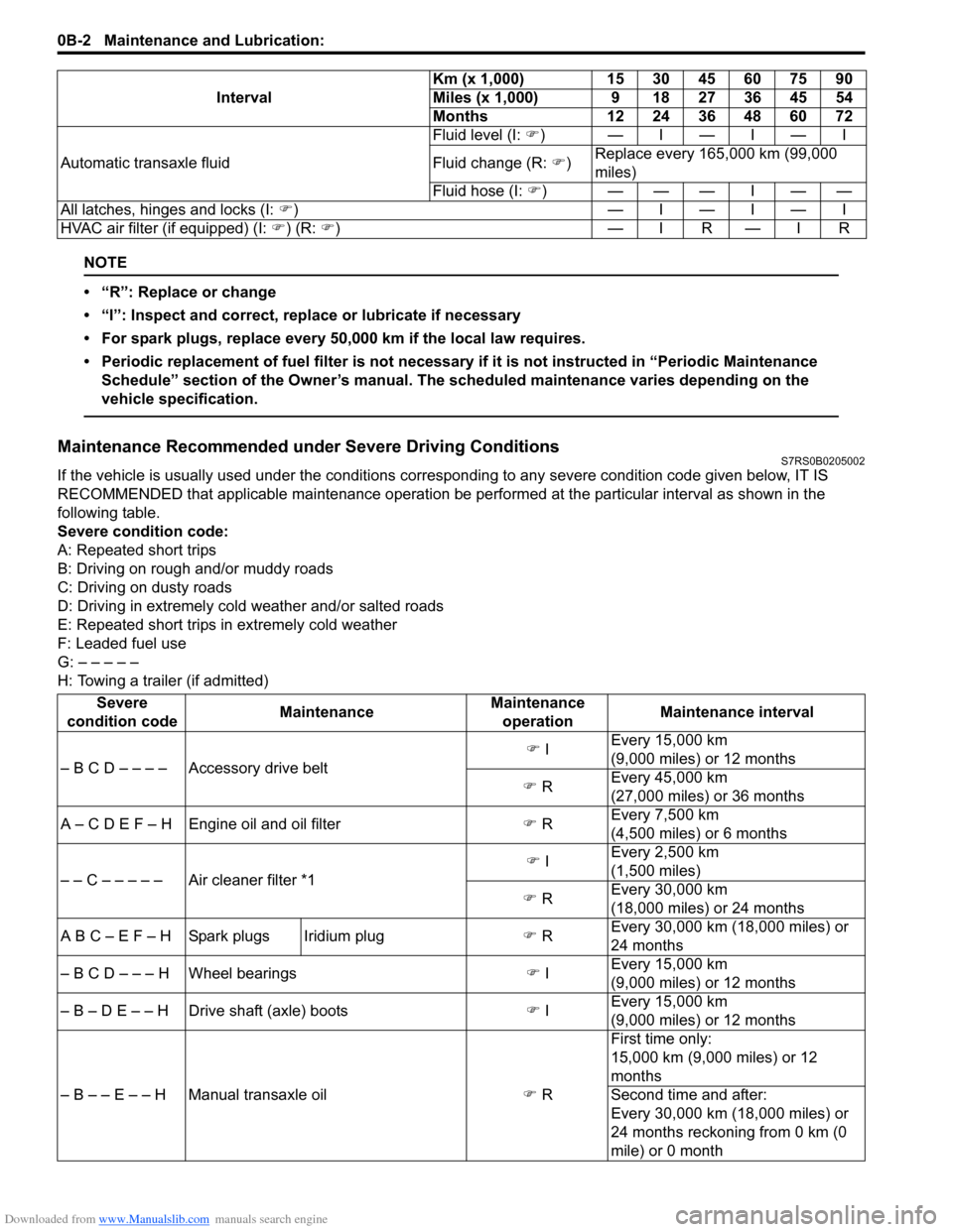
Maintenance Recommended under Severe Driving ConditionsS7RS0B0205002
If the vehicle is usually used under the conditions corres ponding to any severe condition code given below, IT IS
RECOMMENDED that applicable maintenance operation be per formed at the particular interval as shown in the
following table.
Severe condition code:
A: Repeated short trips
B: Driving on rough and/or muddy roads
C: Driving on dusty roads
D: Driving in extremely cold weather and/or salted roads
E: Repeated short trips in extremely cold weather
F: Leaded fuel use
G: – – – – –
H: Towing a trailer (if admitted) Automatic transaxle fluid
Fluid level (I:
�)) —I—I—I
Fluid change (R: �)) Replace every 165,000 km (99,000
miles)
Fluid hose (I: �))———I——
All latches, hinges and locks (I: �)) —I—I—I
HVAC air filter (if equipped) (I: �) ) (R: �))— IR — IR
Interval
Km (x 1,000)
15 30 45 60 75 90
Miles (x 1,000) 9 18 27 36 45 54
Months 12 24 36 48 60 72
Severe
condition code MaintenanceMaintenance
operation Maintenance interval
– B C D – – – – Accessory drive belt �)
I Every 15,000 km
(9,000 miles) or 12 months
�) R Every 45,000 km
(27,000 miles) or 36 months
A – C D E F – H Engine oil and oil filter �) R Every 7,500 km
(4,500 miles) or 6 months
– – C – – – – – Air cleaner filter *1 �)
I Every 2,500 km
(1,500 miles)
�) R Every 30,000 km
(18,000 miles) or 24 months
A B C – E F – H Spark plugs Iridium plug �) R Every 30,000 km (18,000 miles) or
24 months
– B C D – – – H Wheel bearings �) I Every 15,000 km
(9,000 miles) or 12 months
– B – D E – – H Drive shaft (axle) boots �) I Every 15,000 km
(9,000 miles) or 12 months
– B – – E – – H Manual transaxle oil �) R First time only:
15,000 km (9,000 miles) or 12
months
Second time and after:
Every 30,000 km (18,000 miles) or
24 months reckoning from 0 km (0
mile) or 0 month
Page 34 of 1496
Downloaded from www.Manualslib.com manuals search engine 0B-4 Maintenance and Lubrication:
Accessory Drive Belt ReplacementS7RS0B0206002
Water Pump and Generator Drive Belt
Replace belt with new one referring to “Water Pump /
Generator Drive Belt Removal and Installation in Section
1J”.
A/C Compressor Drive Belt
Replace belt with new one referring to “Compressor
Drive Belt Removal and Inst allation in Section 7B”.
Valve Lash (Clearance) InspectionS7RS0B0206003
Inspect intake and exhaust valve lash and adjust as
necessary.
Refer to “Valve Lash (Clearance) Inspection in Section
1D” for valve lash inspection and adjustment procedure.
Engine Oil and Filter ChangeS7RS0B0206004
WARNING!
• New and used engine oil can be
hazardous.
Be sure to read “WARNING” in “General
Precautions in Section 00” and observe
what is written there.
• Step 1) – 7) outlined below must be performed with ENGINE NOT RUNNING.
For Step 8), be sure to have adequate
ventilation while engine is running.
Before draining engine oil, check engine for oil leakage.
If any evidence of leakage is found, make sure to correct
defective part before proceeding to the following work.
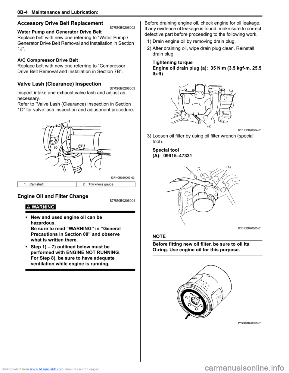
1) Drain engine oil by removing drain plug.
2) After draining oil, wipe drain plug clean. Reinstall drain plug.
Tightening torque
Engine oil drain plug (a): 35 N·m (3.5 kgf-m, 25.5
lb-ft)
3) Loosen oil filter by using oil filter wrench (special
tool).
Special tool
(A): 09915–47331
NOTE
Before fitting new oil filter, be sure to oil its
O-ring. Use engine oil for this purpose.
1. Camshaft 2. Thickness gauge
I2RH0B020003-02
I2RH0B020004-01
I2RH0B020005-01
IYSQ01020009-01
Page 36 of 1496
Downloaded from www.Manualslib.com manuals search engine 0B-6 Maintenance and Lubrication:
Exhaust System InspectionS7RS0B0206006
WARNING!
To avoid danger of being burned, do not
touch exhaust system when it is still hot.
Any service on exhaust system should be
performed when it is cool.
When carrying out periodic maintenance, or the vehicle
is raised for other service, check exhaust system as
follows:
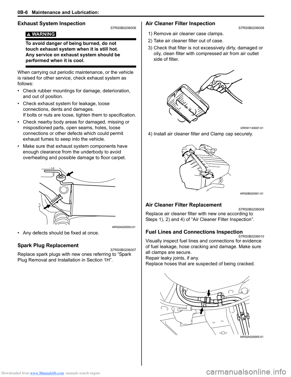
• Check rubber mountings for damage, deterioration, and out of position.
• Check exhaust system for leakage, loose connections, dents and damages.
If bolts or nuts are loose, tighten them to specification.
• Check nearby body areas for damaged, missing or mispositioned parts, ope n seams, holes, loose
connections or other defects which could permit
exhaust fumes to seep into the vehicle.
• Make sure that exhaust system components have enough clearance from the underbody to avoid
overheating and possible damage to floor carpet.
• Any defects should be fixed at once.
Spark Plug ReplacementS7RS0B0206007
Replace spark plugs with new ones referring to “Spark
Plug Removal and Installation in Section 1H”.
Air Cleaner Filter InspectionS7RS0B0206008
1) Remove air cleaner case clamps.
2) Take air cleaner filter out of case.
3) Check that filter is not excessively dirty, damaged or oily, clean filter with compressed air from air outlet
side of filter.
4) Install air cleaner filter and Clamp cap securely.
Air Cleaner Filter ReplacementS7RS0B0206009
Replace air cleaner filter with new one according to
Steps 1), 2) and 4) of “Air Cleaner Filter Inspection”.
Fuel Lines and Connections InspectionS7RS0B0206010
Visually inspect fuel lines and connections for evidence
of fuel leakage, hose cracking and damage. Make sure
all clamps are secure.
Repair leaky joints, if any.
Replace hoses that are suspected of being cracked.
I4RS0A020003-01
I2RH01140007-01
I4RS0B020001-01
I4RS0A020005-01
Page 43 of 1496
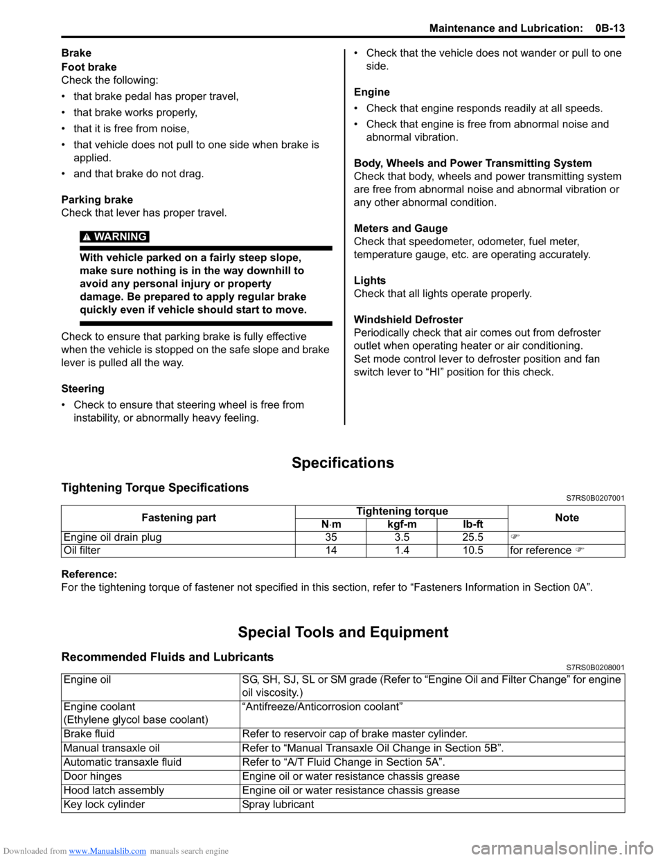
Downloaded from www.Manualslib.com manuals search engine Maintenance and Lubrication: 0B-13
Brake
Foot brake
Check the following:
• that brake pedal has proper travel,
• that brake works properly,
• that it is free from noise,
• that vehicle does not pull to one side when brake is applied.
• and that brake do not drag.
Parking brake
Check that lever has proper travel.
WARNING!
With vehicle parked on a fairly steep slope,
make sure nothing is in the way downhill to
avoid any personal injury or property
damage. Be prepared to apply regular brake
quickly even if vehicle should start to move.
Check to ensure that parking brake is fully effective
when the vehicle is stopped on the safe slope and brake
lever is pulled all the way.
Steering
• Check to ensure that steering wheel is free from instability, or abnormally heavy feeling. • Check that the vehicle does not wander or pull to one
side.
Engine
• Check that engine responds readily at all speeds.
• Check that engine is free from abnormal noise and abnormal vibration.
Body, Wheels and Power Transmitting System
Check that body, wheels and power transmitting system
are free from abnormal noise and abnormal vibration or
any other abnormal condition.
Meters and Gauge
Check that speedometer, odometer, fuel meter,
temperature gauge, etc. are operating accurately.
Lights
Check that all lights operate properly.
Windshield Defroster
Periodically check that ai r comes out from defroster
outlet when operating heater or air conditioning.
Set mode control lever to defroster position and fan
switch lever to “HI” position for this check.
Specifications
Tightening Torque SpecificationsS7RS0B0207001
Reference:
For the tightening torque of fastener not specified in this section, refer to “Fasteners Information in Section 0A”.
Special Tools and Equipment
Recommended Fluids and LubricantsS7RS0B0208001
Fastening part Tightening torque
Note
N ⋅mkgf-mlb-ft
Engine oil drain plug 35 3.5 25.5 �)
Oil filter 14 1.4 10.5 for reference �)
Engine oilSG, SH, SJ, SL or SM grade (Refer to “Engine Oil and Filter Change” for engine
oil viscosity.)
Engine coolant
(Ethylene glycol base coolant) “Antifreeze/Antico
rrosion coolant”
Brake fluid Refer to reservoir cap of brake master cylinder.
Manual transaxle oil Refer to “Manual Transaxle Oil Change in Section 5B”.
Automatic transaxle fluid Refer to “A/T Fluid Change in Section 5A”.
Door hinges Engine oil or water resistance chassis grease
Hood latch assembly Engine oil or water resistance chassis grease
Key lock cylinder Spray lubricant
Page 87 of 1496
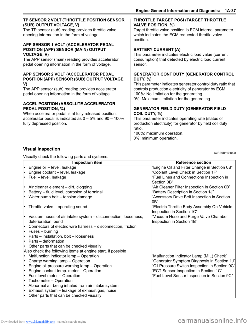
Downloaded from www.Manualslib.com manuals search engine Engine General Information and Diagnosis: 1A-37
TP SENSOR 2 VOLT (THROTTLE POSITION SENSOR
(SUB) OUTPUT VOLTAGE, V)
The TP sensor (sub) reading provides throttle valve
opening information in the form of voltage.
APP SENSOR 1 VOLT (ACCELERATOR PEDAL
POSITION (APP) SENSOR (MAIN) OUTPUT
VOLTAGE, V)
The APP sensor (main) read ing provides accelerator
pedal opening information in the form of voltage.
APP SENSOR 2 VOLT (ACCELERATOR PEDAL
POSITION (APP) SENSOR (S UB) OUTPUT VOLTAGE,
V)
The APP sensor (sub) reading provides accelerator
pedal opening information in the form of voltage.
ACCEL POSITION (ABSOLUTE ACCELERATOR
PEDAL POSITION, %)
When accelerator pedal is at fully released position,
accelerator pedal is indicated as 0 – 5% and 90 – 100%
fully depressed position. THROTTLE TARGET POSI (TARGET THROTTLE
VALVE POSITION, %)
Target throttle valve position is ECM internal parameter
which indicates the ECM requested throttle valve
position.
BATTERY CURRENT (A)
This parameter indicates elec
tric load value (current
consumption) that detected by electric load current
sensor.
GENERATOR CONT DUTY (GENERATOR CONTROL
DUTY, %)
This parameter indicates generator control duty ratio that
controls production electricity of generator by ECM.
100%: No limitation for the generating
0%: Maximum limitation for the generating
GENERATOR FIELD DUTY (GENERATOR FIELD
COIL DUTY, %)
This parameter indicates ope rating rate (status of
production electricity) for gen erator by field coil duty
ratio.
100%: maximum operation.
0%: minimum operation.
Visual InspectionS7RS0B1104008
Visually check the following parts and systems.
Inspection item Reference section
• Engine oil – level, leakage “Engine Oil and Filter Change in Section 0B”
• Engine coolant – level, leakage “Co olant Level Check in Section 1F”
• Fuel – level, leakage “Fuel Lines and Connections Inspection in Section 0B”
• Air cleaner element – dirt, clogging “Air Cleaner Filter Inspection in Section 0B”
• Battery – fluid level, corrosion of terminal “Battery Description in Section 1J”
• Water pump belt – tension damage “Accessory Drive Belt Inspection in Section 0B”
• Throttle valve – operating sound “Electric Throttle Body Assembly On-Vehicle Inspection in Section 1C”
• Vacuum hoses of air intake system – disconnection, looseness,
deterioration, bend “Vacuum Hose and Purge Valve Chamber
Inspection in Section 1B”
• Connectors of electric wire harness – disconnection, friction
• Fuses – burning
• Parts – installation, bolt – looseness
• Parts – deformation
• Other parts that can be checked visually
Also check the following items at engine start, if possible
• Malfunction indicator lamp – Operation “Malfunction Indicator Lamp (MIL) Check”
• Charge warning lamp – Operation “Genera tor Symptom Diagnosis in Section 1J”
• Engine oil pressure warning lamp – Operation “O il Pressure Switch Inspection in Section 9C”
• Engine coolant temp. meter – Operation “ECT Sensor Inspection in Section 1C”
• Fuel level meter – Operation “Fuel Level Sensor Inspection in Section 9C”
• Tachometer – Operation
• Abnormal air being inhaled from air intake system
• Exhaust system – leakage of exhaust gas, noise
• Other parts that can be checked visually
Page 91 of 1496

Downloaded from www.Manualslib.com manuals search engine Engine General Information and Diagnosis: 1A-41
Engine Symptom DiagnosisS7RS0B1104010
Perform troubleshooting referring to the followings when ECM has detected no DTC and no abnormality has been
found in “Visual Inspection” and “Engine Basic Inspection”.
Condition Possible cause Correction / Reference Item
Hard starting (Engine
cranks OK) Faulty spark plug
“Spark Plug Inspection in Section 1H”
Leaky high-tension cord “High-Tension Cord Inspection in Section 1H”
Loose connection or disconnection of
high-tension cord(s) or lead wire(s) “High-Tension Cord Removal and Installation
in Section 1H”
Faulty ignition coil “Ignition Coil Assembly (Including ignitor)
Inspection in Section 1H”
Dirty or clogged fuel hose or pipe “Fuel Pressure Check”
Malfunctioning fuel pump “Fuel Pressure Check”
Air drawn in through intake manifold
gasket or throttle body gasket
Faulty electric throttle body assembly “Electric Throttle Body Assembly On-Vehicle
Inspection in Section 1C”
Faulty APP sensor assembly “APP Sensor Assembly Inspection in Section
1C”
Faulty ECT sensor or MAF sensor “ECT Sensor Inspection in Section 1C” or
“MAF and IAT Sensor Inspection in Section
1C”
Faulty ECM
Low compression “Compression Check in Section 1D”
Poor spark plug tightening or faulty
gasket “Spark Plug Removal and Installation in
Section 1H”
Compression leak from valve seat “Valves and Valve Guides Inspection in
Section 1D”
Sticky valve stem “Valves and Valve Guides Inspection in
Section 1D”
Weak or damaged valve springs “Valve Spring Inspection in Section 1D”
Compression leak at cylinder head
gasket “Cylinder Head Inspection in Section 1D”
Sticking or damaged piston ring “Cylinders, Pistons and Piston Rings
Inspection in Section 1D”
Worn piston, ring or cylinder “Cylinders, Pistons and Piston Rings
Inspection in Section 1D”
Malfunctioning PCV valve “PCV Valve Inspection in Section 1B”
Camshaft position control (VVT) system
out of order “Oil Control Valve Inspection in Section 1D”
Faulty EGR system “EGR System Inspection in Section 1B”
Low oil pressure Improper oil viscosity “Engine Oil and Filter Change in Section 0B”
Malfunctioning oil pressure switch “Oil Pressure Switch Inspection in Section 9C”
Clogged oil strainer “Oil Pan and Oil Pump Strainer Cleaning in
Section 1E”
Functional deterioration of oil pump “Oil Pump Inspection in Section 1E”
Worn oil pump relief valve “Oil Pump Inspection in Section 1E”
Excessive clearance in various sliding
parts
Engine noise – Valve
noise
NOTE
Before checking
mechanical noise, make
sure that:
• Specified spark plug is used.
• Specified fuel is used.
Improper valve lash “Camshaft, Tappet and Shim Inspection in
Section 1D”
Worn valve stem and guide “Valves and Valve Guides Inspection in
Section 1D”
Weak or broken valve spring “Valve Spring Inspection in Section 1D”
Warped or bent valve “Valves and Valve Guides Inspection in
Section 1D”
Page 305 of 1496

Downloaded from www.Manualslib.com manuals search engine Engine Mechanical: 1D-20
15) Install A/C compressor to its bracket (if equipped) referring to “Compressor Assembly Removal and
Installation in Section 7B” or “Compressor Assembly
Removal and Installa tion in Section 7B”.
16) Adjust A/C compressor belt tension (if equipped) referring to “Compressor Drive Belt Inspection and
Adjustment in Section 7B” or “Compressor Drive Belt
Inspection and Adjustment in Section 7B”.
17) Check to ensure that a ll removed parts are back in
place.
Reinstall any necessary parts which have not been
reinstalled.
18) Refill cooling system with coolant referring to “Cooling System Flush and Refill in Section 1F”. 19) Refill engine with engine oil
referring to “Engine Oil
and Filter Change in Section 0B”.
20) Refill transaxle with transa xle oil referring to“Manual
Transaxle Oil Change in Section 5B” or “A/T Fluid
Change in Section 5A”.
21) Install battery and tray.
22) Connect positive and negative cable at battery.
23) Install engine hood and connect windshield washer hose.
24) Verify that there is no fu el leakage, coolant leakage,
oil leakage and exhaust gas leakage at each
connection.
Timing Chain Cover ComponentsS7RS0B1406012
I6RS0C140015-02
1. Crankshaft pulley bolt 13. Oil gallery pipe No.2 bolt
2. Crankshaft pulley 14. Oil gallery pipe No.3
3. Oil seal : Apply engine oil to oil seal lip. 15. Oil gallery pipe No.3 bolt
4. Timing chain cover : Apply sealant 99000-31140 to the mating surface of cylinder and cylinder head.
: Apply sealant 99000-31260 to the mating surface of timing chain cover referring to the
figure of Step 4) of “Installation” under “Timing Chain Cover Removal and Installation”. 16. O-ring
: Apply engine oil.
5. Pin 17. Oil control valve
6. Cap bolt 18. Oil control valve mounting nut
7. Timing chain cover mounting bolts 19. Cap
8. Timing chain cover mounting nut : 11 N ⋅m (1.1 kgf-m, 8.0 lb-ft)
9. Oil gallery pipe No.1 :25 N⋅m (2.5 kgf-m, 18.0 lb-ft)