2006 SUZUKI SWIFT Lever
[x] Cancel search: LeverPage 1021 of 1496
Downloaded from www.Manualslib.com manuals search engine Air Conditioning System: Automatic Type 7B-73
HVAC Unit Removal and InstallationS7RS0B7226003
Refer to “HVAC Unit Removal and Installation”.
Temperature Control Actuator Removal and
Installation
S7RS0B7226004
Removal1) Disconnect negative (–) cable at battery.
2) Remove steering column hol e cover from instrument
panel.
3) Remove foot duct from HVAC unit.
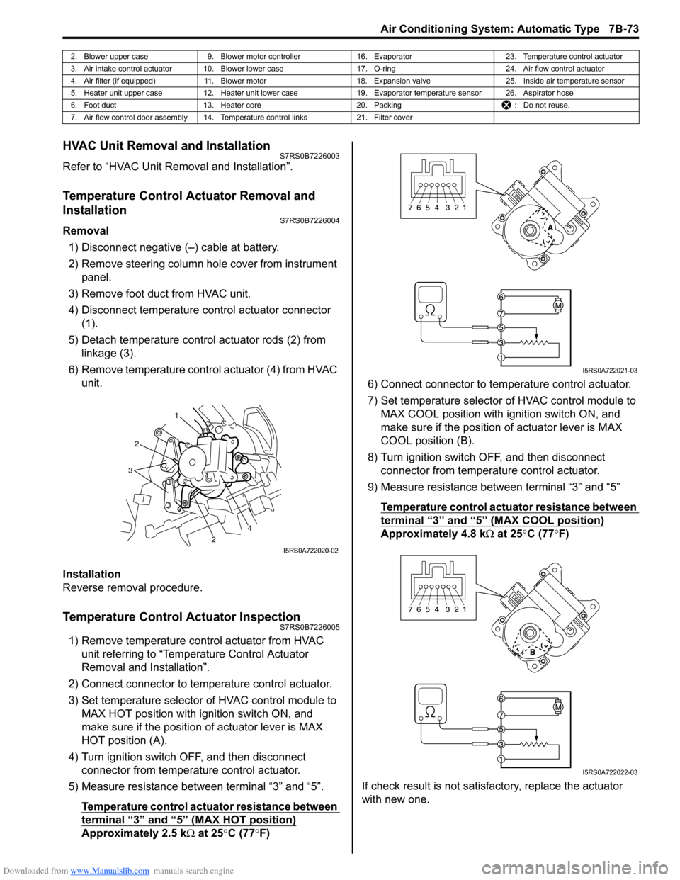
4) Disconnect temperature control actuator connector (1).
5) Detach temperature control actuator rods (2) from linkage (3).
6) Remove temperature control actuator (4) from HVAC unit.
Installation
Reverse removal procedure.
Temperature Control Actuator InspectionS7RS0B7226005
1) Remove temperature control actuator from HVAC unit referring to “Temperature Control Actuator
Removal and Installation”.
2) Connect connector to temperature control actuator.
3) Set temperature selector of HVAC control module to MAX HOT position with ignition switch ON, and
make sure if the position of actuator lever is MAX
HOT position (A).
4) Turn ignition switch OFF, and then disconnect connector from temperature control actuator.
5) Measure resistance between terminal “3” and “5”.
Temperature control actuator resistance between
terminal “3” and “5” (MAX HOT position)
Approximately 2.5 k Ω at 25 °C (77 °F) 6) Connect connector to tem
perature control actuator.
7) Set temperature selector of HVAC control module to MAX COOL position with ignition switch ON, and
make sure if the position of actuator lever is MAX
COOL position (B).
8) Turn ignition switch OFF, and then disconnect connector from temperature control actuator.
9) Measure resistance between terminal “3” and “5”
Temperature control actuator resistance between
terminal “3” and “5” (MAX COOL position)
Approximately 4.8 k Ω at 25 °C (77 °F)
If check result is not satisfactory, replace the actuator
with new one.
2. Blower upper case 9. Blower motor controller 16. Evaporator 23. Temperature control actuator
3. Air intake control actuator 10. Blower lower case 17. O-ring24. Air flow control actuator
4. Air filter (if equipped) 11. Blower motor 18. Expansion valve25. Inside air temperature sensor
5. Heater unit upper case 12. Heater unit lower case 19. Evaporator temperature sensor 26. Aspirator hose
6. Foot duct 13. Heater core 20. Packing : Do not reuse.
7. Air flow control door assembly 14. Temperature control links 21. Filter cover
1
2
2
3
4
I5RS0A722020-02
I5RS0A722021-03
I5RS0A722022-03
Page 1022 of 1496
Downloaded from www.Manualslib.com manuals search engine 7B-74 Air Conditioning System: Automatic Type
Air Flow Control Actuator Removal and
Installation
S7RS0B7226006
Removal1) Disconnect negative (–) cable at battery.
2) Remove steering column hol e cover from instrument
panel.
3) Remove foot duct from HVAC unit.
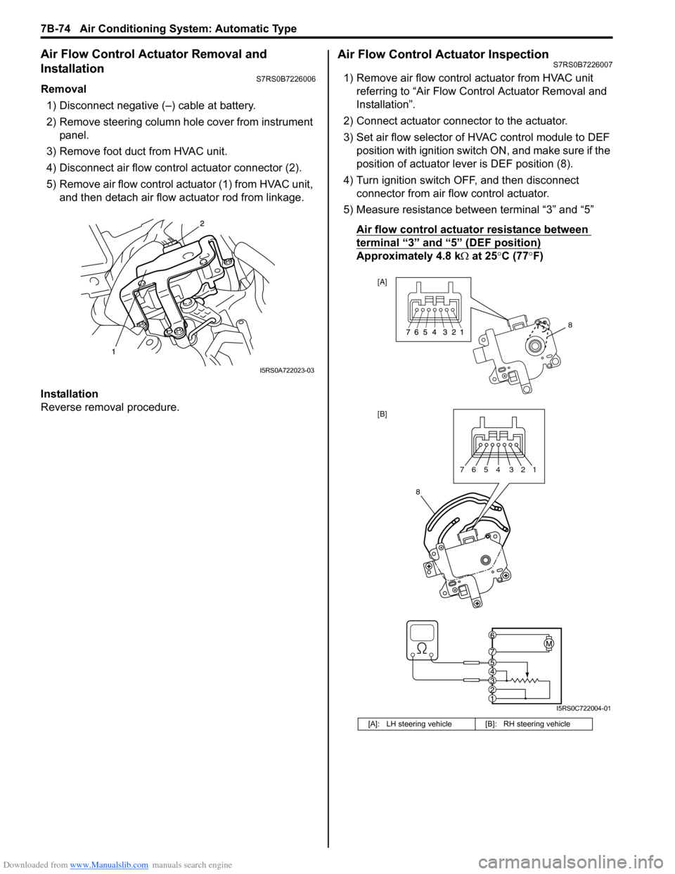
4) Disconnect air flow contro l actuator connector (2).
5) Remove air flow control actuator (1) from HVAC unit, and then detach air flow actuator rod from linkage.
Installation
Reverse removal procedure.
Air Flow Control Actuator InspectionS7RS0B7226007
1) Remove air flow control actuator from HVAC unit referring to “Air Flow C ontrol Actuator Removal and
Installation”.
2) Connect actuator connector to the actuator.
3) Set air flow selector of HVAC control module to DEF position with ignition switch ON, and make sure if the
position of actuator lever is DEF position (8).
4) Turn ignition switch OFF, and then disconnect connector from air flow control actuator.
5) Measure resistance between terminal “3” and “5”
Air flow control actuator resistance between
terminal “3” and “5” (DEF position)
Approximately 4.8 k Ω at 25 °C (77 °F)
I5RS0A722023-03
[A]: LH steering vehicle [B]: RH steering vehicle
8
[A]
[B]
8
7654 321
I5RS0C722004-01
Page 1023 of 1496
Downloaded from www.Manualslib.com manuals search engine Air Conditioning System: Automatic Type 7B-75
6) Connect connector to air flow control actuator.
7) Set air flow selector of HVAC control module to VENT position with ignition switch ON, and make
sure if the position of act uator lever is VENT position
(8).
8) Turn ignition switch OFF, and then disconnect connector from air flow control actuator.
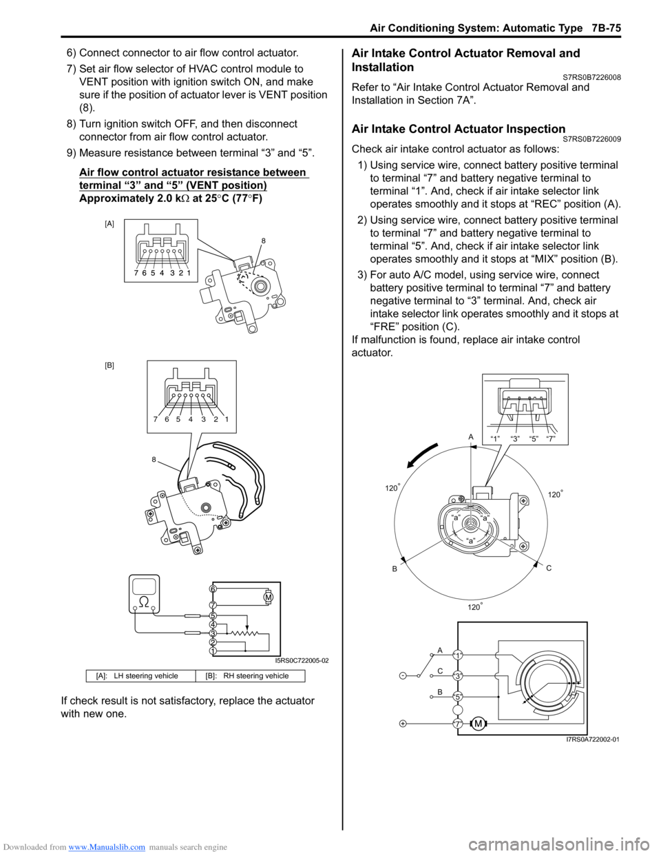
9) Measure resistance between terminal “3” and “5”.
Air flow control actuator resistance between
terminal “3” and “5” (VENT position)
Approximately 2.0 k Ω at 25 °C (77 °F)
If check result is not satisfactory, replace the actuator
with new one.
Air Intake Control Actuator Removal and
Installation
S7RS0B7226008
Refer to “Air Intake Control Actuator Removal and
Installation in Section 7A”.
Air Intake Control Actuator InspectionS7RS0B7226009
Check air intake contro l actuator as follows:
1) Using service wire, connect battery positive terminal
to terminal “7” and battery negative terminal to
terminal “1”. And, check if air intake selector link
operates smoothly and it stops at “REC” position (A).
2) Using service wire, connect battery positive terminal
to terminal “7” and battery negative terminal to
terminal “5”. And, check if air intake selector link
operates smoothly and it stops at “MIX” position (B).
3) For auto A/C model, using service wire, connect battery positive terminal to terminal “7” and battery
negative terminal to “3” terminal. And, check air
intake selector link operates smoothly and it stops at
“FRE” position (C).
If malfunction is found, replace air intake control
actuator.
[A]: LH steering vehicl e [B]: RH steering vehicle
[A]
[B]
8
8765 4 3 21
I5RS0C722005-02
A
C
B“a”
“a”“a”
-
+
A
C
B “1” “3” “5” “7”
“1”
“3”
“5”
“7”
120
°
120° 120
°
I7RS0A722002-01
Page 1157 of 1496
Downloaded from www.Manualslib.com manuals search engine Air Bag System: 8B-119
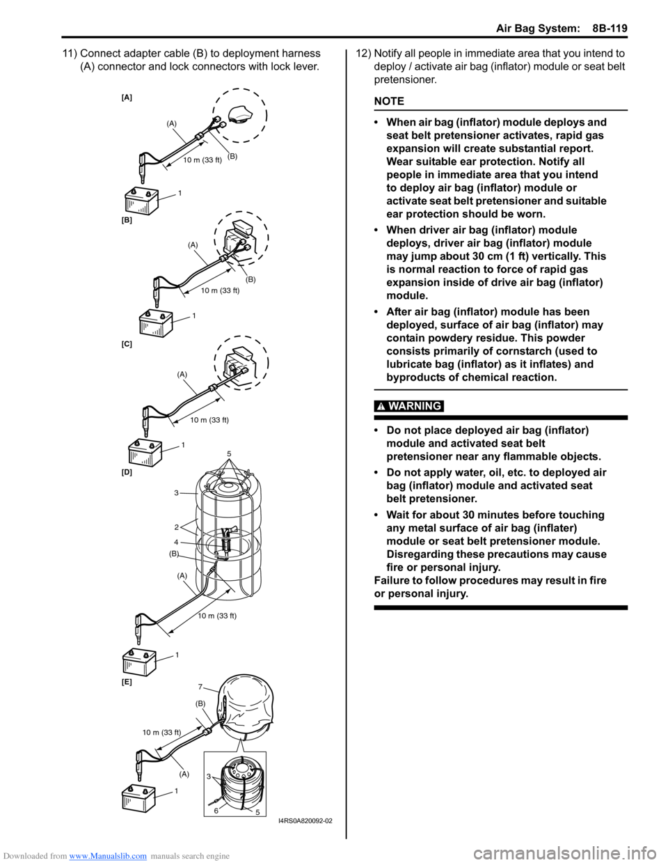
11) Connect adapter cable (B) to deployment harness (A) connector and lock connectors with lock lever. 12) Notify all people in immediate area that you intend to
deploy / activate air bag (inflator) module or seat belt
pretensioner.
NOTE
• When air bag (inflator) module deploys and seat belt pretensioner activates, rapid gas
expansion will create substantial report.
Wear suitable ear protection. Notify all
people in immediate area that you intend
to deploy air bag (inflator) module or
activate seat belt pretensioner and suitable
ear protection should be worn.
• When driver air bag (inflator) module deploys, driver air bag (inflator) module
may jump about 30 cm (1 ft) vertically. This
is normal reaction to force of rapid gas
expansion inside of drive air bag (inflator)
module.
• After air bag (inflator) module has been deployed, surface of air bag (inflator) may
contain powdery residue. This powder
consists primarily of cornstarch (used to
lubricate bag (inflator) as it inflates) and
byproducts of chemical reaction.
WARNING!
• Do not place deployed air bag (inflator) module and activated seat belt
pretensioner near any flammable objects.
• Do not apply water, oil, etc. to deployed air bag (inflator) module and activated seat
belt pretensioner.
• Wait for about 30 minutes before touching any metal surface of air bag (inflater)
module or seat belt pretensioner module.
Disregarding these precautions may cause
fire or personal injury.
Failure to follow procedures may result in fire
or personal injury.
[A]
10 m (33 ft)
(A)
(B)
1
10 m (33 ft)
(A)
(B) 1
5
3 2
4
(A)
[B]
[C]
[D]
[E]
7
3
6 5
(A) (B)
1
10 m (33 ft)
10 m (33 ft)
(A)
(B)
1
1
10 m (33 ft)
I4RS0A820092-02
Page 1195 of 1496
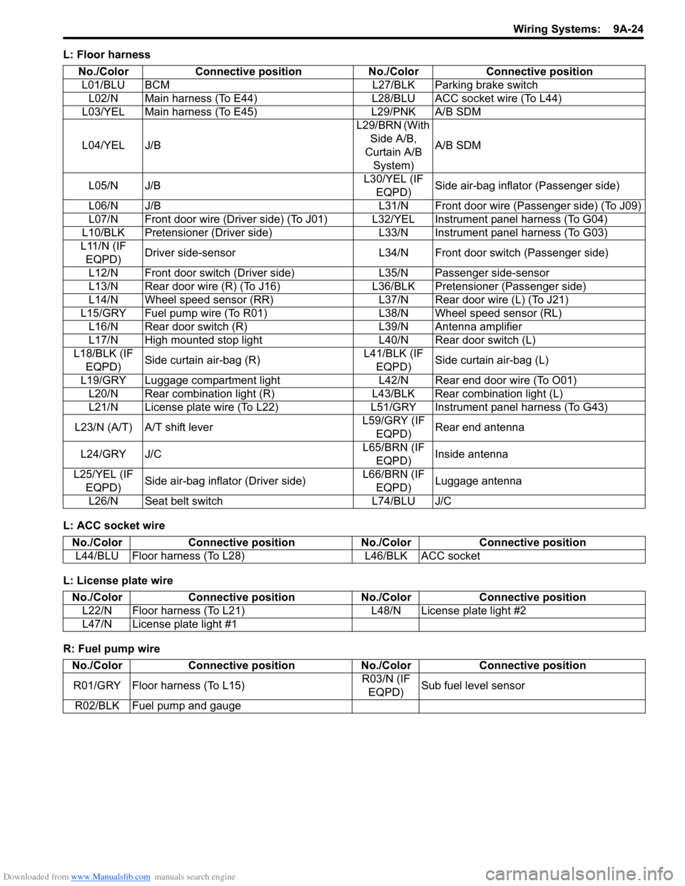
Downloaded from www.Manualslib.com manuals search engine Wiring Systems: 9A-24
L: Floor harness
L: ACC socket wire
L: License plate wire
R: Fuel pump wireNo./Color Connective position No./Color Connective position
L01/BLU BCM L27/BLK Parking brake switch L02/N Main harness (To E44) L28/BLU ACC socket wire (To L44)
L03/YEL Main harness (To E45) L29/PNK A/B SDM
L04/YEL J/B L29/BRN (With
Side A/B,
Curtain A/B System) A/B SDM
L05/N J/B L30/YEL (IF
EQPD) Side air-bag inflator (Passenger side)
L06/N J/B L31/N Front door wire (Passenger side) (To J09)
L07/N Front door wire (Driver side) (To J01) L32/YEL Instrument panel harness (To G04)
L10/BLK Pretensioner (Driver side) L33/N Instrument panel harness (To G03)
L11/N (IF EQPD) Driver side-sensor L34/N Front door switch (Passenger side)
L12/N Front door switch (Driver side) L35/N Passenger side-sensor
L13/N Rear door wire (R) (To J16) L 36/BLK Pretensioner (Passenger side)
L14/N Wheel speed sensor (RR) L37/N Rear door wire (L) (To J21)
L15/GRY Fuel pump wire (To R01) L38/N Wheel speed sensor (RL)
L16/N Rear door switch (R) L39/N Antenna amplifier
L17/N High mounted stop light L40/N Rear door switch (L)
L18/BLK (IF EQPD) Side curtain air-bag (R) L41/BLK (IF
EQPD) Side curtain air-bag (L)
L19/GRY Luggage compartment light L42/N Rear end door wire (To O01) L20/N Rear combination light (R) L43/BLK Rear combination light (L)
L21/N License plate wire (To L22) L51/ GRY Instrument panel harness (To G43)
L23/N (A/T) A/T shift lever L59/GRY (IF
EQPD) Rear end antenna
L24/GRY J/C L65/BRN (IF
EQPD) Inside antenna
L25/YEL (IF EQPD) Side air-bag inflator (Driver side) L66/BRN (IF
EQPD) Luggage antenna
L26/N Seat belt switch L74/BLU J/C
No./Color Connective position No./Color Connective position
L44/BLU Floor harness (To L28) L46/BLK ACC socket
No./ColorConnective position No./Color Connective position
L22/N Floor harness (To L21) L48/N License plate light #2
L47/N License plate light #1
No./Color Connective position No./Color Connective position
R01/GRY Floor harness (To L15) R03/N (IF
EQPD) Sub fuel level sensor
R02/BLK Fuel pump and gauge
Page 1197 of 1496
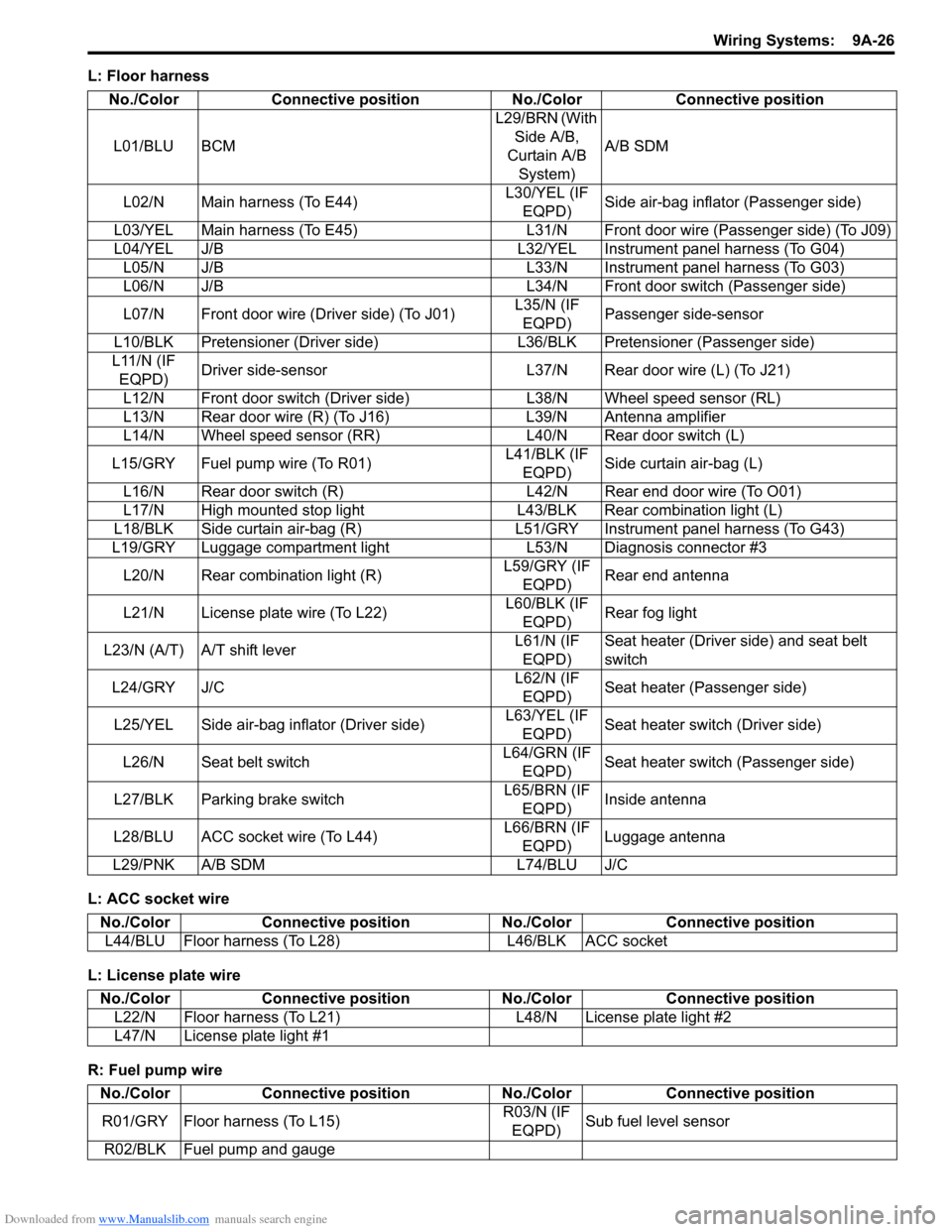
Downloaded from www.Manualslib.com manuals search engine Wiring Systems: 9A-26
L: Floor harness
L: ACC socket wire
L: License plate wire
R: Fuel pump wireNo./Color Connective position No./Color Connective position
L01/BLU BCM L29/BRN (With
Side A/B,
Curtain A/B System) A/B SDM
L02/N Main harness (To E44) L30/YEL (IF
EQPD) Side air-bag inflator (Passenger side)
L03/YEL Main harness (To E45) L31/N Front door wire (Passenger side) (To J09)
L04/YEL J/B L32/YEL Instrument panel harness (To G04) L05/N J/B L33/N Instrument panel harness (To G03)
L06/N J/B L34/N Front door switch (Passenger side)
L07/N Front door wire (Driver side) (To J01) L35/N (IF
EQPD) Passenger side-sensor
L10/BLK Pretensioner (Driver side) L36/ BLK Pretensioner (Passenger side)
L11/N (IF EQPD) Driver side-sensor L37/N Rear door wire (L) (To J21)
L12/N Front door switch (Driver side) L38/N Wheel speed sensor (RL)
L13/N Rear door wire (R) (To J16) L39/N Antenna amplifier
L14/N Wheel speed sensor (RR) L40/N Rear door switch (L)
L15/GRY Fuel pump wire (To R01) L41/BLK (IF
EQPD) Side curtain air-bag (L)
L16/N Rear door switch (R) L42/N Rear end door wire (To O01)
L17/N High mounted stop light L43/BLK Rear combination light (L)
L18/BLK Side curtain air-bag (R) L51/GRY Instrument panel harness (To G43)
L19/GRY Luggage compartment light L53/N Diagnosis connector #3
L20/N Rear combin ation light (R) L59/GRY (IF
EQPD) Rear end antenna
L21/N License plate wire (To L22) L60/BLK (IF
EQPD) Rear fog light
L23/N (A/T) A/T shift lever L61/N (IF
EQPD) Seat heater (Driver side) and seat belt
switch
L24/GRY J/C L62/N (IF
EQPD) Seat heater (Passenger side)
L25/YEL Side air-bag inflator (Driver side) L63/YEL (IF
EQPD) Seat heater switch (Driver side)
L26/N Seat belt switch L64/GRN (IF
EQPD) Seat heater switch (Passenger side)
L27/BLK Parking brake switch L65/BRN (IF
EQPD) Inside antenna
L28/BLU ACC socket wire (To L44) L66/BRN (IF
EQPD) Luggage antenna
L29/PNK A/B SDM L74/BLU J/C
No./Color Connective position No./Color Connective position
L44/BLU Floor harness (To L28) L46/BLK ACC socket
No./ColorConnective position No./Color Connective position
L22/N Floor harness (To L21) L48/N License plate light #2
L47/N License plate light #1
No./Color Connective position No./Color Connective position
R01/GRY Floor harness (To L15) R03/N (IF
EQPD) Sub fuel level sensor
R02/BLK Fuel pump and gauge
Page 1199 of 1496
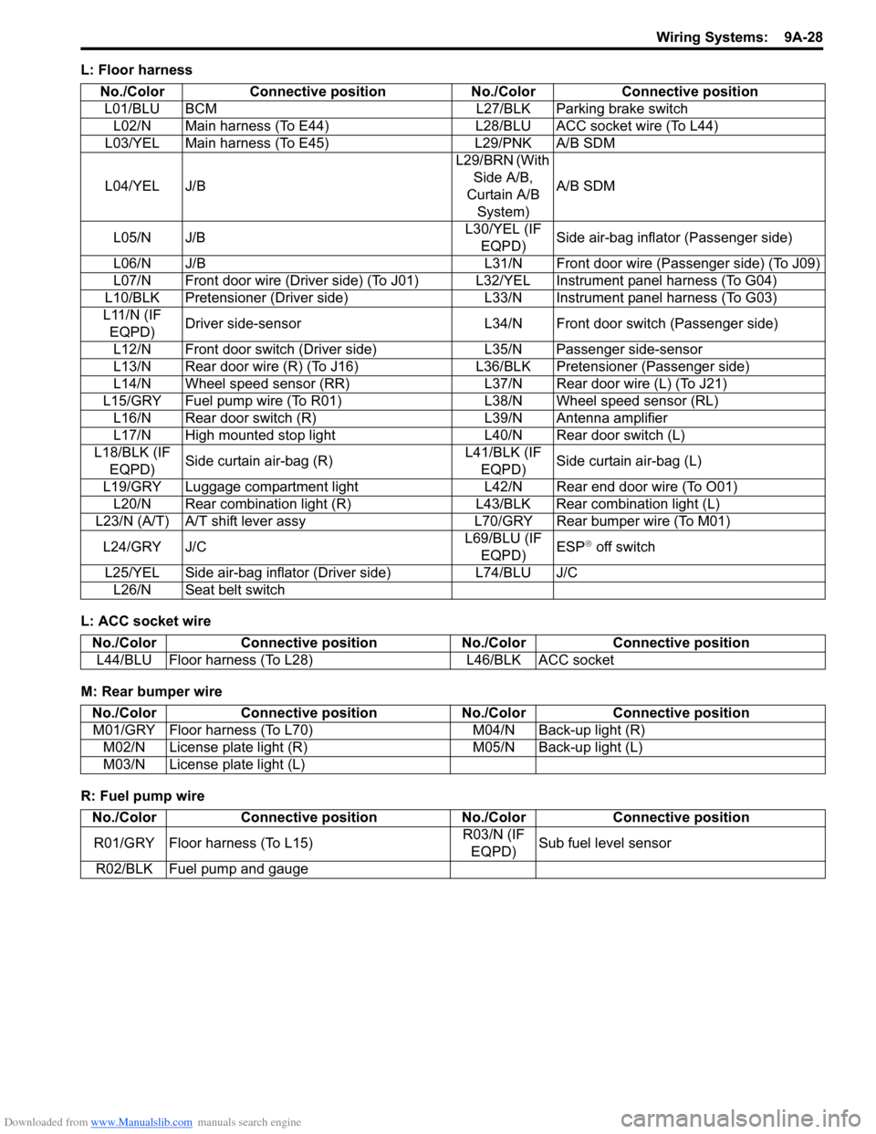
Downloaded from www.Manualslib.com manuals search engine Wiring Systems: 9A-28
L: Floor harness
L: ACC socket wire
M: Rear bumper wire
R: Fuel pump wireNo./Color Connective position No./Color Connective position
L01/BLU BCM L27/BLK Parking brake switch L02/N Main harness (To E44) L28/BLU ACC socket wire (To L44)
L03/YEL Main harness (To E45) L29/PNK A/B SDM
L04/YEL J/B L29/BRN (With
Side A/B,
Curtain A/B System) A/B SDM
L05/N J/B L30/YEL (IF
EQPD) Side air-bag inflator (Passenger side)
L06/N J/B L31/N Front door wire (Passenger side) (To J09)
L07/N Front door wire (Driver side) (To J01) L32/YEL Instrument panel harness (To G04)
L10/BLK Pretensioner (Driver side) L33/N Instrument panel harness (To G03)
L11/N (IF EQPD) Driver side-sensor L34/N Front door switch (Passenger side)
L12/N Front door switch (Driver side) L35/N Passenger side-sensor
L13/N Rear door wire (R) (To J16) L 36/BLK Pretensioner (Passenger side)
L14/N Wheel speed sensor (RR) L37/N Rear door wire (L) (To J21)
L15/GRY Fuel pump wire (To R01) L38/N Wheel speed sensor (RL)
L16/N Rear door switch (R) L39/N Antenna amplifier
L17/N High mounted stop light L40/N Rear door switch (L)
L18/BLK (IF EQPD) Side curtain air-bag (R) L41/BLK (IF
EQPD) Side curtain air-bag (L)
L19/GRY Luggage compartment light L42/N Rear end door wire (To O01) L20/N Rear combination light (R) L43/BLK Rear combination light (L)
L23/N (A/T) A/T shift lever assy L70/GRY Rear bumper wire (To M01)
L24/GRY J/C L69/BLU (IF
EQPD) ESP
® off switch
L25/YEL Side air-bag inflator (Driver side) L74/BLU J/C L26/N Seat belt switch
No./Color Connective position No./Color Connective position
L44/BLU Floor harness (To L28) L46/BLK ACC socket
No./ColorConnective position No./Color Connective position
M01/GRY Floor harness (To L70) M04/N Back-up light (R)
M02/N License plate light (R) M05/N Back-up light (L)
M03/N License plate light (L)
No./Color Connective position No./Color Connective position
R01/GRY Floor harness (To L15) R03/N (IF
EQPD) Sub fuel level sensor
R02/BLK Fuel pump and gauge
Page 1210 of 1496
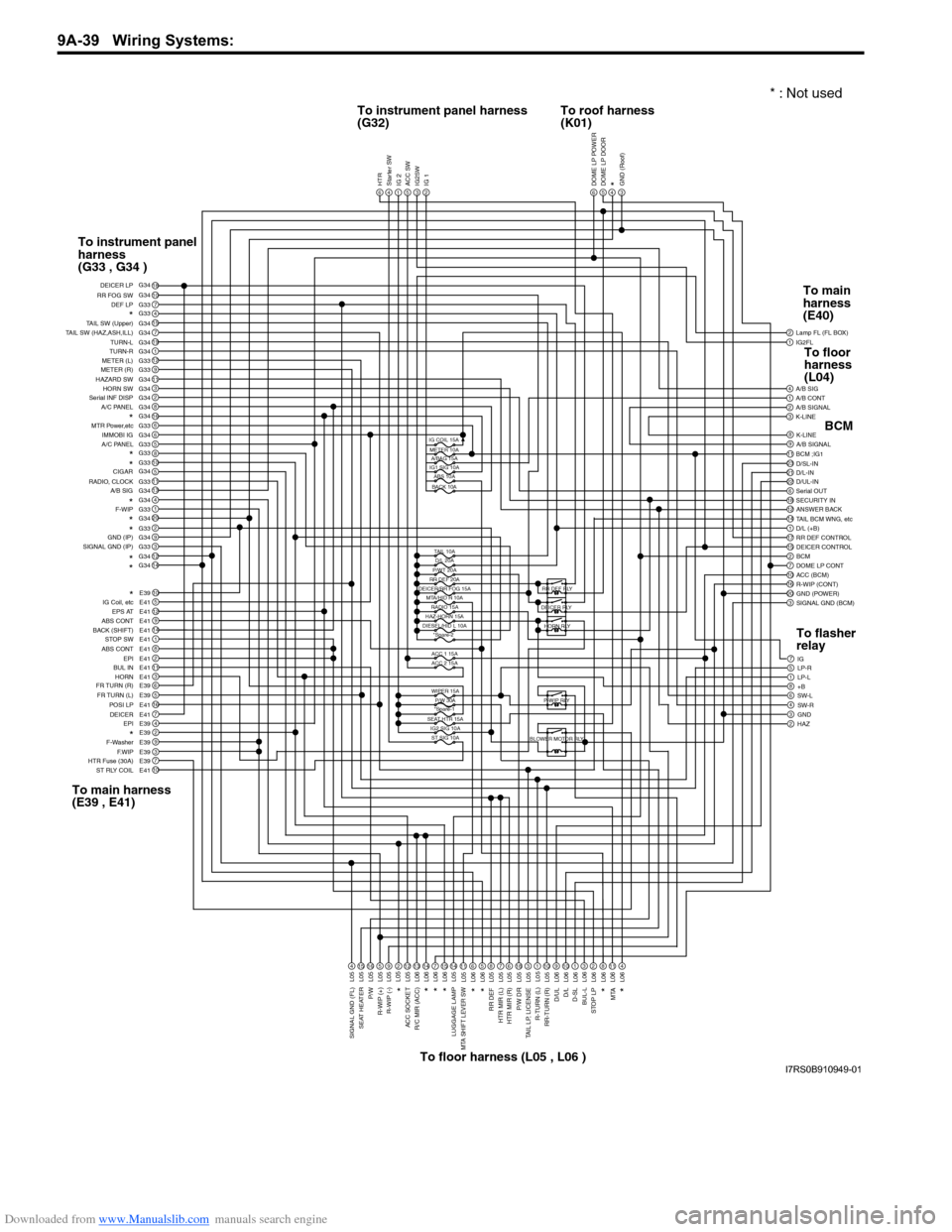
Downloaded from www.Manualslib.com manuals search engine 9A-39 Wiring Systems:
1IG2FL2
6
Lamp FL (FL BOX)
1A/B CONT4A/B SIG
3K-LINE2A/B SIGNAL
9A/B SIGNAL8K-LINE
2311BCM ;IG1
22D/UL-IN21D/L-IN D/SL-IN
18SECURITY IN6Serial OUT
14TAIL BCM WNG, etc12ANSWER BACK
17RR DEF CONTROL1D/L (+B)
2BCM15DEICER CONTROL
10ACC (BCM)7DOME LP CONT
20GND (POWER)16R-WIP (CONT)
3SIGNAL GND (BCM)
7IG
1LP-L5LP-R
8+B6SW-L
3GND4SW-R
2HAZ
DOME LP POWER5DOME LP DOOR4*3GND (Roof)6HTR4Starter SW1IG 25ACC SW3IG2SW2IG 1
18107G33415G347G3419G341G3412G339G3311G343G342G348G34166G336G345G33810511G3313G344G341G3320G342G339G343G3312G3414G34
10E395E4112E419E4114E411E418E412E4111E413E416E395E3916E417E414E392E399E393E397E3910E41
DEF LP
RR FOG SW DEICER LP
*TAIL SW (Upper)
TAIL SW (HAZ,ASH,ILL) TURN-L
TURN-R
METER (L)
METER (R)
HAZARD SW HORN SW
Serial INF DISP
A/C PANEL
*MTR Power,etc
IMMOBI IG
A/C PANEL
*
*
RADIO, CLOCK
A/B SIGCIGAR
*F-WIP*
*GND (IP)
SIGNAL GND (IP)
*
*
*
IG Coil, etc EPS AT
ABS CONT
BACK (SHIFT) STOP SW
ABS CONT EPI
BUL IN
HORN
FR TURN (R)
FR TURN (L) POSI LP
EPI
DEICER
*F-Washer
F.WIP
HTR Fuse (30A)
ST RLY COIL
4L0515L0516L055L059L05212L0513L0614L067L0615L0614L0511L056L065L068L057L056L0518L053L051L0510L059L0610L061L063L062L068L0611L064L06
SIGNAL GND (FL)
SEAT HEATER
P/W
R-WIP (+) R-WIP (-)*
ACC SOCKET
R/C MIR (ACC)
*
*
*
LUGGAGE LAMPMTA SHIFT LEVER SW
*
*
RR DEF
HTR MIR (L)
HTR MIR (R)
P/W DR
TAIL LP, LICENSE
R-TURN (L)
RR-TURN (R)
D/ULD/L
D-SL
BUL-L
STOP LP
MTA
*
*
IG COIL 15AMETER 10A A/BAG 15A
IG1 SIG 10A ABS 10A
BACK 10A
TAIL 10AD/L 20A
P/WT 20A
RR DEF 20A
DEICER/RR FOG 15A
MTA/HID R 10A
ACC 1 15A
ACC 2 15A
WIPER 15A P/W 30A
*Spare-1
SEAT HTR 15A IG2 SIG 10AST SIG 10A
HAZ-HORN 15A
DIESEL/HID L 10A *Spare-2 RR DEF RLY
DEICER RLY HORN RLY
P-WIP RLY
BLOWER MOTOR RLY
G34 G34
G33
G34
G33
G34 G33
L05
RADIO 15A
To instrument panel harness
(G32) To roof harness
(K01)
To instrument panel
harness
(G33 , G34 )
To main harness
(E39 , E41) To floor harness (L05 , L06 ) To main
harness
(E40)
BCM
To flasher
relay To floor
harness
(L04)
* : Not used
I7RS0B910949-01