Page 815 of 1496

Downloaded from www.Manualslib.com manuals search engine Manual Transmission/Transaxle: 5B-1
Transmission / Transaxle
Manual Transmission/Transaxle
General Description
Manual Transaxle Construction and ServicingS7RS0B5201001
The transaxle provides five forward speeds and one reverse speed by means of three synchromeshs and three shafts
(input shaft, countershaft and reverse gear shaft). All forward gears are in constant mesh, and reverse uses a sliding
idler gear arrangement.
The low speed synchronizer sleeve & hub is mounted on countershaft and engaged with countershaft 1st gear or 2nd
gear, while the high speed synchronizer sleeve & hub is don e on input shaft and engaged with input shaft 3rd gear or
4th gear. The 5th speed synchronizer sleev e & hub on input shaft is engaged with input shaft fifth gear mounted on the
input shaft.
To prevent the cracking noise from the reverse gear when shifting transaxle gear into the reverse gear, the reverse
shift braking device is used.
The device utilizes the 5th synchromesh, which is the lever synchro type, to appl y the brake on the input shaft rotation.
The double cone synchronizing mechanism is provided to 2nd gear synchromesh device for high performance of
shifting to 2nd gear.
The countershaft turns the final gear and differential assembly, thereby turning the front drive shafts which are
attached to the front wheels.
For servicing, it is ne cessary to use genuine sealant or its equivalent on mating surfaces of transaxle case which is
made of aluminum. The case fastening bolts must be tight ened to specified torque by means of torque wrench. It is
also important that all parts are thoroughly cleaned with cleaning fluid and air dried before reassembling.
Further, care must be taken to adjust preload of count ershaft taper roller bearings. New synchronizer rings are
prohibited from being lapped with respective gear cones by using lapping compound before they are assembled.
Page 816 of 1496
Downloaded from www.Manualslib.com manuals search engine 5B-2 Manual Transmission/Transaxle:
I6RS0C520009-01
1. 5th speed sleeve & hub8. Reverse idler gear15. Countershaft 3rd gear
2. Input shaft 5th gear 9. Input shaft16. Countershaft 2nd gear
3. Input shaft 4th gear 10. Right case17. Low speed synchronizer sleeve & hub
4. High speed synchronizer sleeve & hub 11. Side cover 18. Countershaft 1st gear
5. Input shaft 3rd gear 12. Countershaft 5th gear19. Final gear
6. Left case 13. Countershaft 4th gear20. Differential case
7. Reverse gear shaft 14. Countershaft
Page 827 of 1496

Downloaded from www.Manualslib.com manuals search engine Manual Transmission/Transaxle: 5B-13
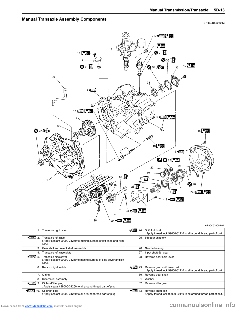
Manual Transaxle Assembly ComponentsS7RS0B5206013
I6RS0C520005-01
1. Transaxle right case 24. Shift fork bolt
: Apply thread lock 99000-32110 to all around thread part of bolt.
2. Transaxle left case : Apply sealant 99000-31260 to mating surface of left case and right
case. 25. 5th gear shift fork
3. Gear shift and select shaft assembly 26. Needle bearing
4. Transaxle left case plate 27. Input shaft 5th gear
5. Transaxle side cover : Apply sealant 99000-31260 to mating surface of side cover and left
case. 28. Reverse gear shift lever
6. Back up light switch 29. Reverse gear shift lever bolt
: Apply thread lock 99000-32110 to all around thread part of bolt.
7. O-ring 30. Reverse gear shaft
8. Differential assembly 31. Washer
9. Oil level/filler plug : Apply sealant 99000-31260 to all around thread part of plug. 32. Reverse idler gear
10. Oil drain plug : Apply sealant 99000-31260 to all around thread part of plug. 33. Reverse shaft bolt
: Apply thread lock 99000-32110 to all around thread part of bolt.
Page 831 of 1496

Downloaded from www.Manualslib.com manuals search engine Manual Transmission/Transaxle: 5B-17
5) Remove gear shift locating bolts (1) with washers,
then take out locating springs and steel balls.
6) Remove back up light switch (2).
7) Remove reverse shaft bolt (2) with washer.
8) Remove case bolts (1) from outside and another bolts from clutch housing side.
9) Tapping left case flanges with plastic hammer, remove left case (3).
10) Pull out reverse gear shaft (1) with washer (2), then take off reverse idler gear (3).
11) Remove reverse gear shift lever bolts (4) and reverse gear shift lever (5).
12) Pull out 5th & reverse gear shift guide shaft (6) together with 5th & reverse gear shift shaft (7). 13) Tapping input shaft end with plastic hammer, push it
out as assembly from case a little, then take out
input shaft assembly (1), countershaft assembly (2),
high speed gear shift shaft (3) and low speed gear
shift shaft (4) all at once.
14) Remove countershaft left bearing outer race from left case (1) using special tool.
Special tool
(A): 09913–70123
15) Remove side bearing retainer bolts.
16) Turn side bearing retainer (1) counterclockwise until it stops, and remove side bearing retainer using 2 flat
end rods (2) or the like.
17) Remove O-ring from side bearing retainer.
I2RH01520032-01
I4RS0A520032-01
I4RS0A520033-01
I2RH01520035-01
(A)
1
I4RH01520021-01
1
2
2
I4RS0A520034-01
Page 833 of 1496

Downloaded from www.Manualslib.com manuals search engine Manual Transmission/Transaxle: 5B-19
4) Make reverse idler gear (1) with reverse gear shift lever (2), insert reverse gear shaft (3) into case (4)
through idler gear and then align “A” in shaft with “B”
in case.
5) Fasten reverse gear shift lever bolts after applying thread lock cement.
: Thread lock cement 99000–32110 (Thread Lock
Cement Super 1322)
Tightening torque
Reverse gear shift lever bolt: 23 N·m (2.3 kgf-m,
17.0 lb-ft)
NOTE
• Make sure that washer (5) has been installed in shaft at above the gear.
• Check to confirm that reverse gear shift lever end has clearance “a” to idler gear
groove.
Distance between lever and idler gear shaft
“a”: 0.5 – 1.0 mm (0.02 – 0.04 in.) 6) Clean mating surfaces of both right and left cases,
apply sealant to right case (2) as shown in the figure
by such amount that its section is 1.5 mm (0.059 in.)
in diameter then mate it with left case (1).
“B”: Sealant 99000–31260 (SUZUKI Bond
No.1217G)
7) Install reverse shaft bolt (4) to which thread lock cement has been applied, with aluminum washer
and tighten it to specified torque.
“A”: Thread lock cement 99000–32110 (Thread
Lock Cement Super 1322)
Tightening torque
Reverse shaft bolt (c): 23 N·m (2.3 kgf-m, 17.0
lb-ft)
8) Tighten case bolts (3) from outside tighten another case bolts from clutch housing side to specified
torque.
Tightening torque
Transaxle case bolt (b): 23 N·m (2.3 kgf-m, 17.0
lb-ft)
I4RS0A520036-01
I3RM0A520043-01