2006 SUBARU IMPREZA torque
[x] Cancel search: torquePage 130 of 365
Instruments and controls 3-17
CONTINUED
is at the proper level but the light remains
on, contact your nearest SUBARU dealer
immediately.
AT OIL TEMPerature
warning light (AT vehi-
cles)
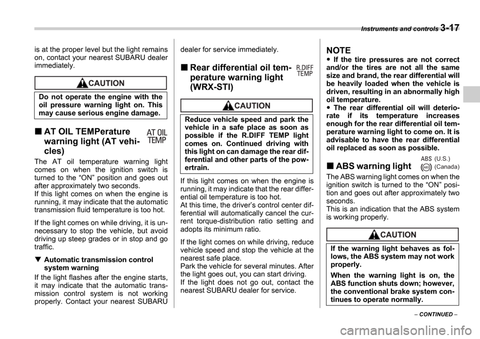
The AT oil temperature warning light
comes on when the ignition switch is
turned to the
ON position and goes out
after approximately two seconds.
If this light comes on when the engine is
running, it may indicate that the automatic
transmission fluid temperature is too hot.
If the light comes on while driving, it is un-
necessary to stop the vehicle, but avoid
driving up steep grades or in stop and go
traffic.
Automatic transmission control
system warning
If the light flashes after the engine starts,
it may indicate that the automatic trans-
mission control system is not working
properly. Contact your nearest SUBARU dealer for service immediately.
Rear differential oil tem-
perature warning light
(WRX-STI)
If this light comes on when the engine is
running, it may indicate that the rear differ-
ential oil temperature is too hot.
At this time, the driver
s control center dif-
ferential will automatically cancel the cur-
rent torque-distribution ratio setting and
adopts its minimum ratio.
If the light comes on while driving, reduce
vehicle speed and stop the vehicle at the
nearest safe place.
Park the vehicle for several minutes. After
the light goes out, you can start driving.
If the light does not go out, contact the
nearest SUBARU dealer for service.
NOTE
If the tire pressures are not correct
and/or the tires are not all the same
size and brand, the rear differential will
be heavily loaded when the vehicle is
driven, resulting in an abnormally high
oil temperature.
The rear differential oil will deterio-
rate if its temperature increases
enough for the rear differential oil tem-
perature warning light to come on. It is
advisable to have the rear differential
oil replaced as soon as possible.
ABS warning light
The ABS warning light comes on when the
ignition switch is turned to the ON posi-
tion and goes out after approximately two
seconds.
This is an indication that the ABS system
is working properly.
Do not operate the engine with the
oil pressure warning light on. This
may cause serious engine damage.
Reduce vehicle speed and park the
vehicle in a safe place as soon as
possible if the R.DIFF TEMP light
comes on. Continued driving with
this light on can damage the rear dif-
ferential and other parts of the pow-
ertrain.
If the warning light behaves as fol-
lows, the ABS system may not work
properly.
When the warning light is on, the
ABS function shuts down; however,
the conventional brake system con-
tinues to operate normally.
(U.S.)
(Canada)
Page 134 of 365
Instruments and controls 3-21
Drivers control center differ-
ential indicator and warning
lights (WRX-STI)
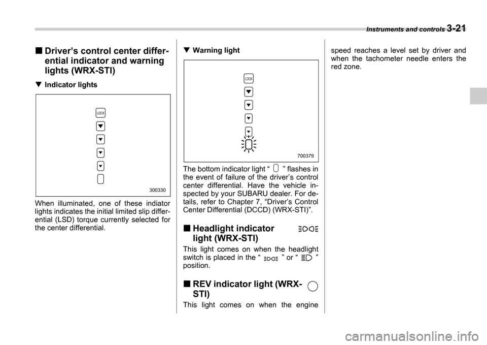
Indicator lights
When illuminated, one of these indiator
lights indicates the initial limited slip differ-
ential (LSD) torque currently selected for
the center differential.
Warning light
The bottom indicator light flashes in
the event of failure of the driver s control
center differential. Have the vehicle in-
spected by your SUBARU dealer. For de-
tails, refer to Chapter 7, Driver s Control
Center Differential (DCCD) (WRX-STI) .
Headlight indicator
light (WRX-STI)
This light comes on when the headlight
switch is placed in the or
position.
REV indicator light (WRX-
STI)
This light comes on when the engine speed reaches a level set by driver and
when the tachometer needle enters the
red zone.
300330
700379
Page 210 of 365
Starting and operating 7-13
CONTINUED
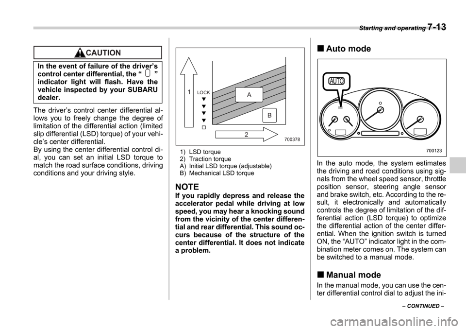
The drivers control center differential al-
lows you to freely change the degree of
limitation of the differential action (limited
slip differential (LSD) torque) of your vehi-
cle s center differential.
By using the center differential control di-
al, you can set an initial LSD torque to
match the road surface conditions, driving
conditions and your driving style.
1) LSD torque
2) Traction torque
A) Initial LSD torque (adjustable)
B) Mechanical LSD torque
NOTE
If you rapidly depress and release the
accelerator pedal while driving at low
speed, you may hear a knocking sound
from the vicinity of the center differen-
tial and rear differential. This sound oc-
curs because of the structure of the
center differential. It does not indicate
a problem.
Auto mode
In the auto mode, the system estimates
the driving and road conditions using sig-
nals from the wheel speed sensor, throttle
position sensor, steering angle sensor
and brake switch, etc. According to the re-
sult, it electronically and automatically
controls the degree of limitation of the dif-
ferential action (LSD torque) to optimize
the differential action of the center differ-
ential. When the ignition switch is turned
ON, the AUTO indicator light in the com-
bination meter comes on. The system can
be switched to a manual mode.
Manual mode
In the manual mode, you can use the cen-
ter differential control dial to adjust the ini-
In the event of failure of the driver
s
control center differential, the
indicator light will flash. Have the
vehicle inspected by your SUBARU
dealer.
700378
LOCK1
2A
B
700123
Page 211 of 365
7-14 Starting and operating
tial LSD torque as desired. When this
mode is selected, the AUTO indicator
light in the combination meter goes off.
Manual switch
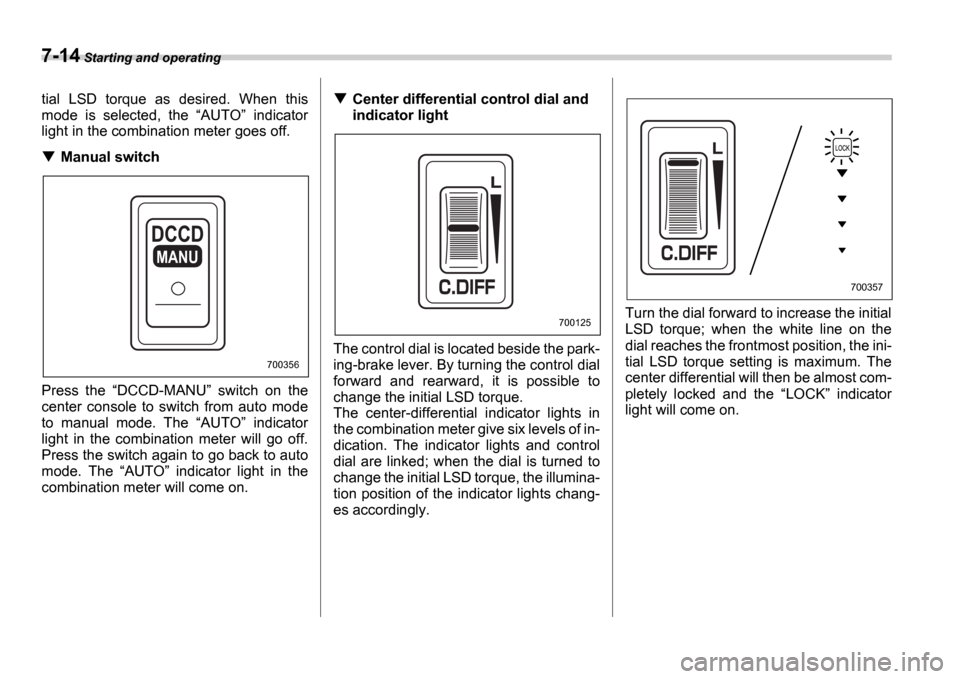
Press the DCCD-MANU switch on the
center console to switch from auto mode
to manual mode. The AUTO indicator
light in the combination meter will go off.
Press the switch again to go back to auto
mode. The AUTO indicator light in the
combination meter will come on.
Center differential control dial and
indicator light
The control dial is located beside the park-
ing-brake lever. By turning the control dial
forward and rearward, it is possible to
change the initial LSD torque.
The center-differential indicator lights in
the combination meter give six levels of in-
dication. The indicator lights and control
dial are linked; when the dial is turned to
change the initial LSD torque, the illumina-
tion position of the indicator lights chang-
es accordingly. Turn the dial forward to increase the initial
LSD torque; when the white line on the
dial reaches the frontmost position, the ini-
tial LSD torque setting is maximum. The
center differential will then be almost com-
pletely locked and the
LOCK indicator
light will come on.
MANU
700356
700125
700357
Page 212 of 365
Starting and operating 7-15
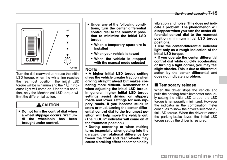
Turn the dial rearward to reduce the initial
LSD torque; when the white line reaches
the rearmost position, the initial LSD
torque will be minimum and the indi-
cator light will come on. Under this condi-
tion, only the Mechanical LSD torque will
limit the differential action.
NOTE
A higher initial LSD torque setting
gives the vehicle greater traction when
driving straight ahead but makes cor-
nering more difficult. Remember this
when adjusting the initial LSD torque.
In general, higher initial LSD torque
settings assist driving on slippery
roads and lower settings for non-slip-
pery roads. If you become stuck in
snow or mud, turning the center differ-
ential control dial to the frontmost po-
sition will help move the vehicle out.
(The LOCK indicator will come on at
the frontmost position.)
During cornering or when making
turns (especially when getting into the
garage), the rotational difference be-
tween the front and rear wheels may
cause a braking effect accompanied by vibration and noise. This does not indi-
cate a problem. The phenomenon will
disappear when you turn the center dif-
ferential control dial to the rearmost
position (minimum initial LSD torque
position).
Use the center-differential indicator
light only as a rough indication of the
initial LSD torque.
If you operate the center differential
control dial while quickly accelerating
or turning a tight corner, you may feel
slight shocks. This is due to differential
action by the center differential and
does not indicate a problem.
Temporary release
When the driver stops the vehicle and
pulls the parking-brake lever after manual-
ly setting the initial LSD torque, the LSD
torque is temporarily minimized. However
the indicator in the combination meter
continues to show the driver s selected ini-
tial LSD torque. When the driver releases
the parking-brake lever, the initial LSD
torque set by the driver is restored.
Do not turn the control dial when
a wheel slippage occurs. Wait un-
til the wheelspin has been
brought under control.
700358
Under any of the following condi-
tions, turn the center differential
control dial to the rearmost posi-
tion to minimize the initial LSD
torque:
When a temporary spare tire is
installed
When your vehicle is towed
When the vehicle is stopped
with the manual mode selected
Page 243 of 365
8-16 Driving tips
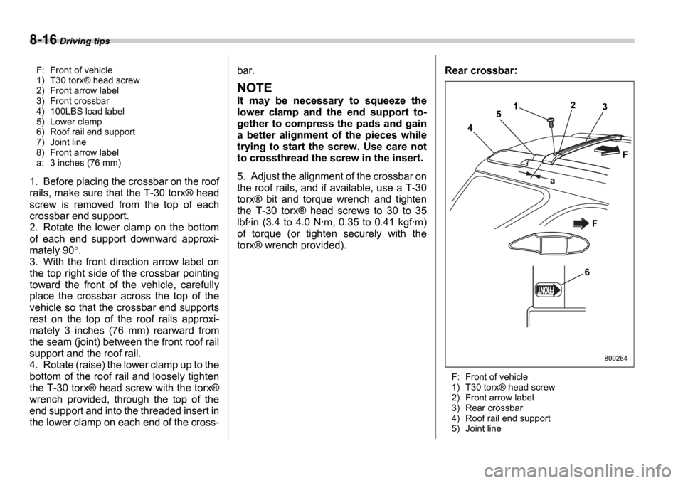
F: Front of vehicle
1) T30 torx Æ head screw
2) Front arrow label
3) Front crossbar
4) 100LBS load label
5) Lower clamp
6) Roof rail end support
7) Joint line
8) Front arrow label
a: 3 inches (76 mm)
1. Before placing the crossbar on the roof
rails, make sure that the T-30 torx Æ head
screw is removed from the top of each
crossbar end support.
2. Rotate the lower clamp on the bottom
of each end support downward approxi-
mately 90 .
3. With the front direction arrow label on
the top right side of the crossbar pointing
toward the front of the vehicle, carefully
place the crossbar across the top of the
vehicle so that the crossbar end supports
rest on the top of the roof rails approxi-
mately 3 inches (76 mm) rearward from
the seam (joint) between the front roof rail
support and the roof rail.
4. Rotate (raise) the lower clamp up to the
bottom of the roof rail and loosely tighten
the T-30 torx Æ head screw with the torx Æ
wrench provided, through the top of the
end support and into the threaded insert in
the lower clamp on each end of the cross- bar.
NOTE
It may be necessary to squeeze the
lower clamp and the end support to-
gether to compress the pads and gain
a better alignment of the pieces while
trying to start the screw. Use care not
to crossthread the screw in the insert.
5. Adjust the alignment of the crossbar on
the roof rails, and if available, use a T-30
torx
Æ bit and torque wrench and tighten
the T-30 torx Æ head screws to 30 to 35
lbf ∑in (3.4 to 4.0 N ∑m, 0.35 to 0.41 kgf ∑m)
of torque (or tighten securely with the
torx Æ wrench provided). Rear crossbar:
F: Front of vehicle
1) T30 torx
Æ head screw
2) Front arrow label
3) Rear crossbar
4) Roof rail end support
5) Joint line
6 3
F
2
1
5
a
4
F
800264
Page 263 of 365
9-8 In case of emergency
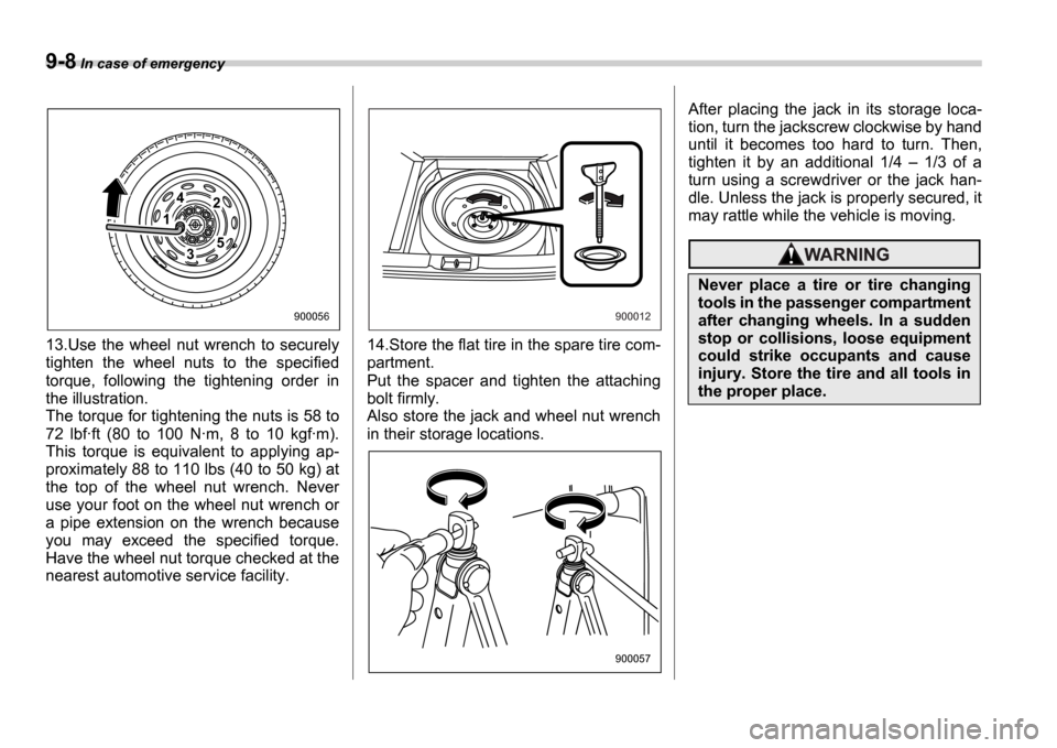
13.Use the wheel nut wrench to securely
tighten the wheel nuts to the specified
torque, following the tightening order in
the illustration.
The torque for tightening the nuts is 58 to
72 lbf ∑ft (80 to 100 N ∑m, 8 to 10 kgf ∑m).
This torque is equivalent to applying ap-
proximately 88 to 110 lbs (40 to 50 kg) at
the top of the wheel nut wrench. Never
use your foot on the wheel nut wrench or
a pipe extension on the wrench because
you may exceed the specified torque.
Have the wheel nut torque checked at the
nearest automotive service facility. 14.Store the flat tire in the spare tire com-
partment.
Put the spacer and tighten the attaching
bolt firmly.
Also store the jack and wheel nut wrench
in their storage locations.After placing the jack in its storage loca-
tion, turn the jackscrew clockwise by hand
until it becomes too hard to turn. Then,
tighten it by an additional 1/4
1/3 of a
turn using a screwdriver or the jack han-
dle. Unless the jack is properly secured, it
may rattle while the vehicle is moving.
1
42
53
900056900012
900057
Never place a tire or tire changing
tools in the passenger compartment
after changing wheels. In a sudden
stop or collisions, loose equipment
could strike occupants and cause
injury. Store the tire and all tools in
the proper place.
Page 313 of 365

11-34 Maintenance and service
placard and to have a speed symbol and
load index matching those shown on the
tire placard.
Using tires of a non-specified size detracts
from controllability, ride comfort, braking
performance, speedometer accuracy and
odometer accuracy. It also creates incor-
rect body-to-tire clearances and inappro-
priately changes the vehicle s ground
clearance.
All four tires must be the same in terms of
manufacturer, brand (tread pattern), con-
struction, and size. You are advised to re-
place the tires with new ones that are
identical to those fitted as standard equip-
ment.
For safe vehicle operation, SUBARU rec-
ommends replacing all four tires at the
same time.
Wheel replacement
When replacing wheels due, for example,
to damage, make sure the replacement
wheels match the specifications of the
wheels that are fitted as standard equip-
ment. Replacement wheels are available
from SUBARU dealers.
NOTE
When any of the wheels is removed
and replaced for tire rotation or to
change a flat tire, always check the
tightness of the wheel nuts after driv-
ing approximately 600 miles (1,000
km). If any nut is loose, tighten it to the
specified torque.
All four tires must be the same in
terms of manufacturer, brand
(tread pattern), construction, de-
gree of wear, speed symbol, load
index and size. Mixing tires of dif-
ferent types, sizes or degrees of
wear can result in damage to vehi-
cle s power train. Use of different
types or sizes of tires can also
dangerously reduce controllabili-
ty and braking performance and
can lead to an accident.
Use only radial tires. Do not use
radial tires together with belted
bias tires and/or bias-ply tires. Do-
ing so can dangerously reduce
controllability, resulting in an ac-
cident.
Use only those wheels that are
specified for your vehicle. Wheels
not meeting specifications could in-
terfere with brake caliper operation
and may cause the tires to rub
against the wheel well housing dur-
ing turns. The resulting loss of vehi-
cle control could lead to an acci-
dent.