Page 19 of 365
16
Combination meter
U.S.-spec. vehicles
WRX
AB
9 87 65
4
3
2
1
000159
1) Fuel gauge (page 3-12)
2) Selector lever position indicator
(page 3-20)
3) Temperature gauge (page 3-13)
4) Tachometer (page 3-12)
5) Speedometer (page 3-11)
6) Odometer and trip meter (page 3-11)
7) Trip meter A/B selection and trip meter reset knob (page 3-11)
8) Outside temperature indicator (page 3-13)
9) Low fuel warning light (page 3-12)
Page 20 of 365
17
CONTINUED
WRX-STI
000160
km/h
AB
11 10 9 8 7 6
5
4
3
2
1
1) Fuel gauge (page 3-8)
2) DCCD indicator (page 3-21)
3) Temperature gauge (page 3-8)
4) Tachometer (page 3-7)
5) REV indicator (page 3-9)
6) Speedometer (page 3-6)
7) Odometer and trip meter (page 3-7)
8) Trip meter A/B selection and trip
meter reset knob (page 3-7)
9) REV setting knob (page 3-9)
10) Outside temperature indicator (page 3-9)
11) Low fuel warning light (page 3-8)
Page 21 of 365
18
Except turbo models
AB
97 65
4
3
2
1
8
000161
1) Fuel gauge (page 3-12)
2) Selector lever position indicator (page 3-20)
3) Temperature gauge (page 3-13)
4) Speedometer (page 3-11)
5) Tachometer (page 3-12)
6) Trip meter A/B selection and trip meter reset knob (page 3-11)
7) Odometer and trip meter (page 3-11)
8) Outside temperature indicator (page 3-13)
9) Low fuel warning light (page 3-12)
Page 22 of 365
19
CONTINUED
Canada-spec. vehicles
WRX
AB
9 8 7 65
4
3
2
1
000162
1) Fuel gauge (page 3-12)
2) Selector lever position indicator
(page 3-20)
3) Temperature gauge (page 3-13)
4) Tachometer (page 3-12)
5) Speedometer (page 3-11)
6) Odometer and trip meter (page 3-11)
7) Trip meter A/B selection and trip meter reset knob (page 3-11)
8) Outside temperature indicator (page 3-13)
9) Low fuel warning light (page 3-12)
Page 23 of 365
20
WRX-STI
000163
AB
11 10 9 8 76
5
4
3
2
1
1) Fuel gauge (page 3-8)
2) DCCD indicator (page 3-21)
3) Temperature gauge (page 3-8)
4) Tachometer (page 3-7)
5) REV indicator (page 3-9)
6) Speedometer (page 3-6)
7) Odometer and trip meter (page 3-7)
8) Trip meter A/B selection and trip
meter reset knob (page 3-7)
9) REV setting knob (page 3-9)
10) Outside temperature indicator (page 3-9)
11) Low fuel warning light (page 3-8)
Page 24 of 365
21
CONTINUED
Except turbo models
AB
9 8 7 6 5
4
3
2
1
000164
1) Fuel gauge (page 3-12)
2) Selector lever position indicator
(page 3-20)
3) Temperature gauge (page 3-13)
4) Speedometer (page 3-11)
5) Tachometer (page 3-12)
6) Trip meter A/B selection and trip meter reset knob (page 3-11)
7) Odometer and trip meter (page 3-11)
8) Outside temperature indicator (page 3-13)
9) Low fuel warning light (page 3-12)
Page 135 of 365

3-22 Instruments and controls
Clock
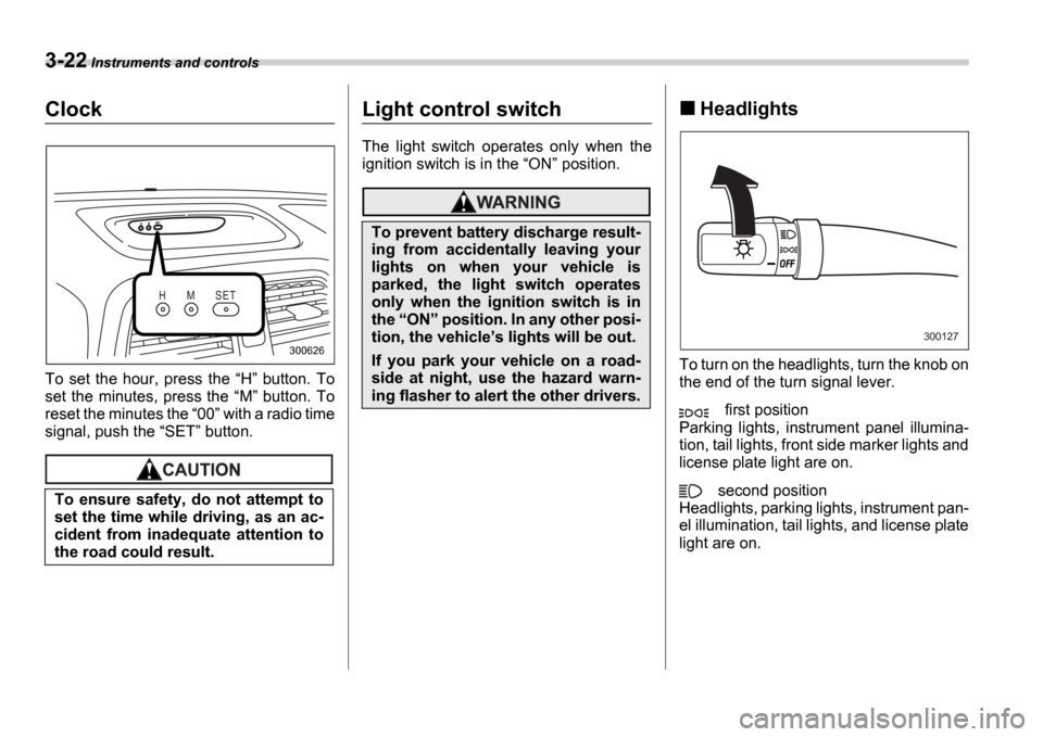
To set the hour, press the H button. To
set the minutes, press the M button. To
reset the minutes the 00 with a radio time
signal, push the SET button.
Light control switch
The light switch operates only when the
ignition switch is in the ON position.
Headlights
To turn on the headlights, turn the knob on
the end of the turn signal lever.
first position
Parking lights, instrument panel illumina-
tion, tail lights, front side marker lights and
license plate light are on.
second position
Headlights, parking lights, instrument pan-
el illumination, tail lights, and license plate
light are on.
To ensure safety, do not attempt to
set the time while driving, as an ac-
cident from inadequate attention to
the road could result.
H M S E T
300626
To prevent battery discharge result-
ing from accidentally leaving your
lights on when your vehicle is
parked, the light switch operates
only when the ignition switch is in
the
ON position. In any other posi-
tion, the vehicle s lights will be out.
If you park your vehicle on a road-
side at night, use the hazard warn-
ing flasher to alert the other drivers.
300127
Page 146 of 365

Instruments and controls 3-33
CONTINUED
cover the sensors with stickers, or other
similar items. Periodically wipe the sen-
sors clean using a piece of dry soft cotton
cloth or an applicator.
Compass calibration
1. For optimum calibration, switch off all
nonessential electrical accessories (rear
window defogger, heater/air conditioning
system, spotlight, etc.) and ensure all
doors are shut.
2. Drive to an open, level area away from
large metallic objects or structures and
make certain the ignition switch is in the ON position.
3. Press and hold the left button for 3 sec-
onds then release, and the compass will
enter the calibration mode. CAL and di-
rection will be displayed.
4. Drive slowly in a circle until CAL dis-
appears from the display (approximately
two or three circles). The compass is now
calibrated.
5. Further calibration may be necessary
should outside. Influences cause the mir-
ror to read inaccurately. You will know that
this has occurred if your compass begins
to read in only limited directions. Should
you encounter this situation, return to step
one of the above procedure and recali-
brate the mirror.
Compass zone adjustment
Compass calibration zones
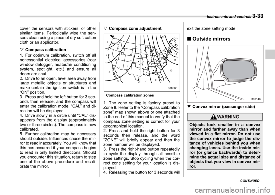
1. The zone setting is factory preset to
Zone 8. Refer to the Compass calibration
zone map shown above or one attached
to the end of this manual to verify that the
compass zone setting is correct for your
geographical location.
2. Press and hold the right button for 3
seconds then release, and the word ZONE will briefly appear and then the
zone number will be displayed.
3. Press the right-hand button repeatedly
to cycle the display through all possible
zone settings. Stop cycling when the cor-
rect zone setting for your location is dis-
played.
4. Releasing the button for 3 seconds will exit the zone setting mode.
Outside mirrors
Convex mirror (passenger side)
10
9
8
7
6
5
4
3
1112
13
300580
Objects look smaller in a convex
mirror and farther away than when
viewed in a flat mirror. Do not use
the convex mirror to judge the dis-
tance of vehicles behind you when
changing lanes. Use the inside mir-
ror (or glance backwards) to deter-
mine the actual size and distance of
objects that you view in convex mir-
ror.
300146