2006 SUBARU IMPREZA maintenance
[x] Cancel search: maintenancePage 327 of 365
11-48 Maintenance and service
3. Replace the bulb with new one.
4. Reconnect the electrical connector. At
this time, use care not to touch the bulb
surface.
5. To install the bulb to the headlight as-
sembly, turn it clockwise until it clicks.
Front turn signal light bulbs
It may be difficult to replace the bulbs.
Have your SUBARU dealer replace the
bulbs if necessary.
Parking light
It may be difficult to replace the bulbs.
Have your SUBARU dealer replace the
bulbs if necessary.
Front fog light
It may be difficult to replace the bulbs.
Have your SUBARU dealer replace the
bulbs if necessary.
Rear combination lights
Sedan
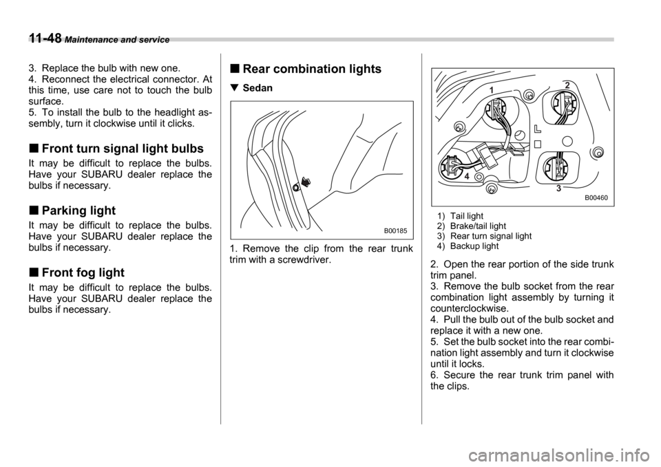
1. Remove the clip from the rear trunk
trim with a screwdriver.
1) Tail light
2) Brake/tail light
3) Rear turn signal light
4) Backup light
2. Open the rear portion of the side trunk
trim panel.
3. Remove the bulb socket from the rear
combination light assembly by turning it
counterclockwise.
4. Pull the bulb out of the bulb socket and
replace it with a new one.
5. Set the bulb socket into the rear combi-
nation light assembly and turn it clockwise
until it locks.
6. Secure the rear trunk trim panel with
the clips.
B00185
1 2
3
4
B00460
Page 328 of 365
Maintenance and service 11-49
CONTINUED
Wagon
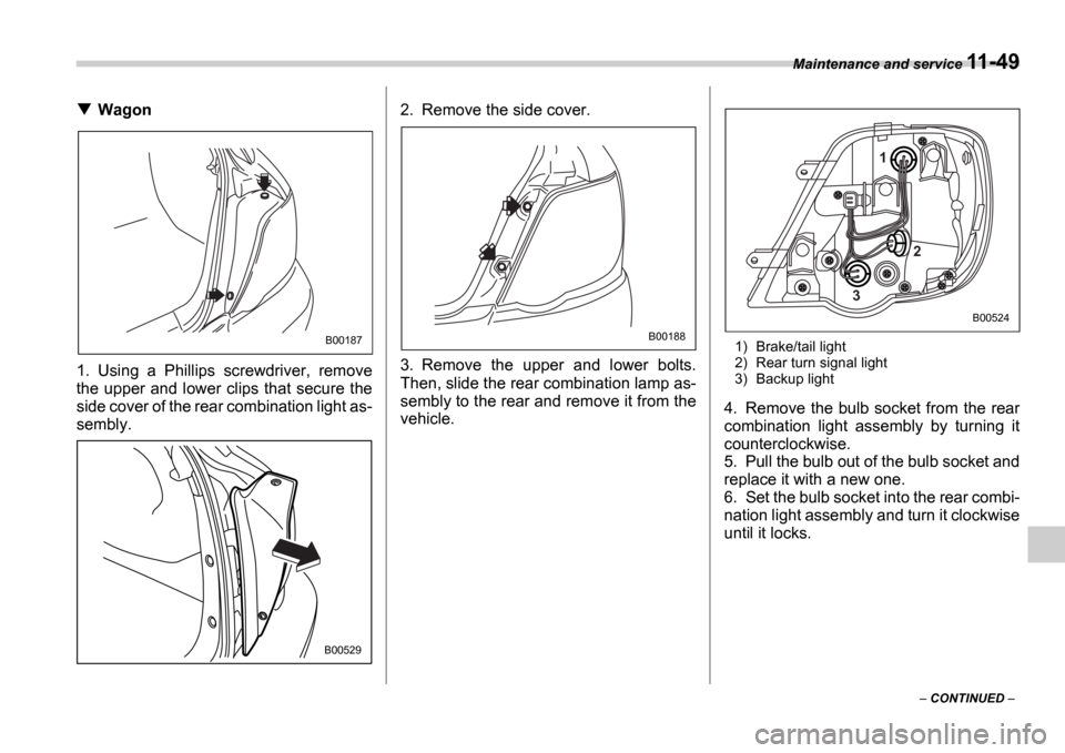
1. Using a Phillips screwdriver, remove
the upper and lower clips that secure the
side cover of the rear combination light as-
sembly. 2. Remove the side cover.
3. Remove the upper and lower bolts.
Then, slide the rear combination lamp as-
sembly to the rear and remove it from the
vehicle.
1) Brake/tail light
2) Rear turn signal light
3) Backup light
4. Remove the bulb socket from the rear
combination light assembly by turning it
counterclockwise.
5. Pull the bulb out of the bulb socket and
replace it with a new one.
6. Set the bulb socket into the rear combi-
nation light assembly and turn it clockwise
until it locks.
B00187
B00529
B00188
1
3 2
B00524
Page 329 of 365
11-50 Maintenance and service
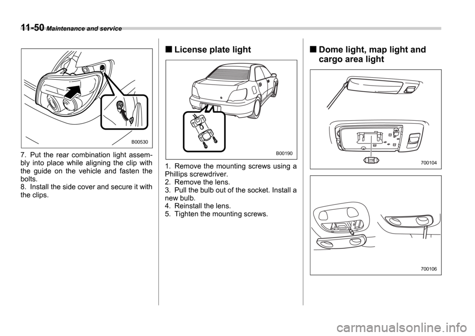
7. Put the rear combination light assem-
bly into place while aligning the clip with
the guide on the vehicle and fasten the
bolts.
8. Install the side cover and secure it with
the clips.
License plate light
1. Remove the mounting screws using a
Phillips screwdriver.
2. Remove the lens.
3. Pull the bulb out of the socket. Install a
new bulb.
4. Reinstall the lens.
5. Tighten the mounting screws.
Dome light, map light and
cargo area light
B00530
B00190
700104
700106
Page 330 of 365
Maintenance and service 11-51
CONTINUED
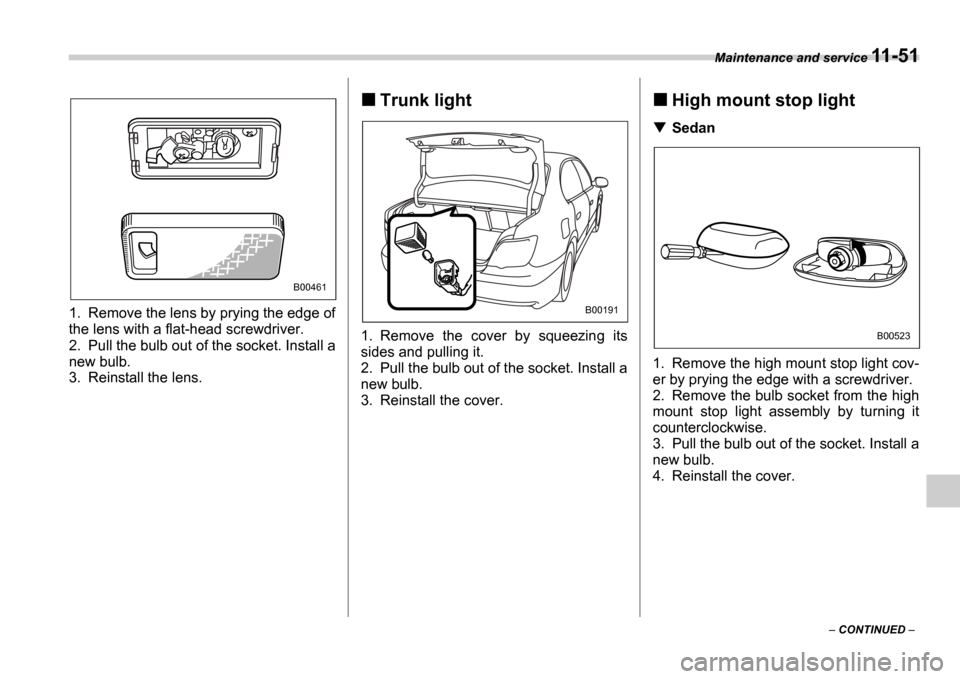
1. Remove the lens by prying the edge of
the lens with a flat-head screwdriver.
2. Pull the bulb out of the socket. Install a
new bulb.
3. Reinstall the lens.
Trunk light0
1. Remove the cover by squeezing its
sides and pulling it.
2. Pull the bulb out of the socket. Install a
new bulb.
3. Reinstall the cover.
High mount stop light
Sedan
1. Remove the high mount stop light cov-
er by prying the edge with a screwdriver.
2. Remove the bulb socket from the high
mount stop light assembly by turning it
counterclockwise.
3. Pull the bulb out of the socket. Install a
new bulb.
4. Reinstall the cover.
B00461
B00191
B00523
Page 331 of 365
11-52 Maintenance and service
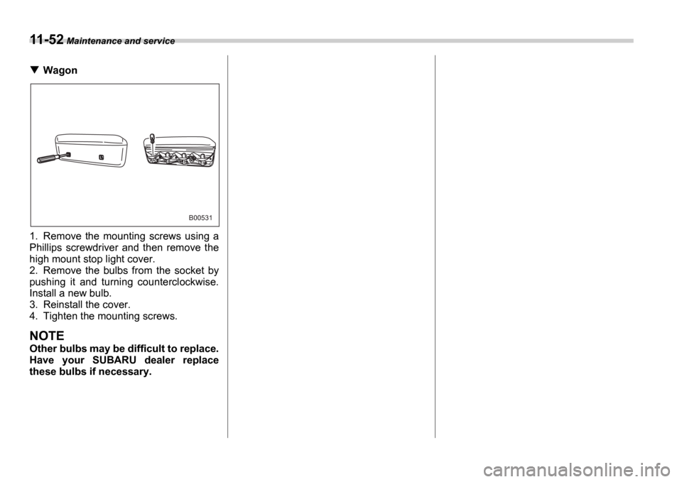
Wagon
1. Remove the mounting screws using a
Phillips screwdriver and then remove the
high mount stop light cover.
2. Remove the bulbs from the socket by
pushing it and turning counterclockwise.
Install a new bulb.
3. Reinstall the cover.
4. Tighten the mounting screws.
NOTE
Other bulbs may be difficult to replace.
Have your SUBARU dealer replace
these bulbs if necessary.
B00531
Page 342 of 365
13
Consumer information and Reporting safety defects
Tire information .................................................. 13-2
Tire labeling ..................................... ........................ 13-2
Recommended tire inflation pressure ............... ... 13-5
Glossary of tire terminology ...................... ............ 13-6
Tire care maintenance and safety practices ..... 13-7
Vehicle load limit how to determine ................... 13-8
Determining compatibility of tire and vehicle load capacities ................................... ................... 13-10
Adverse safety consequences of overloading on
handling and stopping and on tires ................ ... 13-11
Steps for Determining Correct Load Limit .......... . 13-11
Uniform tire quality grading standards ............ 13-12
Treadwear ......................................... ....................... 13-12
Traction AA, A, B, C .............................. .................. 13-12
Temperature A, B, C ............................... ................ 13-12
Reporting safety defects (USA) .................... ..... 13-13
Page 348 of 365
Consumer information and Reporting safety defects 13-7
CONTINUED
asymmetrical tire that has a particu-
lar side that must always face out-
ward when mounting on a vehicle.
Accessory weight
The combined weight (in excess of
those standard items which may be
replaced) of floor mats, leather seats
and cross bars to the extent that these
items are available as factory-in-
stalled equipment (whether installed
or not).
Curb weight
The weight of a motor vehicle with
standard equipment including the
maximum capacity of fuel, oil, and
coolant and air conditioning.
Maximum loaded vehicle weight
The sum of curb weight, accessory
weight, vehicle capacity weight and
production options weight.
Normal occupant weight
150 lbs (68 kg) times the number of
occupants (3 occupants).
Occupant distribution
Distribution of occupants in a vehicle,
2 in front, 1 in rear seat.
Production options weight
The combined weight of those in-
stalled regular production options weighing over 5.1 lbs (2.3 kg) in ex-
cess of those standards items which
they replace, not previously consid-
ered in curb weight or accessory
weight.
Vehicle capacity weight
The total weight of cargo, luggage
and occupants that can be added to
the vehicle.
Vehicle maximum load on a tire
Load on an individual tire that is deter-
mined by distributing to each axle its
share of the maximum loaded vehicle
weight and dividing by two.
Vehicle normal load on a tire
Load on an individual tire that is deter-
mined by distributing to each axle its
share of the curb weight, accessory
weight, and normal occupant weight
and dividing by two.
Tire care maintenance and
safety practices
Check on a daily basis that the tires
are free from serious damage, nails,
and stones. At the same time, check
the tires for abnormal wear.
Inspect the tire tread regularly and
replace the tires before their tread wear indicators become visible. When
a tire
s tread wear indicator becomes
visible, the tire is worn beyond the ac-
ceptable limit and must be replaced
immediately. With a tire in this condi-
tion, driving at even low speeds in wet
weather can cause the vehicle to hy-
droplane. Possible resulting loss of
vehicle control can lead to an acci-
dent.
To maximize the life of each tire and
ensure that the tires wear uniformly, it
is best to rotate the tires every 7,500
miles (12,500 km). Rotating the tires
involves switching the front and rear
tires on the right-hand side of the ve-
hicle and similarly switching the front
and rear tires on the left-hand side of
the vehicle. (Each tire must be kept on
its original side of the vehicle.) Re-
place any damaged or unevenly worn
tire at the time of rotation. After tire ro-
tation, adjust the tire pressures and
make sure the wheel nuts are correct-
ly tightened. A tightening torque spec-
ification and a tightening sequence
specification for the wheel nuts can be
found Flat tires section in chapter 9.
Page 360 of 365
Index 14-5
I
Ignition switch ..................................... ................................ 3-3
Illuminated entry .................................. ............................... 2-8
Illumination brightness control .................... ...................... 3-25
Immobilizer ........................................ ................................. 2-3
Indicator light
High beam ......................................... .......................... 3-20
Selector lever position .............................. ................... 3-20
Turn signal ........................................ ........................... 3-20
Inside mirror ...................................... ............................... 3-32
Intercooler water spray .............................. ..................... 11-35
Switch ............................................. ............................. 3-31
Warning light ..................................... ........................... 3-19
Interior light .................................... ..................................... 6-2
Internal trunk lid release handle ................... .................... 2-21
J
Jack and jack handle ................................... ..................... 9-16
Jump starting ....................................... ............................... 9-9
K
Key Interlock release ................................... ......................... 3-5
Number ............................................ .............................. 2-2
Reminder chime ..................................... ....................... 3-5
Keys ............................................... .................................... 2-2
L
Leather seat materials .............................. ........................ 10-5
Light Cargo area ........................................ .................. 6-2, 11-50Dome ..............................................
.................... 6-2, 11-50
Map ............................................... ...................... 6-2, 11-50
Light control switch ................................. .......................... 3-22
Limited slip differential (LSD) ................... ......................... 7-20
Loading your vehicle ................................ ......................... 8-12
LSD (Limited slip differential) .................... ........................ 7-20
M
Main fuse .......................................... .............................. 11-43
Maintenance Precautions ......................................... ......................... 11-3
Schedule ........................................... ........................... 11-3
Seatbelt .......................................... .............................. 1-18
Tools .............................................. .............................. 9-16
Malfunction indicator lamp (Check Engine light) ....... ........ 3-16
Manual climate control system .......................... ................. 4-3
Manual transmission 5 speeds ........................................... ........................... 7-11
6 speeds ........................................... ............................. 7-9
Map light ......................................... ......................... 6-2, 11-50
Maximum load limits ................................ ......................... 8-20
Meters and gauges ................................... ................. 3-6, 3-11
Mirrors ............................................ ................................... 3-32
Moonroof .......................................... ........................ 2-24, 9-15
N
New vehicle break-in driving the first 1,000 miles (1,600 km) ......................................... .............................. 8-2
O
Odometer/Trip meter ............................... .................. 3-7, 3-11