2006 SUBARU IMPREZA warning light
[x] Cancel search: warning lightPage 83 of 365

1-56 Seat, seatbelt and SRS airbags
Examples of the types of accidents
in which the SRS side airbag will ba-
sically not deploy.
1) The vehicle is involved in a frontal colli-
sion with another vehicle (moving or sta-
tionary).
2) The vehicle is struck from behind.
The SRS side airbag is basically not de-
signed to deploy if the vehicle is involved
in a frontal collision or is struck from be-
hind. Examples of such accidents are il-
lustrated.
1) First impact
2) Second impact
In an accident where the vehicle is struck
from the side more than once, the SRS
side airbag deploys only once on the first
impact.
Example: In the case of a double side im-
pact collision, first with one vehicle and
immediately followed by another from the
same direction, once the SRS side airbag
is activated on the first impact, it will not be
activated on the second.
SRS airbag system monitors
A diagnostic system continually monitors
the readiness of the SRS airbag system
(including front seatbelt pretensioners)
while the vehicle is being driven. The SRS
airbag system warning light AIRBAG will
show normal system operation by lighting
for approximately 6 seconds when the ig-
nition switch is turned to the ON position.
The following components are monitored
by the indicator:
Front sub sensor (Right-hand side)
Front sub sensor (Left-hand side)
Airbag control module (including impact
sensors)
Frontal airbag module (Driver s side)
Frontal airbag module (Front passen-
ger s side)
1 2
100703
2
1
100629
100291
Page 84 of 365
Seat, seatbelt and SRS airbags 1-57
CONTINUED
Side airbag sensor (Center pillar right
hand side)
Side airbag sensor (Center pillar left
hand side)
Side airbag module (Driver s side)
Side airbag module (Front passenger s
side)
Seatbelt pretensioner (Driver s side)
Seatbelt pretensioner (Front passen-
ger s side)
Seatbelt buckle switch (Driver s side)
Seatbelt buckle switch (Front passen-
ger s side)
Driver s seat position sensor
Front passenger s seatbelt tension sen-
sor
Front passenger s occupant detection
system weight sensor
Front passenger s occupant detection
control module
Front passenger s frontal airbag ON
and OFF indicator
All related wiring
SRS airbag system servicing
If the warning light exhibits any of
the following conditions, there may
be a malfunction in the seatbelt pre-
tensioners and/or SRS airbag sys-
tem. Immediately take your vehicle
to your nearest SUBARU dealer to
have the system checked. Unless
checked and properly repaired, the
seatbelt pretensioners and/or SRS
airbag will not operate properly in
the event of a collision, which may
increase the risk of injury.
Flashing or flickering of the warn-
ing light
No illumination of the warning
light when the ignition switch is
first turned to the ON position
Continuous illumination of the
warning light
Illumination of the warning light
while driving
When discarding an airbag mod-
ule or scrapping the entire vehicle
damaged by a collision, consult
your SUBARU dealer.
The SRS airbag has no user-ser-
viceable parts. Do not use electri-
cal test equipment on any circuit
related to the SRS airbag system.
For required servicing of the SRS
airbag, see your nearest SUBARU
dealer. Tampering with or discon-
necting the system s wiring could
result in accidental inflation of the
SRS airbag or could make the sys-
tem inoperative, which may result
in serious injury. The wiring har-
nesses of the SRS airbag system
are covered with yellow insulation
and system connectors are yellow
for easy identification.
Page 114 of 365

3
Instruments and controls
Ignition switch .................................................... 3-3
LOCK .............................................. ......................... 3-3
ACC ............................................... ........................... 3-4
ON ................................................ ............................ 3-4
START ............................................. ......................... 3-4
Key reminder chime ................................ ............... 3-5
Ignition switch light ............................. ................... 3-5
Key interlock release (AT vehicles only) .......... .... 3-5
Hazard warning flasher ............................ .......... 3-6
Meters and gauges (WRX-STI) ....................... ... 3-6
Combination meter illumination .................... ........ 3-6
Cancelling sequential illumination of the combination meter ................................. .............. 3-6
Speedometer ....................................... .................... 3-6
Odometer/Trip meter ............................... ............... 3-7
Tachometer ........................................ ..................... 3-7
Fuel gauge ........................................ ....................... 3-8
Temperature gauge ................................. ............... 3-8
Outside temperature indicator ..................... ......... 3-9
REV indicator light and buzzer (WRX-STI) ....... 3-9 Setting the alarm-level engine speed .............. ..... 3-10
Deactivating the REV alarm system ................. ..... 3-11
Meters and gauges (Except WRX-STI) ............. 3-1 1
Speedometer ....................................... .................... 3-11
Odometer/Trip meter ............................... ............... 3-11
Tachometer ........................................ ..................... 3-12
Fuel gauge ........................................ ....................... 3-12
Temperature gauge ................................. ............... 3-13
Outside temperature indicator ..................... ......... 3-13Warning and indicator lights ......................
....... 3-14
Seatbelt warning light and chime .................. ........ 3-14
SRS airbag system warning light ................... ....... 3-15
Front passenger s frontal airbag ON and OFF
indicators ........................................ ...................... 3-15
CHECK ENGINE warning light/Malfunction indicator lamp .................................... ................... 3-16
Charge warning light .............................. ................ 3-16
Oil pressure warning light ........................ ............. 3-16
AT OIL TEMPerature warning light (AT vehicles) ..................................... .................... 3-17
Rear differential oil temperature warning light (WRX-STI) ......................................... ..................... 3-17
ABS warning light ................................. .................. 3-17
Brake system warning light ........................ ........... 3-18
Door open warning light ........................... ............. 3-19
All-Wheel Drive warning light (AWD AT vehicles
if equipped) ..................................... ................... 3-19
Intercooler water spray warning light (WRX-STI) ......................................... ..................... 3-19
Selector lever position indicator (AT vehicles) ... . 3-20
Turn signal indicator lights ...................... .............. 3-20
High beam indicator light ......................... .............. 3-20
Cruise control indicator light .................... ............. 3-20
Cruise control set indicator light ................ .......... 3-20
Driver s control center differential auto indicator
light (WRX-STI) ................................... .................. 3-20
Driver s control center differential indicator and
warning lights (WRX-STI) .......................... .......... 3-21
Headlight indicator light (WRX-STI) ............... ....... 3-21
REV indicator light (WRX-STI) ..................... .......... 3-21
Page 119 of 365
3-6 Instruments and controls
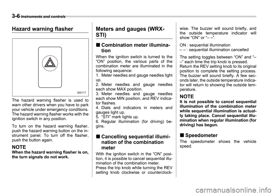
Hazard warning flasher
The hazard warning flasher is used to
warn other drivers when you have to park
your vehicle under emergency conditions.
The hazard warning flasher works with the
ignition switch in any position.
To turn on the hazard warning flasher,
push the hazard warning button on the in-
strument panel. To turn off the flasher,
push the button again.
NOTE
When the hazard warning flasher is on,
the turn signals do not work.
Meters and gauges (WRX-
STI)
Combination meter illumina-
tion
When the ignition switch is turned to the ON position, the various parts of the
combination meter are illuminated in the
following sequence:
1. Meter needles and gauge needles light
up.
2. Meter needles and gauge needles
each show MAX position.
3. Meter needles and gauge needles
each show MIN position, and REV indica-
tor flashes.
4. Dials and indicators in meters and
gauges light up.
5. STI mark lights up.
6. Regular illumination (for driving) be-
gins.
Cancelling sequential illumi-
nation of the combination
meter
With the ignition switch in the ON posi-
tion, it is possible to cancel sequential illu-
mination of the combination meter.
Press the trip knob while turning the REV
setting knob clockwise or counterclock- wise. The buzzer will sound briefly, and
the outside temperature indicator will
show
ON or .
ON : sequential illumination : sequential illumination cancelled
The setting toggles between ON and
each time the trip knob is pressed.
Return the REV setting knob to its original
position to complete the setting process.
The buzzer will sound briefly. A few sec-
onds later, the outside temperature indica-
tor will return to showing the outside tem-
perature.
NOTE
It is not possible to cancel sequential
illumination of the combination meter
while sequential illumination is actual-
ly taking place. Cancel sequential illu-
mination when regular illumination (for
driving) has begun.
Speedometer
The speedometer shows the vehicle
speed.
300117
Page 121 of 365
3-8 Instruments and controls
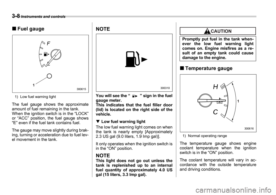
Fuel gauge
1) Low fuel warning light
The fuel gauge shows the approximate
amount of fuel remaining in the tank.
When the ignition switch is in the LOCK
or ACC position, the fuel gauge shows
E even if the fuel tank contains fuel.
The gauge may move slightly during brak-
ing, turning or acceleration due to fuel lev-
el movement in the tank.
NOTE
You will see the sign in the fuel
gauge meter.
This indicates that the fuel filler door
(lid) is located on the right side of the
vehicle.
Low fuel warning light
The low fuel warning light comes on when
the tank is nearly empty [Approximately
2.3 US gal (9.0 liters, 1.9 Imp gal)].
It only operates when the ignition switch is
in the ON position.
NOTE
This light does not go out unless the
tank is replenished up to an internal
fuel quantity of approximately 4.0 US
gal (15 liters, 3.3 Imp gal).
Temperature gauge
1) Normal operating range
The temperature gauge shows engine
coolant temperature when the ignition
switch is in the ON position.
The coolant temperature will vary in ac-
cordance with the outside temperature
and driving conditions.
1300615300310
Promptly put fuel in the tank when-
ever the low fuel warning light
comes on. Engine misfires as a re-
sult of an empty tank could cause
damage to the engine.
1
300616
Page 122 of 365
Instruments and controls 3-9
CONTINUED
We recommend that you drive moderately
until the pointer of the temperature gauge
reaches near the middle of the range. En-
gine operation is optimum with the engine
coolant at this temperature range and high
revving operation when the engine is not
warmed up enough should be avoided.
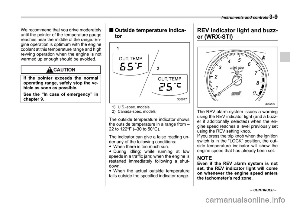
Outside temperature indica-
tor
1) U.S.-spec. models
2) Canada-spec. models
The outside temperature indicator shows
the outside temperature in a range from
22 to 122 F ( 30 to 50 C).
The indicator can give a false reading un-
der any of the following conditions:
When there is too much sun.
During idling; while running at low
speeds in a traffic jam; when the engine is
restarted immediately following a shut-
down.
When the actual outside temperature
falls outside the specified indicator range.
REV indicator light and buzz-
er (WRX-STI)
The REV alarm system issues a warning
using the REV indicator light (and a buzz-
er if additionally selected) when the en-
gine speed reaches a level previously set
using the REV setting knob.
If you press the trip knob when the ignition
switch is in the LOCK position, the out-
side temperature indicator will show the
engine speed that has already been set.
NOTE
Even if the REV alarm system is not
set, the REV indicator light will come
on whenever the engine speed enters
the tachometer s red zone.
If the pointer exceeds the normal
operating range, safely stop the ve-
hicle as soon as possible.
See the
In case of emergency in
chapter 9.
1
2
300617
300239
Page 123 of 365
3-10 Instruments and controls
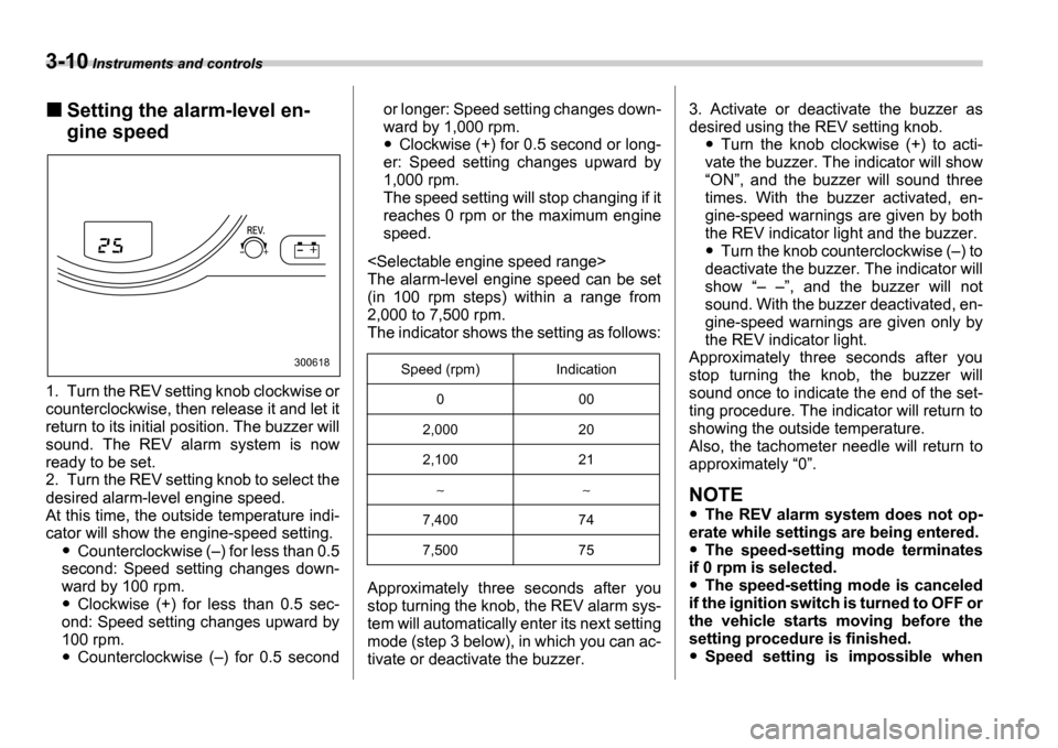
Setting the alarm-level en-
gine speed
1. Turn the REV setting knob clockwise or
counterclockwise, then release it and let it
return to its initial position. The buzzer will
sound. The REV alarm system is now
ready to be set.
2. Turn the REV setting knob to select the
desired alarm-level engine speed.
At this time, the outside temperature indi-
cator will show the engine-speed setting.
Counterclockwise ( ) for less than 0.5
second: Speed setting changes down-
ward by 100 rpm.
Clockwise (+) for less than 0.5 sec-
ond: Speed setting changes upward by
100 rpm.
Counterclockwise ( ) for 0.5 second or longer: Speed setting changes down-
ward by 1,000 rpm.
Clockwise (+) for 0.5 second or long-
er: Speed setting changes upward by
1,000 rpm.
The speed setting will stop changing if it
reaches 0 rpm or the maximum engine
speed.
The alarm-level engine speed can be set
(in 100 rpm steps) within a range from
2,000 to 7,500 rpm.
The indicator shows the setting as follows:
Approximately three seconds after you
stop turning the knob, the REV alarm sys-
tem will automatically enter its next setting
mode (step 3 below), in which you can ac-
tivate or deactivate the buzzer. 3. Activate or deactivate the buzzer as
desired using the REV setting knob.Turn the knob clockwise (+) to acti-
vate the buzzer. The indicator will show ON , and the buzzer will sound three
times. With the buzzer activated, en-
gine-speed warnings are given by both
the REV indicator light and the buzzer.
Turn the knob counterclockwise ( ) to
deactivate the buzzer. The indicator will
show , and the buzzer will not
sound. With the buzzer deactivated, en-
gine-speed warnings are given only by
the REV indicator light.
Approximately three seconds after you
stop turning the knob, the buzzer will
sound once to indicate the end of the set-
ting procedure. The indicator will return to
showing the outside temperature.
Also, the tachometer needle will return to
approximately 0 .
NOTE
The REV alarm system does not op-
erate while settings are being entered.
The speed-setting mode terminates
if 0 rpm is selected.
The speed-setting mode is canceled
if the ignition switch is turned to OFF or
the vehicle starts moving before the
setting procedure is finished.
Speed setting is impossible when
300618Speed (rpm) Indication
0 00
2,000 20
2,100 21
7,400 74
7,500 75
Page 125 of 365
3-12 Instruments and controls
NOTE
If the connection between the combi-
nation meter and battery is broken for
any reason such as vehicle mainte-
nance or fuse replacement, the data re-
corded on the trip meter will be lost.
Tachometer
The tachometer shows the engine speed
in thousands of revolutions per minute.
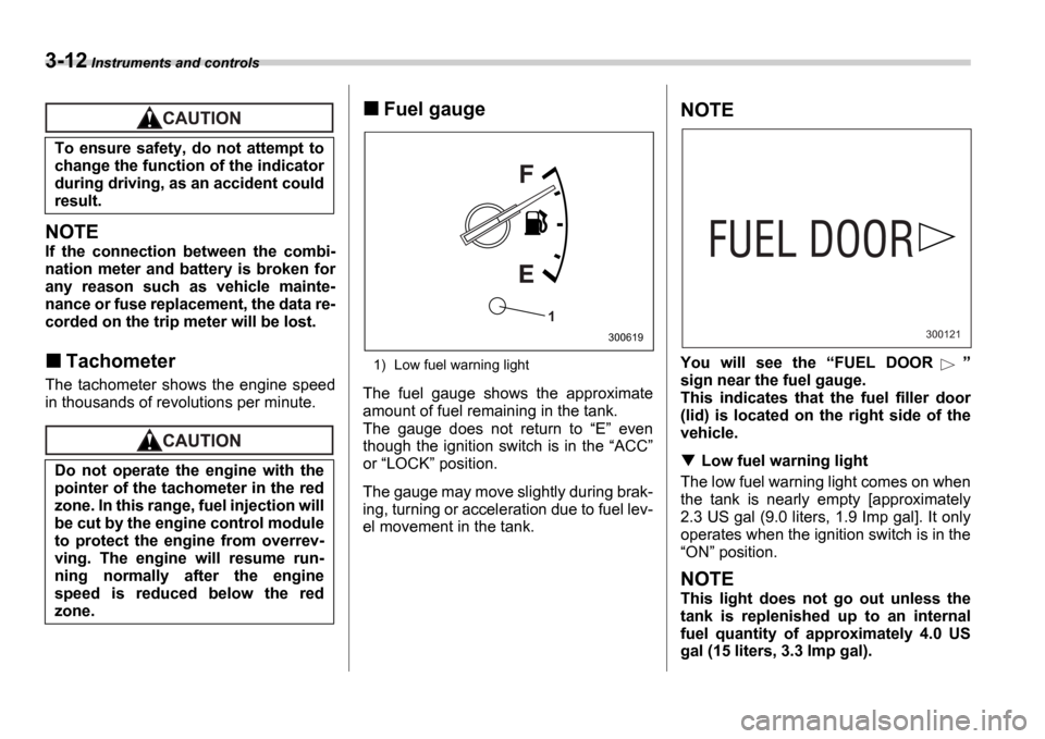
Fuel gauge
1) Low fuel warning light
The fuel gauge shows the approximate
amount of fuel remaining in the tank.
The gauge does not return to E even
though the ignition switch is in the ACC
or LOCK position.
The gauge may move slightly during brak-
ing, turning or acceleration due to fuel lev-
el movement in the tank.
NOTE
You will see the FUEL DOOR
sign near the fuel gauge.
This indicates that the fuel filler door
(lid) is located on the right side of the
vehicle.
Low fuel warning light
The low fuel warning light comes on when
the tank is nearly empty [approximately
2.3 US gal (9.0 liters, 1.9 Imp gal]. It only
operates when the ignition switch is in the ON position.
NOTE
This light does not go out unless the
tank is replenished up to an internal
fuel quantity of approximately 4.0 US
gal (15 liters, 3.3 Imp gal).
To ensure safety, do not attempt to
change the function of the indicator
during driving, as an accident could
result.
Do not operate the engine with the
pointer of the tachometer in the red
zone. In this range, fuel injection will
be cut by the engine control module
to protect the engine from overrev-
ving. The engine will resume run-
ning normally after the engine
speed is reduced below the red
zone.
1
300619300121