2006 SUBARU IMPREZA fuel
[x] Cancel search: fuelPage 114 of 365
3
Instruments and controls
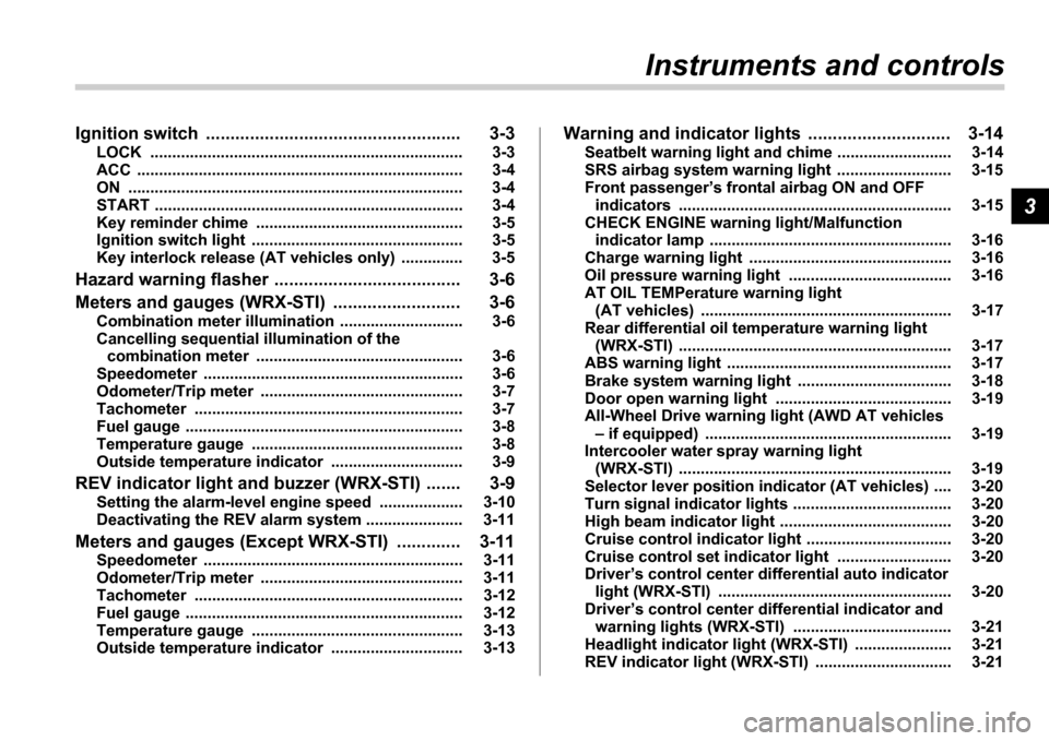
Ignition switch .................................................... 3-3
LOCK .............................................. ......................... 3-3
ACC ............................................... ........................... 3-4
ON ................................................ ............................ 3-4
START ............................................. ......................... 3-4
Key reminder chime ................................ ............... 3-5
Ignition switch light ............................. ................... 3-5
Key interlock release (AT vehicles only) .......... .... 3-5
Hazard warning flasher ............................ .......... 3-6
Meters and gauges (WRX-STI) ....................... ... 3-6
Combination meter illumination .................... ........ 3-6
Cancelling sequential illumination of the combination meter ................................. .............. 3-6
Speedometer ....................................... .................... 3-6
Odometer/Trip meter ............................... ............... 3-7
Tachometer ........................................ ..................... 3-7
Fuel gauge ........................................ ....................... 3-8
Temperature gauge ................................. ............... 3-8
Outside temperature indicator ..................... ......... 3-9
REV indicator light and buzzer (WRX-STI) ....... 3-9 Setting the alarm-level engine speed .............. ..... 3-10
Deactivating the REV alarm system ................. ..... 3-11
Meters and gauges (Except WRX-STI) ............. 3-1 1
Speedometer ....................................... .................... 3-11
Odometer/Trip meter ............................... ............... 3-11
Tachometer ........................................ ..................... 3-12
Fuel gauge ........................................ ....................... 3-12
Temperature gauge ................................. ............... 3-13
Outside temperature indicator ..................... ......... 3-13Warning and indicator lights ......................
....... 3-14
Seatbelt warning light and chime .................. ........ 3-14
SRS airbag system warning light ................... ....... 3-15
Front passenger s frontal airbag ON and OFF
indicators ........................................ ...................... 3-15
CHECK ENGINE warning light/Malfunction indicator lamp .................................... ................... 3-16
Charge warning light .............................. ................ 3-16
Oil pressure warning light ........................ ............. 3-16
AT OIL TEMPerature warning light (AT vehicles) ..................................... .................... 3-17
Rear differential oil temperature warning light (WRX-STI) ......................................... ..................... 3-17
ABS warning light ................................. .................. 3-17
Brake system warning light ........................ ........... 3-18
Door open warning light ........................... ............. 3-19
All-Wheel Drive warning light (AWD AT vehicles
if equipped) ..................................... ................... 3-19
Intercooler water spray warning light (WRX-STI) ......................................... ..................... 3-19
Selector lever position indicator (AT vehicles) ... . 3-20
Turn signal indicator lights ...................... .............. 3-20
High beam indicator light ......................... .............. 3-20
Cruise control indicator light .................... ............. 3-20
Cruise control set indicator light ................ .......... 3-20
Driver s control center differential auto indicator
light (WRX-STI) ................................... .................. 3-20
Driver s control center differential indicator and
warning lights (WRX-STI) .......................... .......... 3-21
Headlight indicator light (WRX-STI) ............... ....... 3-21
REV indicator light (WRX-STI) ..................... .......... 3-21
Page 120 of 365
Instruments and controls 3-7
CONTINUED
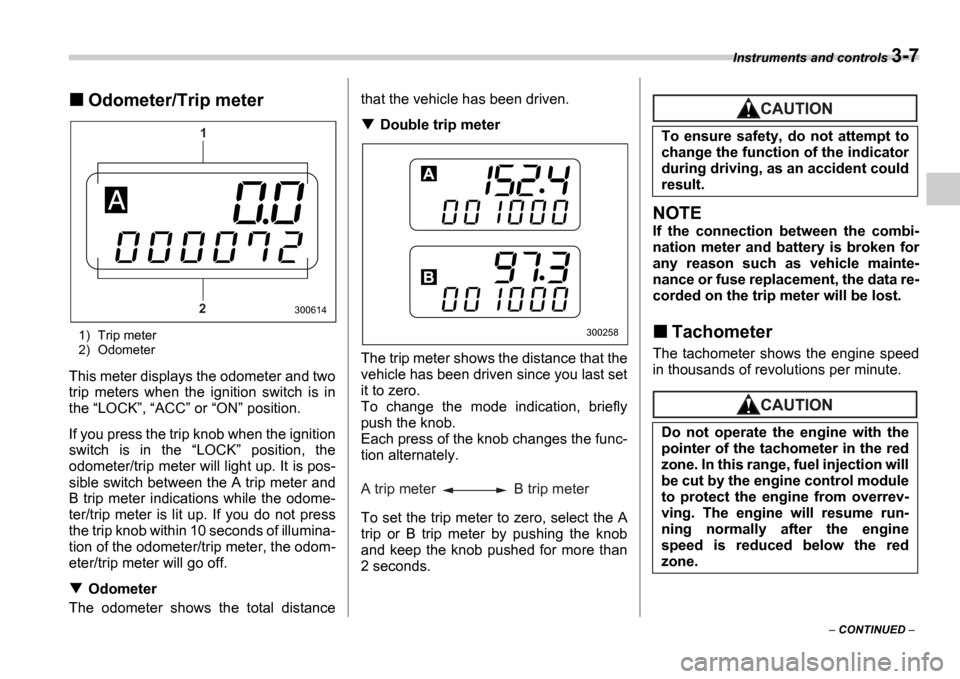
Odometer/Trip meter
1) Trip meter
2) Odometer
This meter displays the odometer and two
trip meters when the ignition switch is in
the LOCK , ACC or ON position.
If you press the trip knob when the ignition
switch is in the LOCK position, the
odometer/trip meter will light up. It is pos-
sible switch between the A trip meter and
B trip meter indications while the odome-
ter/trip meter is lit up. If you do not press
the trip knob within 10 seconds of illumina-
tion of the odometer/trip meter, the odom-
eter/trip meter will go off.
Odometer
The odometer shows the total distance that the vehicle has been driven.
Double trip meter
The trip meter shows the distance that the
vehicle has been driven since you last set
it to zero.
To change the mode indication, briefly
push the knob.
Each press of the knob changes the func-
tion alternately.
To set the trip meter to zero, select the A
trip or B trip meter by pushing the knob
and keep the knob pushed for more than
2 seconds.
NOTE
If the connection between the combi-
nation meter and battery is broken for
any reason such as vehicle mainte-
nance or fuse replacement, the data re-
corded on the trip meter will be lost.
Tachometer
The tachometer shows the engine speed
in thousands of revolutions per minute.
1
2
300614
300258
A trip meter B trip meter
To ensure safety, do not attempt to
change the function of the indicator
during driving, as an accident could
result.
Do not operate the engine with the
pointer of the tachometer in the red
zone. In this range, fuel injection will
be cut by the engine control module
to protect the engine from overrev-
ving. The engine will resume run-
ning normally after the engine
speed is reduced below the red
zone.
Page 121 of 365
3-8 Instruments and controls
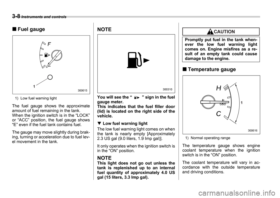
Fuel gauge
1) Low fuel warning light
The fuel gauge shows the approximate
amount of fuel remaining in the tank.
When the ignition switch is in the LOCK
or ACC position, the fuel gauge shows
E even if the fuel tank contains fuel.
The gauge may move slightly during brak-
ing, turning or acceleration due to fuel lev-
el movement in the tank.
NOTE
You will see the sign in the fuel
gauge meter.
This indicates that the fuel filler door
(lid) is located on the right side of the
vehicle.
Low fuel warning light
The low fuel warning light comes on when
the tank is nearly empty [Approximately
2.3 US gal (9.0 liters, 1.9 Imp gal)].
It only operates when the ignition switch is
in the ON position.
NOTE
This light does not go out unless the
tank is replenished up to an internal
fuel quantity of approximately 4.0 US
gal (15 liters, 3.3 Imp gal).
Temperature gauge
1) Normal operating range
The temperature gauge shows engine
coolant temperature when the ignition
switch is in the ON position.
The coolant temperature will vary in ac-
cordance with the outside temperature
and driving conditions.
1300615300310
Promptly put fuel in the tank when-
ever the low fuel warning light
comes on. Engine misfires as a re-
sult of an empty tank could cause
damage to the engine.
1
300616
Page 125 of 365
3-12 Instruments and controls
NOTE
If the connection between the combi-
nation meter and battery is broken for
any reason such as vehicle mainte-
nance or fuse replacement, the data re-
corded on the trip meter will be lost.
Tachometer
The tachometer shows the engine speed
in thousands of revolutions per minute.
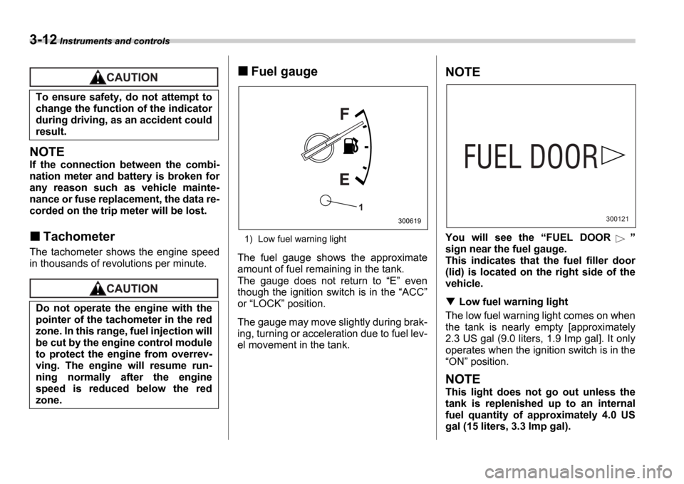
Fuel gauge
1) Low fuel warning light
The fuel gauge shows the approximate
amount of fuel remaining in the tank.
The gauge does not return to E even
though the ignition switch is in the ACC
or LOCK position.
The gauge may move slightly during brak-
ing, turning or acceleration due to fuel lev-
el movement in the tank.
NOTE
You will see the FUEL DOOR
sign near the fuel gauge.
This indicates that the fuel filler door
(lid) is located on the right side of the
vehicle.
Low fuel warning light
The low fuel warning light comes on when
the tank is nearly empty [approximately
2.3 US gal (9.0 liters, 1.9 Imp gal]. It only
operates when the ignition switch is in the ON position.
NOTE
This light does not go out unless the
tank is replenished up to an internal
fuel quantity of approximately 4.0 US
gal (15 liters, 3.3 Imp gal).
To ensure safety, do not attempt to
change the function of the indicator
during driving, as an accident could
result.
Do not operate the engine with the
pointer of the tachometer in the red
zone. In this range, fuel injection will
be cut by the engine control module
to protect the engine from overrev-
ving. The engine will resume run-
ning normally after the engine
speed is reduced below the red
zone.
1
300619300121
Page 126 of 365
Instruments and controls 3-13
Temperature gauge
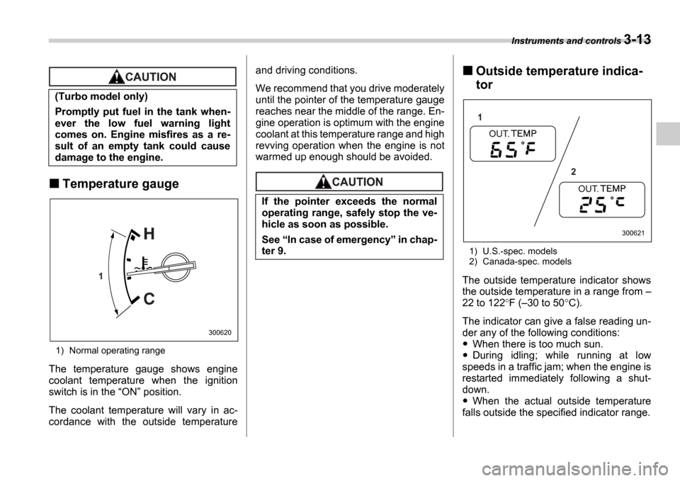
1) Normal operating range
The temperature gauge shows engine
coolant temperature when the ignition
switch is in the ON position.
The coolant temperature will vary in ac-
cordance with the outside temperature and driving conditions.
We recommend that you drive moderately
until the pointer of the temperature gauge
reaches near the middle of the range. En-
gine operation is optimum with the engine
coolant at this temperature range and high
revving operation when the engine is not
warmed up enough should be avoided.
Outside temperature indica-
tor
1) U.S.-spec. models
2) Canada-spec. models
The outside temperature indicator shows
the outside temperature in a range from
22 to 122 F ( 30 to 50 C).
The indicator can give a false reading un-
der any of the following conditions:
When there is too much sun.
During idling; while running at low
speeds in a traffic jam; when the engine is
restarted immediately following a shut-
down.
When the actual outside temperature
falls outside the specified indicator range.
(Turbo model only)
Promptly put fuel in the tank when-
ever the low fuel warning light
comes on. Engine misfires as a re-
sult of an empty tank could cause
damage to the engine.
1
300620
If the pointer exceeds the normal
operating range, safely stop the ve-
hicle as soon as possible.
See
In case of emergency in chap-
ter 9.
1
2
300621
Page 129 of 365
3-16 Instruments and controls
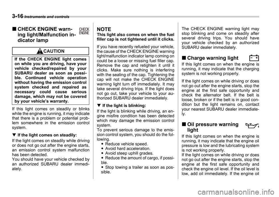
CHECK ENGINE warn-
ing light/Malfunction in-
dicator lamp
If this light comes on steadily or blinks
while the engine is running, it may indicate
that there is a problem or potential prob-
lem somewhere in the emission control
system.
If the light comes on steadily:
If the light comes on steadily while driving
or does not go out after the engine starts,
an emission control system malfunction
has been detected.
You should have your vehicle checked by
an authorized SUBARU dealer immedi-
ately.
NOTE
This light also comes on when the fuel
filler cap is not tightened until it clicks.
If you have recently refueled your vehicle,
the cause of the CHECK ENGINE warning
light/malfunction indicator lamp coming on
could be a loose or missing fuel filler cap.
Remove the cap and retighten it until it
clicks. Make sure nothing is interfering
with the sealing of the cap. Tightening the
cap will not make the CHECK ENGINE
warning light turn off immediately. It may
take several driving trips. If the light does
not go out, take your vehicle to your au-
thorized SUBARU dealer immediately.
If the light is blinking:
If the light is blinking while driving, an en-
gine misfire condition has been detected
which may damage the emission control
system.
To prevent serious damage to the emis-
sion control system, you should do the fol-
lowing.
Reduce vehicle speed.
Avoid hard acceleration.
Avoid steep uphill grades.
Reduce the amount of cargo, if possi-
ble.
Stop towing a trailer as soon as pos-
sible. The CHECK ENGINE warning light may
stop blinking and come on steadily after
several driving trips. You should have
your vehicle checked by an authorized
SUBARU dealer immediately.
Charge warning light
If this light comes on when the engine is
running, it may indicate that the charging
system is not working properly.
If the light comes on while driving or does
not go out after the engine starts, stop the
engine at the first safe opportunity and
check the alternator belt. If the belt is
loose, broken or if the belt is in good con-
dition but the light remains on, contact
your nearest SUBARU dealer immediate-
ly.
Oil pressure warning
light
If this light comes on when the engine is
running, it may indicate that the engine oil
pressure is low and the lubricating system
is not working properly.
If the light comes on while driving or does
not go out after the engine starts, stop the
engine at the first safe opportunity and
check the engine oil level. If the oil level is
low, add oil immediately. If the engine oil
If the CHECK ENGINE light comes
on while you are driving, have your
vehicle checked/repaired by your
SUBARU dealer as soon as possi-
ble. Continued vehicle operation
without having the emission control
system checked and repaired as
necessary could cause serious
damage, which may not be covered
by your vehicle
s warranty.
Page 139 of 365
3-26 Instruments and controls
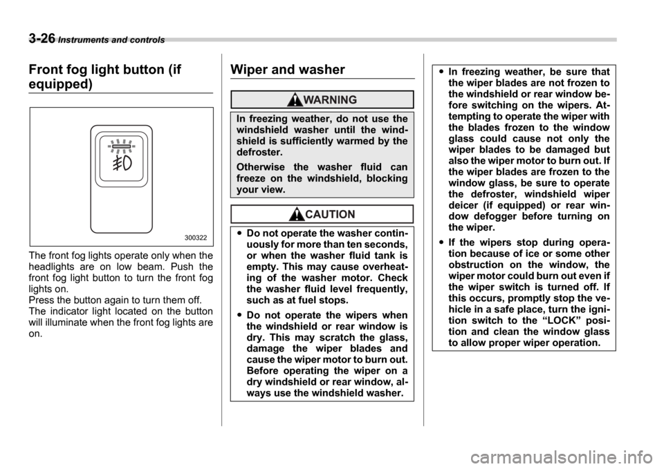
Front fog light button (if
equipped)
The front fog lights operate only when the
headlights are on low beam. Push the
front fog light button to turn the front fog
lights on.
Press the button again to turn them off.
The indicator light located on the button
will illuminate when the front fog lights are
on.
Wiper and washer
300322
In freezing weather, do not use the
windshield washer until the wind-
shield is sufficiently warmed by the
defroster.
Otherwise the washer fluid can
freeze on the windshield, blocking
your view.
Do not operate the washer contin-
uously for more than ten seconds,
or when the washer fluid tank is
empty. This may cause overheat-
ing of the washer motor. Check
the washer fluid level frequently,
such as at fuel stops.
Do not operate the wipers when
the windshield or rear window is
dry. This may scratch the glass,
damage the wiper blades and
cause the wiper motor to burn out.
Before operating the wiper on a
dry windshield or rear window, al-
ways use the windshield washer.
In freezing weather, be sure that
the wiper blades are not frozen to
the windshield or rear window be-
fore switching on the wipers. At-
tempting to operate the wiper with
the blades frozen to the window
glass could cause not only the
wiper blades to be damaged but
also the wiper motor to burn out. If
the wiper blades are frozen to the
window glass, be sure to operate
the defroster, windshield wiper
deicer (if equipped) or rear win-
dow defogger before turning on
the wiper.
If the wipers stop during opera-
tion because of ice or some other
obstruction on the window, the
wiper motor could burn out even if
the wiper switch is turned off. If
this occurs, promptly stop the ve-
hicle in a safe place, turn the igni-
tion switch to the LOCK posi-
tion and clean the window glass
to allow proper wiper operation.
Page 194 of 365
Interior equipment 6-9
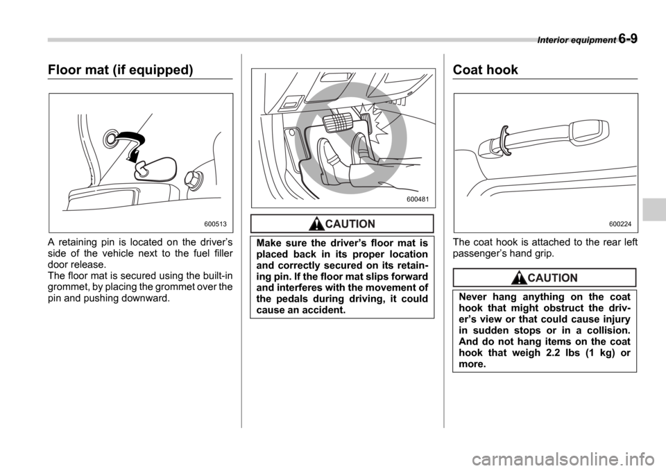
Floor mat (if equipped)
A retaining pin is located on the driver s
side of the vehicle next to the fuel filler
door release.
The floor mat is secured using the built-in
grommet, by placing the grommet over the
pin and pushing downward.
Coat hook
The coat hook is attached to the rear left
passenger s hand grip.
600513
Make sure the driver s floor mat is
placed back in its proper location
and correctly secured on its retain-
ing pin. If the floor mat slips forward
and interferes with the movement of
the pedals during driving, it could
cause an accident.
600481
Never hang anything on the coat
hook that might obstruct the driv-
er s view or that could cause injury
in sudden stops or in a collision.
And do not hang items on the coat
hook that weigh 2.2 lbs (1 kg) or
more.
600224