2006 SUBARU IMPREZA check engine
[x] Cancel search: check enginePage 150 of 365

4
Climate control
Ventilator ............................................................. 4-2
Air flow selection ................................ .................... 4-2
Center and side ventilators ....................... ............. 4-3
Manual climate control system (if equipped) ..................................... ............... 4-3
Control panel ..................................... ..................... 4-3
Heater operation .................................. ................... 4-5
Air conditioner operation (if equipped) ........... ..... 4-7
Automatic climate control system (if equipped) ..................................... ............... 4-7
Control panel ..................................... ..................... 4-8
To use as full-automatic climate control
system ............................................ ....................... 4-8
To use as semi-automatic climate control system ............................................ ....................... 4-8
Fan speed control dial ............................ ............... 4-8
Temperature control dial .......................... .............. 4-9
Air flow control dial ............................. ................... 4-9
Air inlet selection button ........................ ................ 4-9
Air conditioner button ............................ ................ 4-10
Temperature sensors ............................... .............. 4-10
Operating tips for heater and air conditioner ....................................... ............... 4-11
Cleaning ventilation grille ....................... ............... 4-11
Efficient cooling after parking in direct sunlight .......................................... ....................... 4-11
Lubrication oil circulation in the refrigerant
circuit ........................................... ......................... 4-11Checking air conditioning system before
summer season ..................................... ............... 4-11
Cooling and dehumidifying in high humidity and
low temperature weather conditions ................ .. 4-11
Air conditioner compressor shut-off when engine is heavily loaded .......................... ............ 4-12
Refrigerant for your climate control system ....... . 4-12
Air filtration system ............................. ............... 4-12
Replacing an air filter ........................... .................. 4-12
Page 160 of 365
Climate control 4-11
CONTINUED
Do not subject the sensors to impact.
Keep water away from the sensors.
Do not cover the sensors.
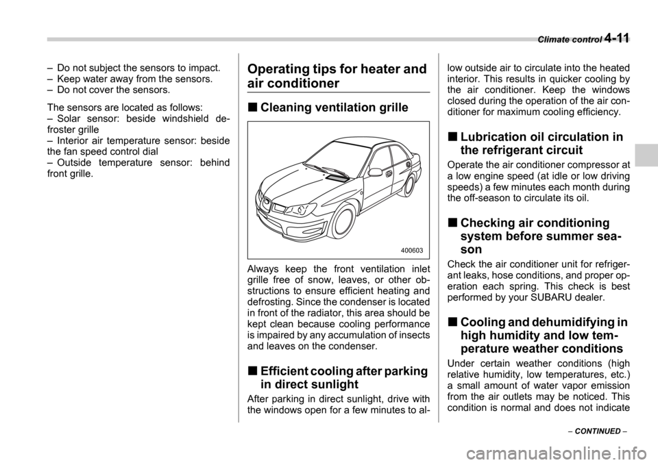
The sensors are located as follows: Solar sensor: beside windshield de-
froster grille Interior air temperature sensor: beside
the fan speed control dial Outside temperature sensor: behind
front grille.
Operating tips for heater and
air conditioner
Cleaning ventilation grille
Always keep the front ventilation inlet
grille free of snow, leaves, or other ob-
structions to ensure efficient heating and
defrosting. Since the condenser is located
in front of the radiator, this area should be
kept clean because cooling performance
is impaired by any accumulation of insects
and leaves on the condenser.
Efficient cooling after parking
in direct sunlight
After parking in direct sunlight, drive with
the windows open for a few minutes to al- low outside air to circulate into the heated
interior. This results in quicker cooling by
the air conditioner. Keep the windows
closed during the operation of the air con-
ditioner for maximum cooling efficiency.
Lubrication oil circulation in
the refrigerant circuit
Operate the air conditioner compressor at
a low engine speed (at idle or low driving
speeds) a few minutes each month during
the off-season to circulate its oil.
Checking air conditioning
system before summer sea-
son
Check the air conditioner unit for refriger-
ant leaks, hose conditions, and proper op-
eration each spring. This check is best
performed by your SUBARU dealer.
Cooling and dehumidifying in
high humidity and low tem-
perature weather conditions
Under certain weather conditions (high
relative humidity, low temperatures, etc.)
a small amount of water vapor emission
from the air outlets may be noticed. This
condition is normal and does not indicate
400603
Page 161 of 365
4-12 Climate control
any problem with the air conditioning sys-
tem.
Air conditioner compressor
shut-off when engine is
heavily loaded
To improve acceleration and gas mileage,
the air conditioner compressor is de-
signed to temporarily shut off during air
conditioner operation whenever the accel-
erator is fully depressed such as during
rapid acceleration or when driving on a
steep upgrade.
Refrigerant for your climate
control system
Your air conditioner uses ozone friendly
refrigerant HFC134a. Therefore, the
method of adding, changing or checking
the refrigerant is different from the method
for CFC12 (Freon). Consult your
SUBARU dealer for service. Repairs
needed as a result of using the wrong re-
frigerant are not covered under warranty.
Air filtration system
If your vehicle s air conditioning system is
equipped with an air filtration system, re-
place the filter element according to the
replacement schedule shown in the fol-
lowing. This schedule should be followed
to maintain the filter s dust collection abili-
ty. Under extremely dusty conditions, the
filter should be replaced more frequently.
It is recommended that you have your fil-
ter checked or replaced by your SUBARU
dealer. For replacement, use only a genu-
ine SUBARU air filter kit.
Replacement schedule:
Every 12 months or 7,500 miles (12,000
km) whichever comes first
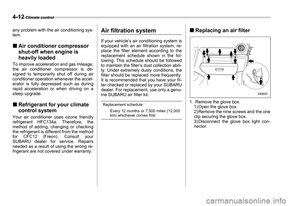
Replacing an air filter
1. Remove the glove box.1) Open the glove box.
2) Remove the nine screws and the one
clip securing the glove box.
3) Disconnect the glove box light con-
nector.
400604
Page 198 of 365

7
Starting and operating
Fuel ...................................................................... 7-2
Fuel requirements ................................. ................. 7-2
Fuel filler lid and cap ........................... ................... 7-4
State emission testing (U.S. only) ................ .... 7-5
Preparing to drive ................................ .............. 7-6
Starting the engine ............................... .............. 7-7
Manual transmission vehicle ....................... .......... 7-7
Automatic transmission vehicle .................... ........ 7-7
Stopping the engine ............................... ............ 7-8
Manual transmission 6 speeds (WRX-STI) ... 7-9
Selecting reverse gear ............................ ............... 7-9
Shifting speeds ................................... .................... 7-9
Driving tips ...................................... ........................ 7-10
Manual transmission 5 speeds (except
WRX-STI) .......................................... ................ 7-11
Shifting speeds ................................... .................... 7-11
Driving tips ...................................... ........................ 7-12
Driver s Control Center Differential (DCCD)
(WRX-STI) ......................................... ............... 7-12
Auto mode ......................................... ...................... 7-13
Manual mode ....................................... .................... 7-13
Temporary release ................................. ................. 7-15
Automatic transmission ............................ ........ 7-16
Selector lever for automatic transmission ......... .. 7-16
Shift lock release ................................ .................... 7-19
Limited slip differential (LSD) (if equipped) ..... 7-20
Power steering .................................... ............... 7-21Braking ...........................................
..................... 7-21
Braking tips ...................................... ....................... 7-21
Brake system ...................................... .................... 7-21
Disc brake pad wear warning indicators ............ .. 7-22
ABS (Anti-lock Brake System) ...................... .... 7-22
ABS system self-check ............................. ............. 7-22
ABS warning light ................................. .................. 7-23
Electronic Brake Force Distribution (EBD) system ............................................ .................. 7-24
Steps to take if EBD system fails ................. ......... 7-24
Parking your vehicle .............................. ............ 7-25
Parking brake ..................................... ..................... 7-25
Parking tips ...................................... ....................... 7-25
Cruise control .................................... ................. 7-27
To set cruise control ............................. ................. 7-27
To temporarily cancel the cruise control .......... ... 7-28
To turn off the cruise control .................... ............. 7-28
To change the cruising speed ...................... ......... 7-28
Page 200 of 365
Starting and operating 7-3
CONTINUED
problem is fuel related before returning
your vehicle to an authorized dealer for
service.
MMT
Some gasoline contains an octane-en-
hancing additive called MMT (Methylcy-
clopentadienyl Manganese Tricarbonyl). If
you use such fuels, your emission control
system performance may deteriorate and
the CHECK ENGINE warning light/Mal-
function indicator lamp may turn on. If this
happens, return to your authorized
SUBARU Dealer for service. If it is deter-
mined that the condition is caused by the
type of fuel used, repairs may not be cov-
ered by your warranty.
Gasoline for cleaner air
Your use of gasoline with detergent addi-
tives will help prevent deposits from form-
ing in your engine and fuel system. This
helps keep your engine in tune and your
emission control system working properly,
and is a way of doing your part for cleaner
air. If you continuously use a high quality
fuel with the proper detergent and other
additives, you should never need to add
any fuel system cleaning agents to your
fuel tank.
Many gasolines are now blended with ma-
terials called oxygenates. Use of these fu- els can also help keep the air cleaner. Ox-
ygenated blend fuels, such as MTBE (Me-
thyl Tertiary Butyl ether) or ethanol (ethyl
or grain alcohol) may be used in your ve-
hicle, but should contain no more than
15% MTBE or 10% ethanol for the proper
operation of your SUBARU.
In addition, some gasoline suppliers are
now producing reformulated gasolines,
which are designed to reduce vehicle
emissions. SUBARU approves the use of
reformulated gasoline.
If you are not sure what the fuel contains,
you should ask your service station oper-
ators if their gasolines contain detergents
and oxygenates and if they have been re-
formulated to reduce vehicle emissions.
As additional guidance, only use fuels
suited for your vehicle as explained in the
following.
Fuel should be unleaded and have an
octane rating no lower than that specified
in this manual.
Methanol (methyl or wood alcohol) is
sometimes mixed with unleaded gasoline.
Methanol can be used in your vehicle
ONLY if it does not exceed 5% of the fuel
mixture AND if it is accompanied by suffi-
cient quantities of the proper cosolvents
and corrosion inhibitors required to pre- vent damage to the fuel system. Do not
use fuel containing methanol
EXCEPT un-
der these conditions.
If undesirable driveability problems are
experienced and you suspect they may be
fuel related, try a different brand of gaso-
line before seeking service at your
SUBARU dealer.
Fuel system damage or driveability
problems which result from the use of im-
proper fuel are not covered under the
SUBARU Limited Warranty.
Do not let fuel spill on the exterior
surfaces of the vehicle. Fuels con-
taining alcohol may cause paint
damage, which is not covered under
the SUBARU Limited Warranty.
Page 201 of 365
7-4 Starting and operating
Fuel filler lid and cap
Refueling0
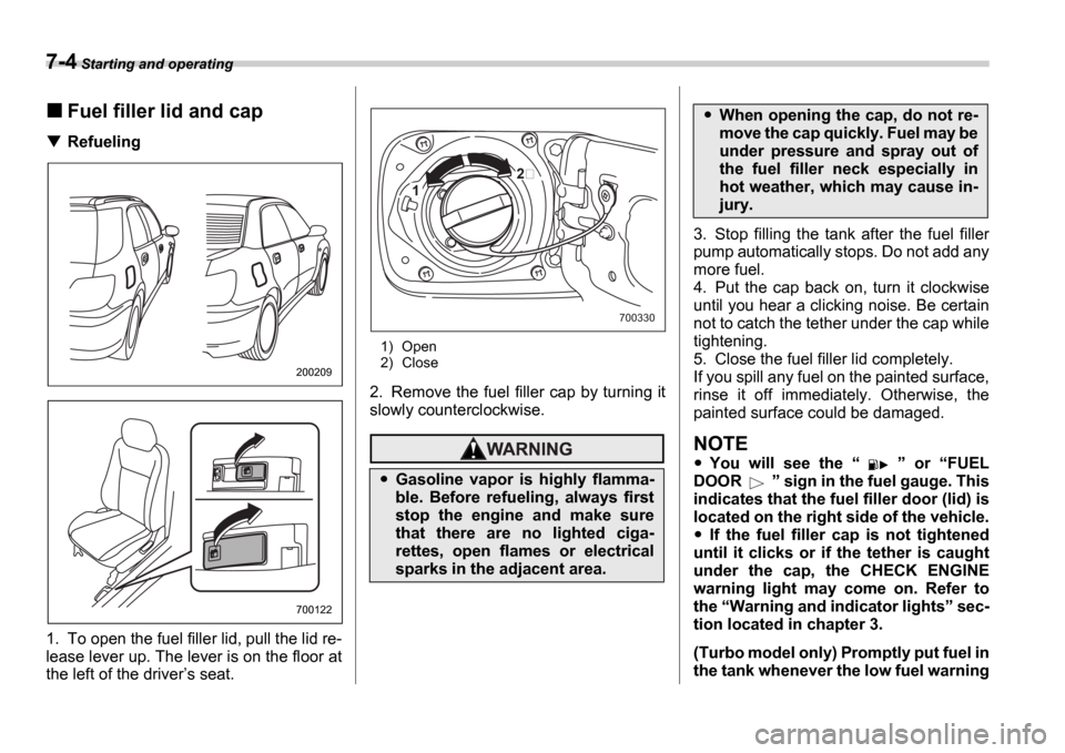
1. To open the fuel filler lid, pull the lid re-
lease lever up. The lever is on the floor at
the left of the driver s seat.
1) Open
2) Close
2. Remove the fuel filler cap by turning it
slowly counterclockwise.
3. Stop filling the tank after the fuel filler
pump automatically stops. Do not add any
more fuel.
4. Put the cap back on, turn it clockwise
until you hear a clicking noise. Be certain
not to catch the tether under the cap while
tightening.
5. Close the fuel filler lid completely.
If you spill any fuel on the painted surface,
rinse it off immediately. Otherwise, the
painted surface could be damaged.
NOTE
You will see the or FUEL
DOOR sign in the fuel gauge. This
indicates that the fuel filler door (lid) is
located on the right side of the vehicle.
If the fuel filler cap is not tightened
until it clicks or if the tether is caught
under the cap, the CHECK ENGINE
warning light may come on. Refer to
the Warning and indicator lights sec-
tion located in chapter 3.
(Turbo model only) Promptly put fuel in
the tank whenever the low fuel warning
200209
700122
Gasoline vapor is highly flamma-
ble. Before refueling, always first
stop the engine and make sure
that there are no lighted ciga-
rettes, open flames or electrical
sparks in the adjacent area.
1
700330
When opening the cap, do not re-
move the cap quickly. Fuel may be
under pressure and spray out of
the fuel filler neck especially in
hot weather, which may cause in-
jury.
Page 203 of 365
7-6 Starting and operating
The EPA has issued regulations for in-
specting the On-Board Diagnostic (OBD)
system as part of the state emissions in-
spection. The OBD system is designed to
detect engine and transmission problems
that might cause vehicle emissions to ex-
ceed allowable limits. These inspections
apply to all 1996 model year and newer
passenger cars and light trucks. Over 30
states plus the District of Columbia have
implemented the OBD system inspection.
The inspection of the OBD system con-
sists of a visual operational check of the CHECK ENGINE warning light/malfunc-
tion indicator lamp (MIL) and an examina-
tion of the OBD system with an electronic
scan tool while the engine is running.
A vehicle passes the OBD system in-
spection if proper the CHECK ENGINE
warning light/MIL illumination is observed,
there is no stored diagnostic trouble
codes, and the OBD system readiness
monitors are complete.
A vehicle fails the OBD inspection if the
CHECK ENGINE warning light/MIL is
not properly operating or there is one or
more diagnostic trouble codes stored in
vehicle s computer with the CHECK EN-
GINE warning light/MIL illuminated.
A state emission inspection may reject
(not pass or fail) a vehicle if the number of
OBD system readiness monitors Not
Ready is greater than one. Under this
condition, the vehicle operator should be
instructed to drive his/her vehicle for a few
days to set the monitors and return for an
emission re-inspection.
Owners of rejected or failing vehicles
should contact their Subaru Dealer for
service.
Preparing to drive
You should perform the following checks
and adjustments every day before you
start driving.
1. Check that all windows, mirrors, and
lights are clean and unobstructed.
2. Check the appearance and condition of
the tires. Also check tires for proper infla-
tion.
3. Look under the vehicle for any sign of
leaks.
4. Check that the hood, trunk (Sedan)
and rear gate (Wagon) are fully closed.
5. Check the adjustment of the seat.
6. Check the adjustment of the inside and
outside mirrors.
7. Fasten your seatbelt. Check that your
passengers have fastened their seatbelts.
8. Check the operation of the warning and
indicator lights when the ignition switch is
turned to the ON position.
9. Check the gauges, indicator and warn-
ing lights after starting the engine.
NOTE
Engine oil, engine coolant, brake fluid,
washer fluid and other fluid levels
should be checked daily, weekly or at
fuel stops.
Resultant vehicle damage due to im-
proper testing is not covered under
the SUBARU Limited Warranty and
is the responsibility of the state in-
spection program or its contractors
or licensees.
Page 204 of 365
Starting and operating 7-7
CONTINUED
Starting the engine
Manual transmission vehicle
1. Apply the parking brake.
2. Turn off unnecessary lights and acces-
sories.
3. Press the clutch pedal to the floor and
shift the shift lever into neutral. Hold the
clutch pedal to the floor while starting the
engine.
The starter motor will only operate when
the clutch pedal is pressed fully to the
floor.
4. Turn the ignition switch to the ON po-
sition and check the operation of the warn-
ing and indicator lights. Refer to the Warning and indicator lights section
(chapter 3).
5. Turn the ignition switch to the START
position without depressing the accelera-
tor pedal. Release the key immediately af-
ter the engine has started. If the engine does not start, try the follow-
ing.
1) Turn the ignition switch to the OFF
position and wait for at least 10 sec-
onds. After checking that the parking
brake is firmly set, turn the ignition
switch to the START position while de-
pressing the accelerator pedal slightly
(approximately a quarter of the full
stroke). Release the accelerator pedal
as soon as the engine starts.
2) If this fails to start the engine, turn the
ignition switch back to the OFF posi-
tion and wait for at least 10 seconds.
Then fully depress the accelerator ped-
al and turn the ignition switch to the START position. If the engine starts,
quickly release the accelerator pedal.
3) If this fails to start the engine, turn the
ignition switch again to the OFF posi-
tion. After waiting for 10 seconds or
longer, turn the ignition switch to the START position without depressing
the accelerator pedal.
4) If the engine still refuses to start, con-
tact your nearest SUBARU dealer for
assistance.
6. Confirm that all warning and indicator
lights have gone off after the engine has
started. The fuel injection system auto-
matically lowers the idle speed as the en-
gine warms up.
NOTE
The engine may be difficult to start
when the battery has been disconnect-
ed and reconnected (for maintenance
or other purposes). This difficulty is
caused by the electronically controlled
throttle s self-diagnosis function. To
overcome it, keep the ignition switch in
the ON position for approximately 10
seconds before starting the engine.
Automatic transmission vehi-
cle
1. Apply the parking brake.
2. Turn off unnecessary lights and acces-
sories.
3. Shift the selector lever to the P or N
position (preferably P position).
The starter motor will only operate when
the select lever is at the P or N position.
4. Turn the ignition switch to the ON po-
sition and check the operation of the warn-
ing and indicator lights. Refer to the Warning and indicator lights section
(chapter 3).
5. Turn the ignition switch to the START
position without depressing the accelera-
tor pedal. Release the key immediately af-
ter the engine has started.
If the engine does not start, try the follow-
Do not operate the starter motor
continuously for more than ten sec-
onds. If the engine fails to start after
operating the starter for five to ten
seconds, wait for ten seconds or
more before trying again.