Page 338 of 444

0-20
RODIUS 2007.07
4892-01
ABS SYSTEM
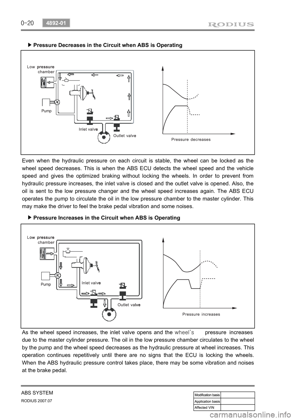
Pressure Decreases in the Circuit when ABS is Operating ▶
Pressure Increases in the Circuit when ABS is Operating ▶
Even when the hydraulic pressure on each circuit is stable, the wheel can be locked as the
wheel speed decreases. This is when the ABS ECU detects the wheel speed and the vehicle
speed and gives the optimized braking without locking the wheels. In order to prevent from
hydraulic pressure increases, the inlet valve is closed and the outlet valve is opened. Also, the
oil is sent to the low pressure changer and the wheel speed increases again. The ABS ECU
operates the pump to circulate the oil in the low pressure chamber to the master cylinder. This
may make the driver to feel the brake pedal vibration and some noises.
As the wheel speed increases, the inlet valve opens and the wheel’s pressure increases
due to the master cylinder pressure. The oil in the low pressure chamber circulates to the wheel
by the pump and the wheel speed decreases as the hydraulic pressure at wheel increases. This
operation continues repetitively until there are no signs that the ECU is locking the wheels.
When the ABS hydraulic pressure control takes place, there may be some vibration and noises
at the brake pedal.
Page 339 of 444
0-21
ABS SYSTEM
RODIUS 2007.07
4892-01
(3) COMPONENTS DESCRIPTION
HECU (Hydraulic & Electronic Control Unit) ▶
Motor Pump ▶
Valve Body ▶
HECU consists of motor pump (1), solenoid
valve (2) and ECU (3).
ECU connector has 47 pins and the numbe
r
of valves in valve body is 6 when equipped
with only ABS and 12 when equipped with
ESP system.
The motor is operated when ABS is
activated. The cam-shaped output shaft o
f
the motor enables the brake system to
receive and supply the brake fluid during the
motor operation.
The cam bushing is installed between
plungers and it draws and discharges the
brake fluid.
Page 340 of 444
0-22
RODIUS 2007.07
4892-01
ABS SYSTEM
Pumping
▶
ECU (Including Solenoid Valves ? ESP Equipped Model)
▶
ECU lower cover)
▶
When the cam pushes the left plunger
during motor operation, the system pressure
is generated in the left cylinder. At this time,
the right plunger is expanded by spring force
and the expanded volume of the right
cylinder draws the brake fluid.
HECU controls the hydraulic valves by
supplying or cutting off the voltage to
solenoid valves depending on the wheel
speed and other information from wheel
speed sensors.
The figure shown in left side is for ESP
ECU. There are two channels for front
wheels and one channel for rear wheels.
Each channel has one inlet and one outlet
valve, therefore,
there are six solenoid valves.
The electrical components are weak to
moisture. To protect ECU, GoreTex-based
plate is used at ECU lower cover. The vent
hall (arrow) allows air to ventilate but does
not allow moisture to penetrate.
Page 352 of 444

0-8
RODIUS 2007.07
4710-09
WHEEL
3. WHEEL ALIGNMENT
The first responsibility of engineering is to design safe steering and suspension systems. Each
component must be strong enough to with stand and absorb extreme punishment.
Both the steering system and the front and the rear suspension must function geometrically
with the body mass.
The steering and suspension systems require that the front wheels self-return and that the tire
rolling effort and the road friction be held to a negligible force in order to allow the customer to
direct the vehicle with the least effort and the most comfort.
A complete wheel alignment check should include measurements of the rear toe and camber.
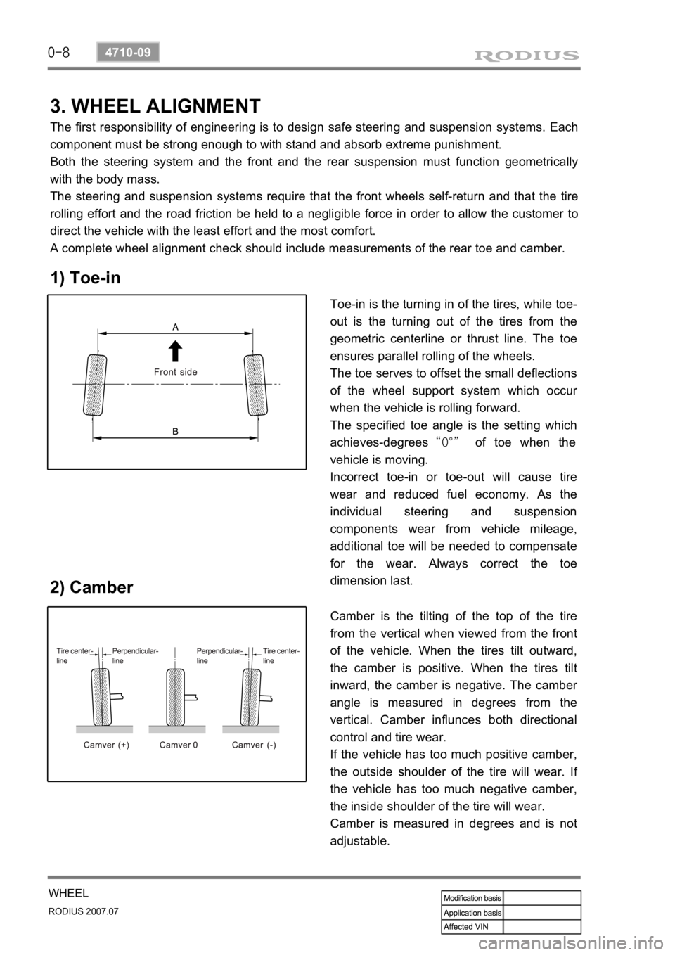
1) Toe-in
2) Camber
Toe-in is the turning in of the tires, while toe-
out is the turning out of the tires from the
geometric centerline or thrust line. The toe
ensures parallel rolling of the wheels.
The toe serves to offset the small deflections
of the wheel support system which occu
r
when the vehicle is rolling forward.
The specified toe angle is the setting which
achieves-degrees “0°” of toe when the
vehicle is moving.
Incorrect toe-in or toe-out will cause tire
wear and reduced fuel economy. As the
individual steering and suspension
components wear from vehicle mileage,
additional toe will be needed to compensate
for the wear. Always correct the toe
dimension last.
Camber is the tilting of the top of the tire
from the vertical when viewed from the front
of the vehicle. When the tires tilt outward,
the camber is positive. When the tires tilt
inward, the camber is negative. The cambe
r
angle is measured in degrees from the
vertical. Camber influnces both directional
control and tire wear.
If the vehicle has too much positive camber,
the outside shoulder of the tire will wear. I
f
the vehicle has too much negative camber,
the inside shoulder of the tire will wear.
Camber is measured in degrees and is not
adjustable.
Page 385 of 444

0-6
RODIUS 2007.07
8810-01
AIR BAG SYSTEM
3. AIRBAG FUNCTION DESCRIPTION
1) Bag (Cushion)
The airbag system performance is influenced on the cushion size, shape and position.
The cushion strength is a important parameter on the impact absorb effect.
Therefore, the control of the airbag performance depends on cushion size, shape, inflato
r
characteristic and vent hole size for the gas discharge.
The cushion’s material and folding function to control the cushion deployment
direction and the performance to protect passenger’s face. ·
·
·
·
2) Airbag Module
The driver airbag module is under the center pad of the steering wheel.
The passenger airbag module is installed in the instrument panel at passenger side.
The driver and passenger side airbag is inside each seat.
3) Module Cover/Housing
It is a type of a container that includes the cushion and the inflator.
The module housing functions to deliver the reaction force between the body structure and
the airbag (The airbag reaction is absorbed generally to the steering wheel or instrument
panel).
The module cover must be considered in a viewpoint of protection between exterior,
internal units and cushion. Also the module cover should be designed not to cause any
personal injury for deployment. ·
·
·
Do not disassemble the airbag module because unintentional deployment of the airbags
resulting from any damage or interference of the module can cause injury. -
Page 435 of 444
06-16
RODIUS 2007.07
7115-01
BODY EXTERIOR
Shock absorber
Door latch
Door hinge
Door striker