Page 288 of 444
0-33310-01
1. PROPELLER SHAFT GENERAL INFORMATION
The propeller shaft transfers the power through the
transmission and transfer case to the front/rear axle
differential carrier (final reduction gear). It is
manufactured by a thin rounded steel pipe to have
the strong resisting force against the torsion and
bending. Both ends of propeller shaft are connected
to the spider and the center of propeller shaft is
connected to the spline to accommodate the
changes of the height and length. The rubbe
r
bushing that covers the intermediate bearing keeps
the balance of rear propeller shaft and absorbs its
vibration.
2. SPECIFICATION
Page 292 of 444
0-5
SUSPENSION SYSTEM
RODIUS 2007.07
4111-01
3. STRUCTURE OF SHOCK ABSORBER AND COIL SPRING
1) front coil spring
▶ Specification
Page 293 of 444
0-6
RODIUS 2007.07
4111-01
SUSPENSION SYSTEM
2) front shock absorber assembly
▶ Specification
Page 294 of 444
0-7
SUSPENSION SYSTEM
RODIUS 2007.07
4111-01
Marking Point
3) rear shock absorber
Keep the suitable distance when compressed and expanded.
Minimum length is 10 mm longer than the minimum length under compression. ·
·
▶Specification
Page 301 of 444
0-8
RODIUS 2007.07
4830-01
BRAKS SYSTEM
6) Master Cylider & Booster
ABS system is basically equipped to STAVIC.
Vehicle which adapted ESP system in option has two pressure sensors under master cylinder
and these two sensor are used for BAS (Brake Assist System) system.
Do not disassemble the brake oil pressure sensors These can not be reinstalled of
disassembled.
After reinstall the reserver tank perform a air bleeding of brake system
-
-
Vehicle with ESP Vehicle with ABS
Brake fluid reservoir tank Master cylinder
Page 302 of 444
0-3
ESP SYSTEM
RODIUS 2007.07
4892-01
8510-56ABS/ESP System
1. SPECCIFICATIONS OF ESP SYSTEM
1) Specifications Of Pressure Sensor
2) Specifications Of Sensor Cluster
(sensor cluster: yaw rate sensor + lateral acceleration sensor + Longitudinal acceleration sensor)
3) Specifications Of Wheel Speed Sensor
4) Specifications Of Steering Wheel Angle sensor
Page 306 of 444

0-7
ESP SYSTEM
RODIUS 2007.07
4892-01
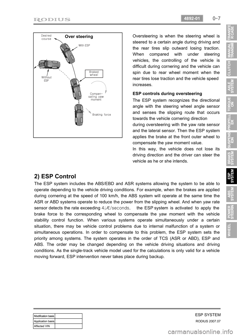
Over steeringOversteering is when the steering wheel is
steered to a certain angle during driving and
the rear tires slip outward losing traction.
When compared with under steering
vehicles, the controlling of the vehicle is
difficult during cornering and the vehicle can
spin due to rear wheel moment when the
rear tires lose traction and the vehicle speed
increases.
ESP controls during oversteering
The ESP system recognizes the directional
angle with the steering wheel angle senso
r
and senses the slipping route that occurs
towards the vehicle cornering direction
during oversteering with the yaw rate senso
r
and the lateral sensor. Then the ESP system
applies the brake at the front outer wheel to
compensate the yaw moment value.
In this way, the vehicle does not lose its
driving direction and the driver can steer the
vehicle as he or she intends.
2) ESP Control
The ESP system includes the ABS/EBD and ASR systems allowing the system to be able to
operate depending to the vehicle driving conditions. For example, when the brakes are applied
during cornering at the speed of 100 km/h, the ABS system will operate at the same time the
ASR or ABD systems operate to reduce the power from the slipping wheel. And when yaw rate
sensor detects the rate exceeding 4¡Æ/seconds, the ESP system is activated to apply the
brake force to the corresponding wheel to compensate the yaw moment with the vehicle
stability control function. When various systems operate simultaneously under a certain
situation, there may be vehicle control problems due to internal malfunction of a system o
r
simultaneous operations. In order to compensate to this problem, the ESP system sets the
priority among systems. The system operates in the order of TCS (ASR or ABD), ESP and
ABS. The order may be changed depending on the vehicle driving situations and driving
conditions. As the single-track vehicle model used for the calculations is only valid for a vehicle
moving forward, ESP intervention never takes place during backup.
Page 307 of 444

0-8
RODIUS 2007.07
4892-01
ESP SYSTEM
2) ESP Control
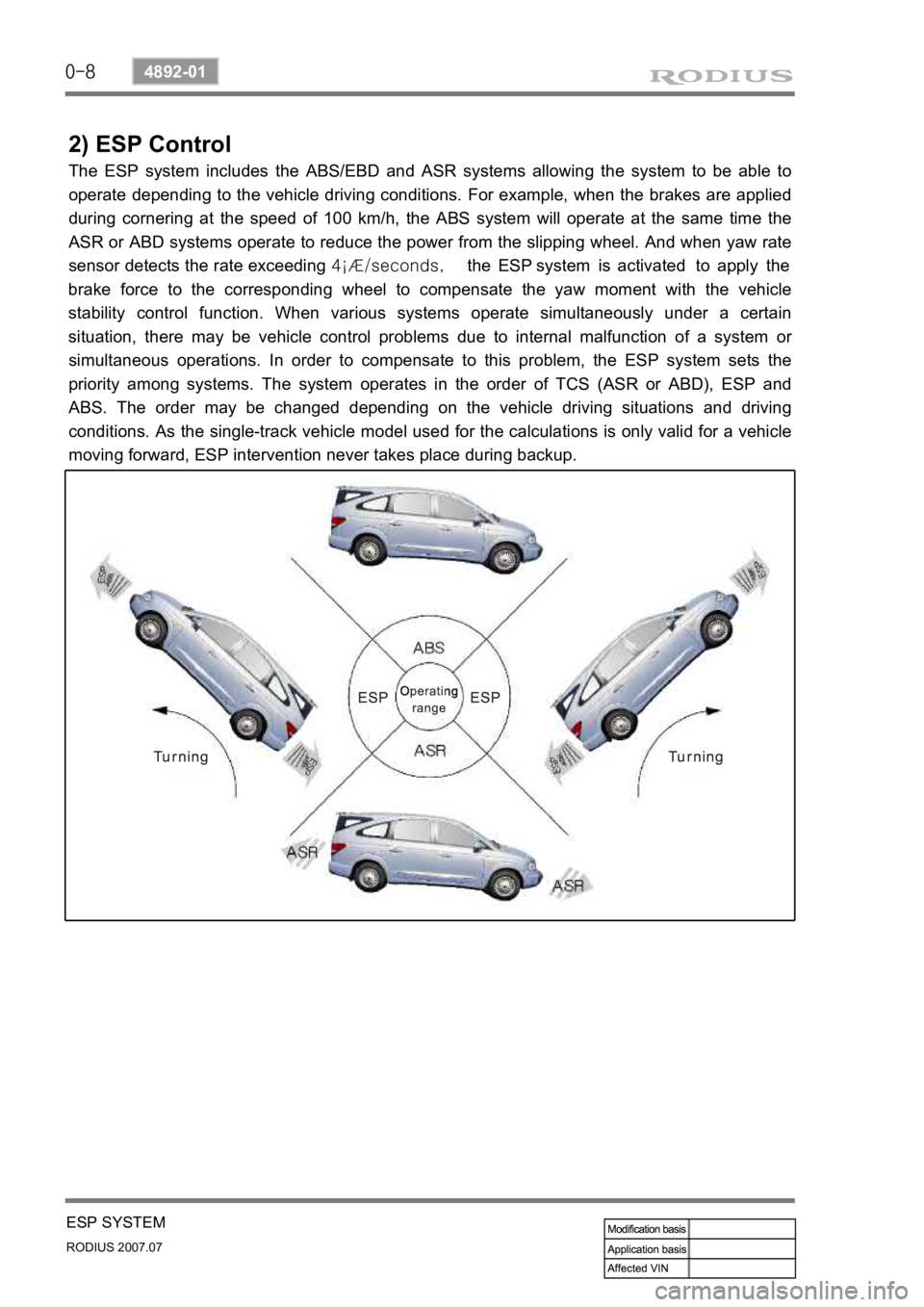
The ESP system includes the ABS/EBD and ASR systems allowing the system to be able to
operate depending to the vehicle driving conditions. For example, when the brakes are applied
during cornering at the speed of 100 km/h, the ABS system will operate at the same time the
ASR or ABD systems operate to reduce the power from the slipping wheel. And when yaw rate
sensor detects the rate exceeding 4¡Æ/seconds, the ESP system is activated to apply the
brake force to the corresponding wheel to compensate the yaw moment with the vehicle
stability control function. When various systems operate simultaneously under a certain
situation, there may be vehicle control problems due to internal malfunction of a system o
r
simultaneous operations. In order to compensate to this problem, the ESP system sets the
priority among systems. The system operates in the order of TCS (ASR or ABD), ESP and
ABS. The order may be changed depending on the vehicle driving situations and driving
conditions. As the single-track vehicle model used for the calculations is only valid for a vehicle
moving forward, ESP intervention never takes place during backup.