Page 2419 of 2896

PRECAUTIONS
MTC-7
C
D
E
F
G
H
I
K
L
MA
B
MTC
Revision: June 20062007 Versa
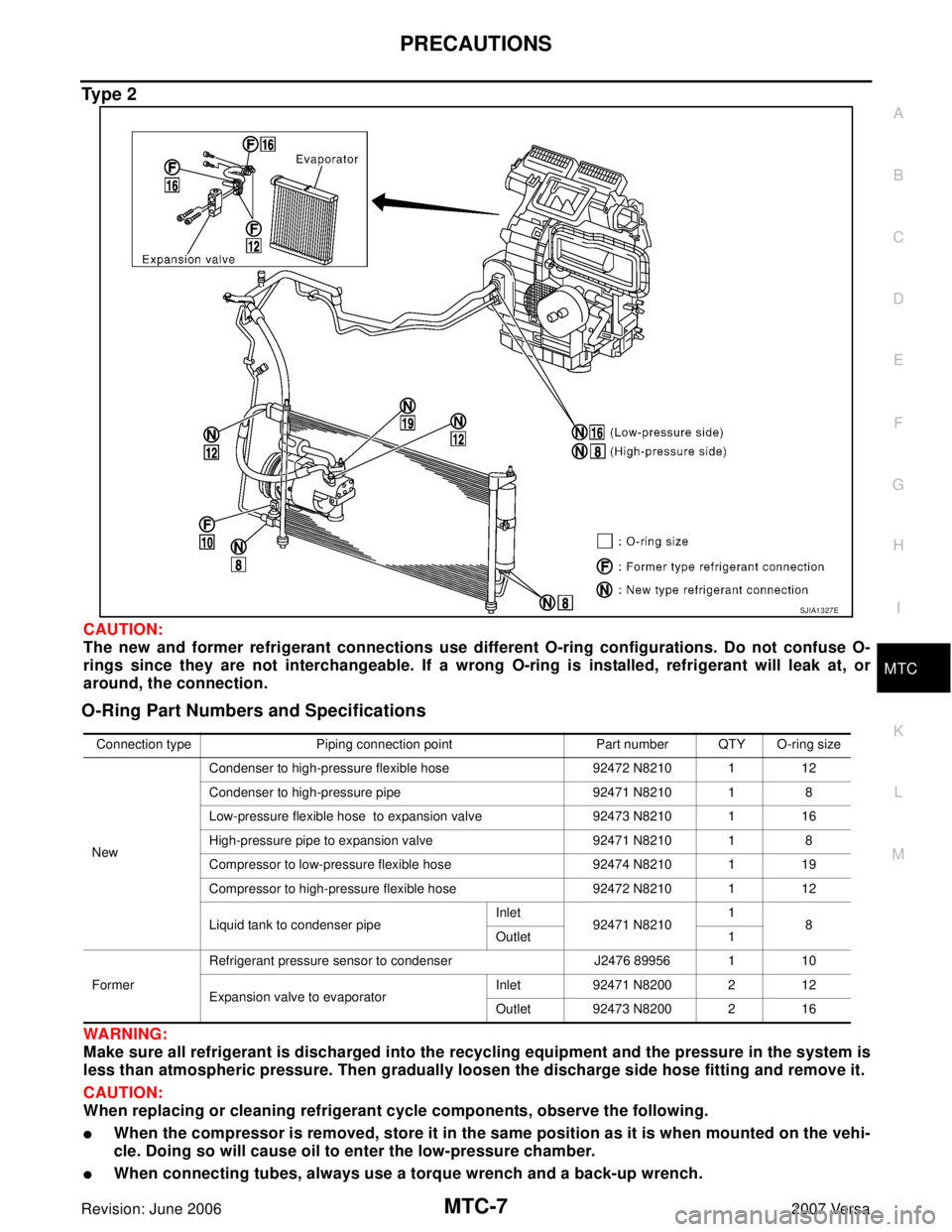
Ty p e 2
CAUTION:
The new and former refrigerant connections use different O-ring configurations. Do not confuse O-
rings since they are not interchangeable. If a wrong O-ring is installed, refrigerant will leak at, or
around, the connection.
O-Ring Part Numbers and Specifications
WA RN ING:
Make sure all refrigerant is discharged into the recycling equipment and the pressure in the system is
less than atmospheric pressure. Then gradually loosen the discharge side hose fitting and remove it.
CAUTION:
When replacing or cleaning refrigerant cycle components, observe the following.
�When the compressor is removed, store it in the same position as it is when mounted on the vehi-
cle. Doing so will cause oil to enter the low-pressure chamber.
�When connecting tubes, always use a torque wrench and a back-up wrench.
SJIA1327E
Connection type Piping connection point Part number QTY O-ring size
NewCondenser to high-pressure flexible hose 92472 N8210 1 12
Condenser to high-pressure pipe 92471 N8210 1 8
Low-pressure flexible hose to expansion valve 92473 N8210 1 16
High-pressure pipe to expansion valve 92471 N8210 1 8
Compressor to low-pressure flexible hose 92474 N8210 1 19
Compressor to high-pressure flexible hose 92472 N8210 1 12
Liquid tank to condenser pipeInlet
92471 N82101
8
Outlet 1
FormerRefrigerant pressure sensor to condenser J2476 89956 1 10
Expansion valve to evaporatorInlet 92471 N8200 2 12
Outlet 92473 N8200 2 16
Page 2424 of 2896

MTC-12
PREPARATION
Revision: June 20062007 Versa
PREPARATIONPFP:00002
Special Service ToolsEJS0058Y
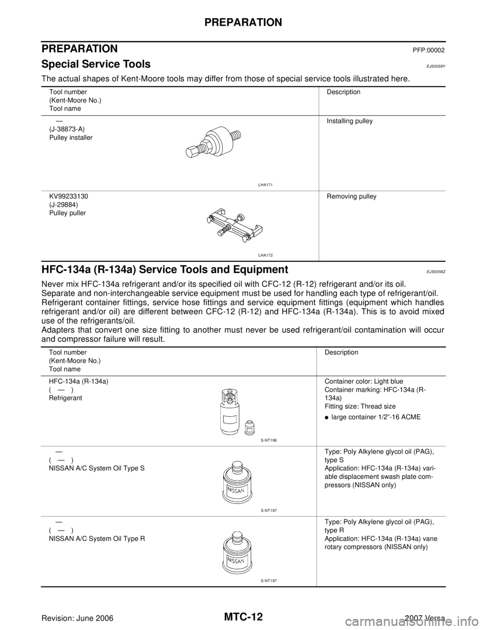
The actual shapes of Kent-Moore tools may differ from those of special service tools illustrated here.
HFC-134a (R-134a) Service Tools and EquipmentEJS0058Z
Never mix HFC-134a refrigerant and/or its specified oil with CFC-12 (R-12) refrigerant and/or its oil.
Separate and non-interchangeable service equipment must be used for handling each type of refrigerant/oil.
Refrigerant container fittings, service hose fittings and service equipment fittings (equipment which handles
refrigerant and/or oil) are different between CFC-12 (R-12) and HFC-134a (R-134a). This is to avoid mixed
use of the refrigerants/oil.
Adapters that convert one size fitting to another must never be used refrigerant/oil contamination will occur
and compressor failure will result.
Tool number
(Kent-Moore No.)
Tool nameDescription
—
(J-38873-A)
Pulley installerInstalling pulley
KV99233130
(J-29884)
Pulley pullerRemoving pulley
LHA171
LHA172
Tool number
(Kent-Moore No.)
Tool nameDescription
HFC-134a (R-134a)
(—)
RefrigerantContainer color: Light blue
Container marking: HFC-134a (R-
134a)
Fitting size: Thread size
�large container 1/2”-16 ACME
—
(—)
NISSAN A/C System Oil Type SType: Poly Alkylene glycol oil (PAG),
type S
Application: HFC-134a (R-134a) vari-
able displacement swash plate com-
pressors (NISSAN only)
—
(—)
NISSAN A/C System Oil Type RType: Poly Alkylene glycol oil (PAG),
type R
Application: HFC-134a (R-134a) vane
rotary compressors (NISSAN only)
S-NT196
S-NT197
S-NT197
Page 2430 of 2896

MTC-18
OIL
Revision: June 20062007 Versa
OILPFP:KLG00
Maintenance of Oil Quantity in CompressorEJS00579
The oil in the compressor circulates through the system with the refrigerant. Add oil to compressor when
replacing any component or after a large refrigerant leakage occurred. It is important to maintain the specified
amount.
If oil quantity is not maintained properly, the following malfunctions may result:
�Lack of oil: May lead to a seized compressor.
�Excessive oil: Inadequate cooling (thermal exchange interference)
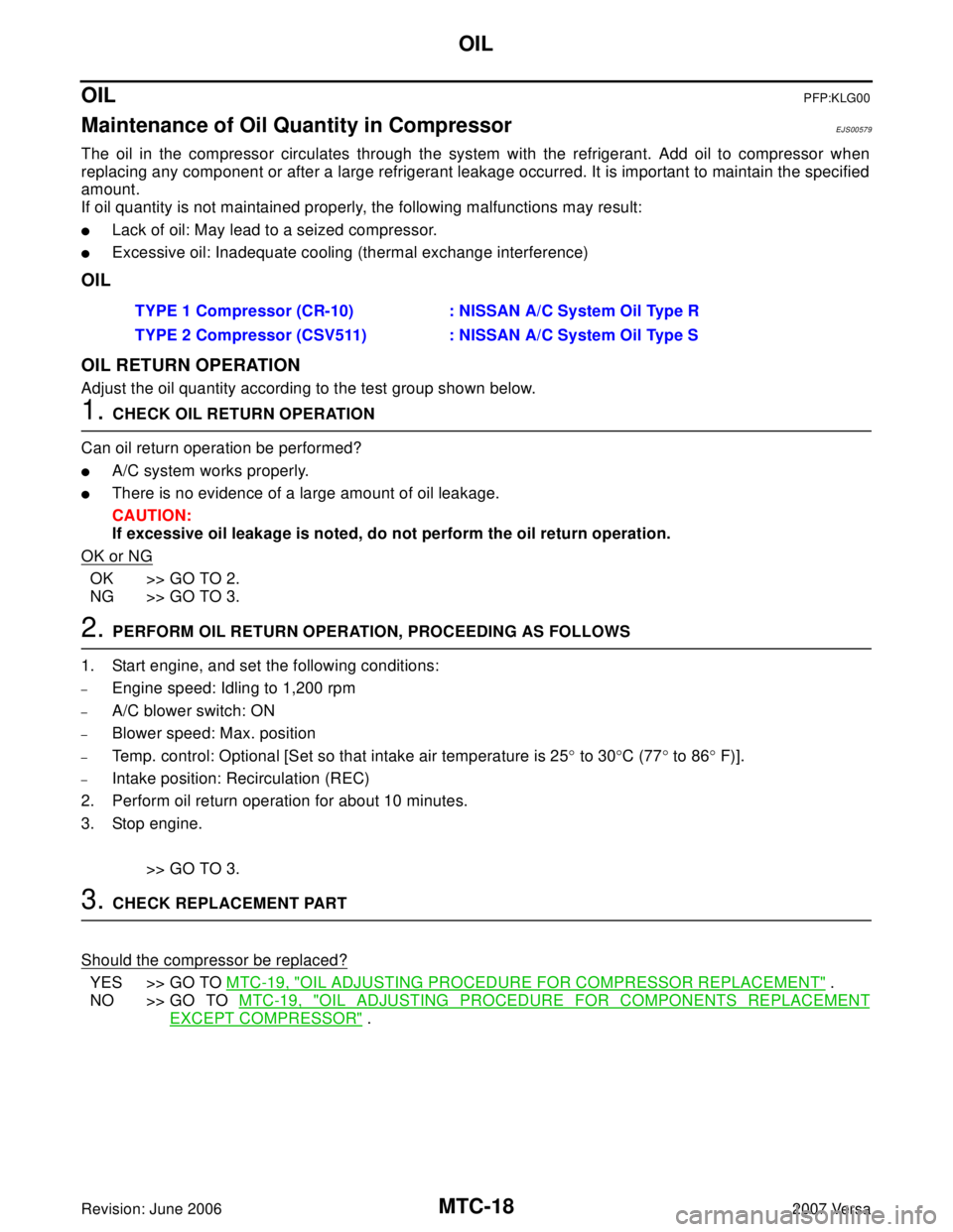
OIL
OIL RETURN OPERATION
Adjust the oil quantity according to the test group shown below.
1. CHECK OIL RETURN OPERATION
Can oil return operation be performed?
�A/C system works properly.
�There is no evidence of a large amount of oil leakage.
CAUTION:
If excessive oil leakage is noted, do not perform the oil return operation.
OK or NG
OK >> GO TO 2.
NG >> GO TO 3.
2. PERFORM OIL RETURN OPERATION, PROCEEDING AS FOLLOWS
1. Start engine, and set the following conditions:
–Engine speed: Idling to 1,200 rpm
–A/C blower switch: ON
–Blower speed: Max. position
–Temp. control: Optional [Set so that intake air temperature is 25° to 30°C (77° to 86° F)].
–Intake position: Recirculation (REC)
2. Perform oil return operation for about 10 minutes.
3. Stop engine.
>> GO TO 3.
3. CHECK REPLACEMENT PART
Should the compressor be replaced?
YES >> GO TO MTC-19, "OIL ADJUSTING PROCEDURE FOR COMPRESSOR REPLACEMENT" .
NO >> GO TO MTC-19, "
OIL ADJUSTING PROCEDURE FOR COMPONENTS REPLACEMENT
EXCEPT COMPRESSOR" . TYPE 1 Compressor (CR-10) : NISSAN A/C System Oil Type R
TYPE 2 Compressor (CSV511) : NISSAN A/C System Oil Type S
Page 2467 of 2896

TROUBLE DIAGNOSIS
MTC-55
C
D
E
F
G
H
I
K
L
MA
B
MTC
Revision: June 20062007 Versa
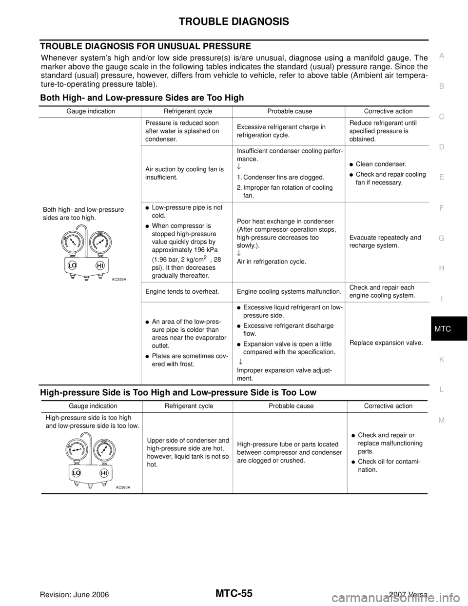
TROUBLE DIAGNOSIS FOR UNUSUAL PRESSURE
Whenever system’s high and/or low side pressure(s) is/are unusual, diagnose using a manifold gauge. The
marker above the gauge scale in the following tables indicates the standard (usual) pressure range. Since the
standard (usual) pressure, however, differs from vehicle to vehicle, refer to above table (Ambient air tempera-
ture-to-operating pressure table).
Both High- and Low-pressure Sides are Too High
High-pressure Side is Too High and Low-pressure Side is Too Low
Gauge indication Refrigerant cycle Probable cause Corrective action
Both high- and low-pressure
sides are too high.Pressure is reduced soon
after water is splashed on
condenser.Excessive refrigerant charge in
refrigeration cycle.Reduce refrigerant until
specified pressure is
obtained.
Air suction by cooling fan is
insufficient.Insufficient condenser cooling perfor-
mance.
↓
1. Condenser fins are clogged.
2. Improper fan rotation of cooling
fan.
�Clean condenser.
�Check and repair cooling
fan if necessary.
�Low-pressure pipe is not
cold.
�When compressor is
stopped high-pressure
value quickly drops by
approximately 196 kPa
(1.96 bar, 2 kg/cm
2 , 28
psi). It then decreases
gradually thereafter.Poor heat exchange in condenser
(After compressor operation stops,
high-pressure decreases too
slowly.).
↓
Air in refrigeration cycle.Evacuate repeatedly and
recharge system.
Engine tends to overheat. Engine cooling systems malfunction.Check and repair each
engine cooling system.
�An area of the low-pres-
sure pipe is colder than
areas near the evaporator
outlet.
�Plates are sometimes cov-
ered with frost.
�Excessive liquid refrigerant on low-
pressure side.
�Excessive refrigerant discharge
flow.
�Expansion valve is open a little
compared with the specification.
↓
Improper expansion valve adjust-
ment.Replace expansion valve.
AC359A
Gauge indication Refrigerant cycle Probable cause Corrective action
High-pressure side is too high
and low-pressure side is too low.
Upper side of condenser and
high-pressure side are hot,
however, liquid tank is not so
hot.High-pressure tube or parts located
between compressor and condenser
are clogged or crushed.
�Check and repair or
replace malfunctioning
parts.
�Check oil for contami-
nation.
AC360A