Page 1900 of 2896
CYLINDER BLOCK
EM-91
C
D
E
F
G
H
I
J
K
L
MA
EM
Revision: June 20062007 Versa
HOW TO SELECT MAIN BEARING
When New Cylinder Block and Crankshaft are Used
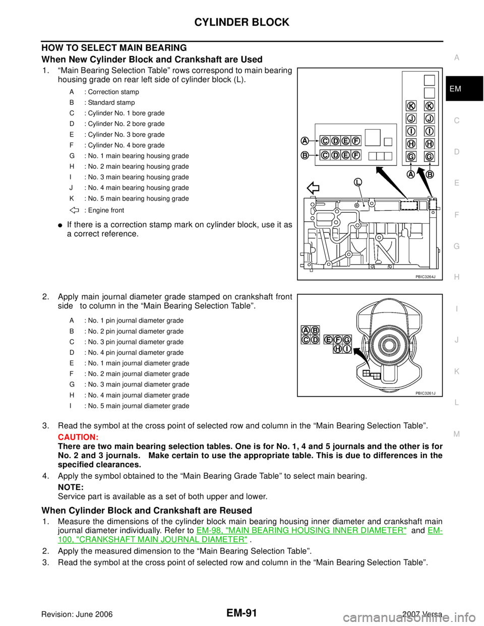
1. “Main Bearing Selection Table” rows correspond to main bearing
housing grade on rear left side of cylinder block (L).
�If there is a correction stamp mark on cylinder block, use it as
a correct reference.
2. Apply main journal diameter grade stamped on crankshaft front
side to column in the “Main Bearing Selection Table”.
3. Read the symbol at the cross point of selected row and column in the “Main Bearing Selection Table”.
CAUTION:
There are two main bearing selection tables. One is for No. 1, 4 and 5 journals and the other is for
No. 2 and 3 journals. Make certain to use the appropriate table. This is due to differences in the
specified clearances.
4. Apply the symbol obtained to the “Main Bearing Grade Table” to select main bearing.
NOTE:
Service part is available as a set of both upper and lower.
When Cylinder Block and Crankshaft are Reused
1. Measure the dimensions of the cylinder block main bearing housing inner diameter and crankshaft main
journal diameter individually. Refer to EM-98, "
MAIN BEARING HOUSING INNER DIAMETER" and EM-
100, "CRANKSHAFT MAIN JOURNAL DIAMETER" .
2. Apply the measured dimension to the “Main Bearing Selection Table”.
3. Read the symbol at the cross point of selected row and column in the “Main Bearing Selection Table”.
A : Correction stamp
B : Standard stamp
C : Cylinder No. 1 bore grade
D : Cylinder No. 2 bore grade
E : Cylinder No. 3 bore grade
F : Cylinder No. 4 bore grade
G : No. 1 main bearing housing grade
H : No. 2 main bearing housing grade
I : No. 3 main bearing housing grade
J : No. 4 main bearing housing grade
K : No. 5 main bearing housing grade
: Engine front
PBIC3264J
A : No. 1 pin journal diameter grade
B : No. 2 pin journal diameter grade
C : No. 3 pin journal diameter grade
D : No. 4 pin journal diameter grade
E : No. 1 main journal diameter grade
F : No. 2 main journal diameter grade
G : No. 3 main journal diameter grade
H : No. 4 main journal diameter grade
I : No. 5 main journal diameter grade
PBIC3261J
Page 1909 of 2896
EM-100Revision: June 2006
CYLINDER BLOCK
2007 Versa
�If it exceeds the limit, replace piston and piston pin assembly and/or cylinder block. Refer to EM-87,
"HOW TO SELECT PISTON" .
CRANKSHAFT MAIN JOURNAL DIAMETER
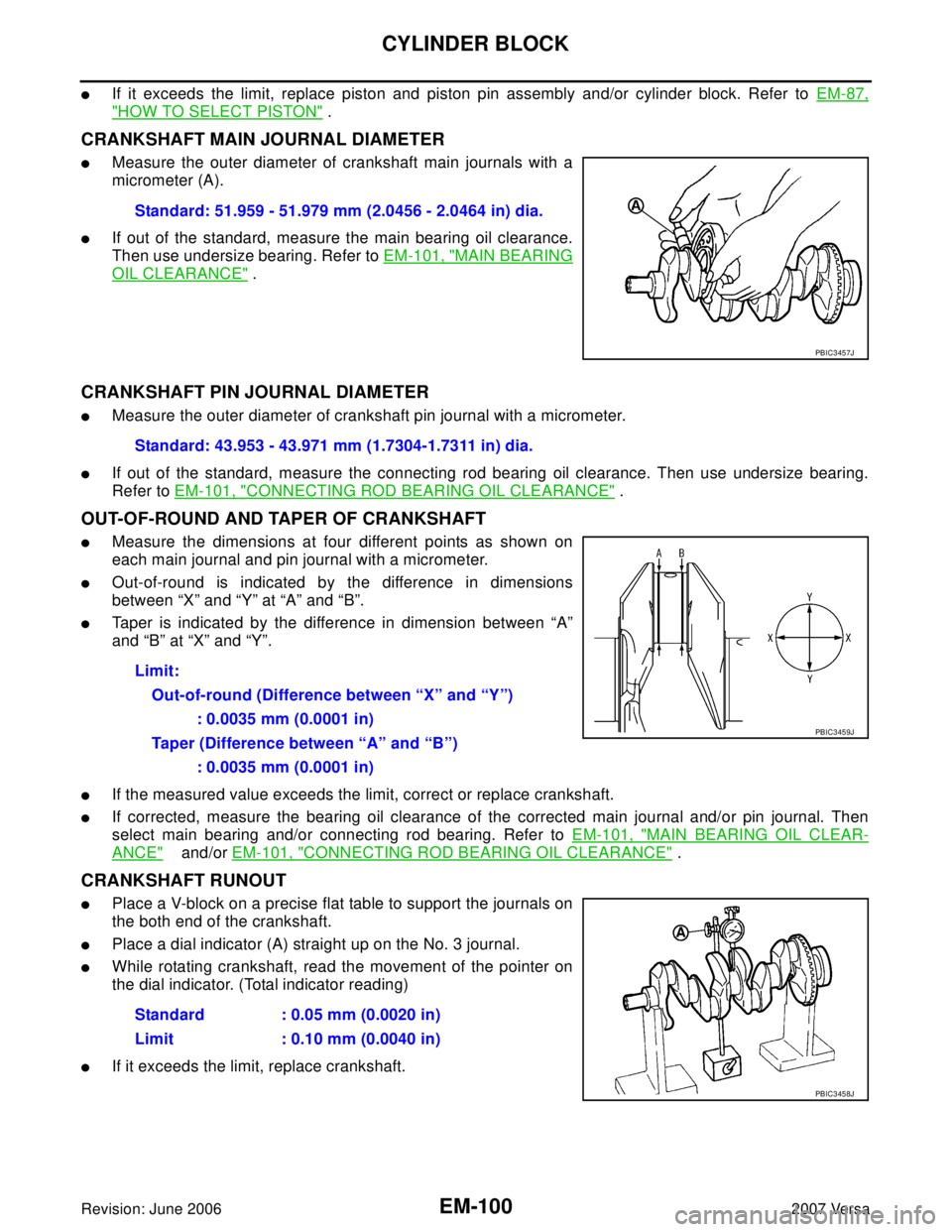
�Measure the outer diameter of crankshaft main journals with a
micrometer (A).
�If out of the standard, measure the main bearing oil clearance.
Then use undersize bearing. Refer to EM-101, "
MAIN BEARING
OIL CLEARANCE" .
CRANKSHAFT PIN JOURNAL DIAMETER
�Measure the outer diameter of crankshaft pin journal with a micrometer.
�If out of the standard, measure the connecting rod bearing oil clearance. Then use undersize bearing.
Refer to EM-101, "
CONNECTING ROD BEARING OIL CLEARANCE" .
OUT-OF-ROUND AND TAPER OF CRANKSHAFT
�Measure the dimensions at four different points as shown on
each main journal and pin journal with a micrometer.
�Out-of-round is indicated by the difference in dimensions
between “X” and “Y” at “A” and “B”.
�Taper is indicated by the difference in dimension between “A”
and “B” at “X” and “Y”.
�If the measured value exceeds the limit, correct or replace crankshaft.
�If corrected, measure the bearing oil clearance of the corrected main journal and/or pin journal. Then
select main bearing and/or connecting rod bearing. Refer to EM-101, "
MAIN BEARING OIL CLEAR-
ANCE" and/or EM-101, "CONNECTING ROD BEARING OIL CLEARANCE" .
CRANKSHAFT RUNOUT
�Place a V-block on a precise flat table to support the journals on
the both end of the crankshaft.
�Place a dial indicator (A) straight up on the No. 3 journal.
�While rotating crankshaft, read the movement of the pointer on
the dial indicator. (Total indicator reading)
�If it exceeds the limit, replace crankshaft.Standard: 51.959 - 51.979 mm (2.0456 - 2.0464 in) dia.
PBIC3457J
Standard: 43.953 - 43.971 mm (1.7304-1.7311 in) dia.
Limit:
Out-of-round (Difference between “X” and “Y”)
: 0.0035 mm (0.0001 in)
Taper (Difference between “A” and “B”)
: 0.0035 mm (0.0001 in)
PBIC3459J
Standard : 0.05 mm (0.0020 in)
Limit : 0.10 mm (0.0040 in)
PBIC3458J
Page 1912 of 2896
CYLINDER BLOCK
EM-103
C
D
E
F
G
H
I
J
K
L
MA
EM
Revision: June 20062007 Versa
MAIN BEARING CAP BOLT OUTER DIAMETER
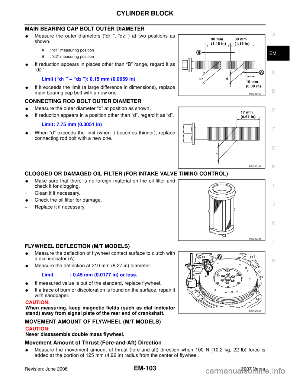
�Measure the outer diameters (“d1 ”, “d2” ) at two positions as
shown.
�If reduction appears in places other than “B” range, regard it as
“d
2 ”.
�If it exceeds the limit (a large difference in dimensions), replace
main bearing cap bolt with a new one.
CONNECTING ROD BOLT OUTER DIAMETER
�Measure the outer diameter “d” at position as shown.
�If reduction appears in a position other than “d”, regard it as “d”.
�When “d” exceeds the limit (when it becomes thinner), replace
connecting rod bolt with a new one.
CLOGGED OR DAMAGED OIL FILTER (FOR INTAKE VALVE TIMING CONTROL)
�Make sure that there is no foreign material on the oil filter and
check it for clogging.
–Clean it if necessary.
�Check the oil filter for damage.
–Replace it if necessary.
FLYWHEEL DEFLECTION (M/T MODELS)
�Measure the deflection of flywheel contact surface to clutch with
a dial indicator (A).
�Measure the deflection at 210 mm (8.27 in) diameter.
�If measured value is out of the standard, replace flywheel.
�If a trace of burn or discoloration is found on the surface, repair it
with sandpaper.
CAUTION:
When measuring, keep magnetic fields (such as dial indicator
stand) away from signal plate of the rear end of crankshaft.
MOVEMENT AMOUNT OF FLYWHEEL (M/T MODELS)
CAUTION:
Never disassemble double mass flywheel.
Movement Amount of Thrust (Fore-and-Aft) Direction
�Measure the movement amount of thrust (fore-and-aft) direction when 100 N (10.2 kg, 22 lb) force is
added at the portion of 125 mm (4.92 in) radius from the center of flywheel.
A : “d1” measuring position
B : “d2” measuring position
Limit (“d1 ” – “d2 ”): 0.15 mm (0.0059 in)
PBIC4015E
Limit: 7.75 mm (0.3051 in)
PBIC4016E
PBIC3273J
Limit : 0.45 mm (0.0177 in) or less.
PBIC4006E
Page 1913 of 2896
EM-104Revision: June 2006
CYLINDER BLOCK
2007 Versa
�If measured value is out of the standard, replace flywheel.
Movement Amount in Radial (Rotation) Direction
Check the movement amount of radial (rotation) direction with the following procedure:
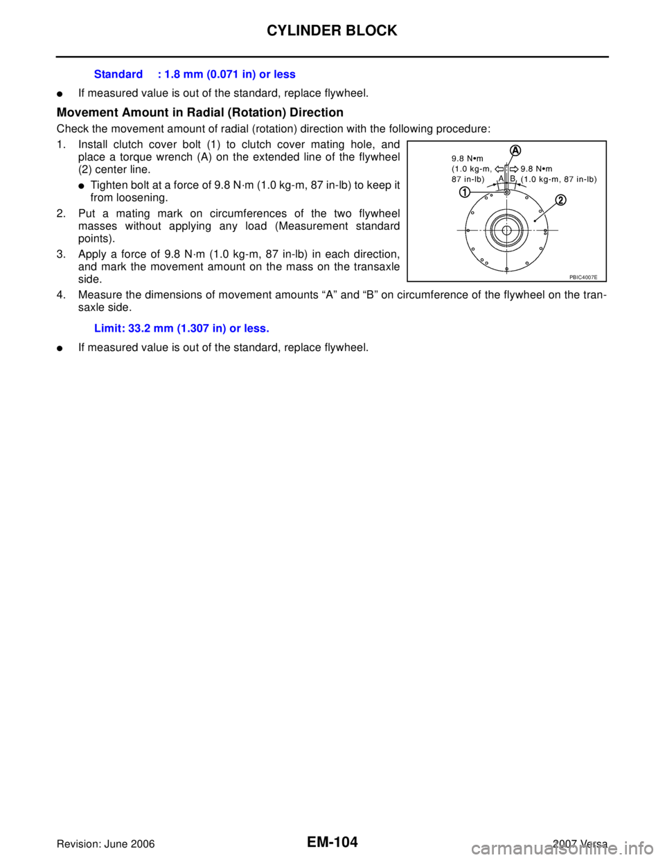
1. Install clutch cover bolt (1) to clutch cover mating hole, and
place a torque wrench (A) on the extended line of the flywheel
(2) center line.
�Tighten bolt at a force of 9.8 N·m (1.0 kg-m, 87 in-lb) to keep it
from loosening.
2. Put a mating mark on circumferences of the two flywheel
masses without applying any load (Measurement standard
points).
3. Apply a force of 9.8 N·m (1.0 kg-m, 87 in-lb) in each direction,
and mark the movement amount on the mass on the transaxle
side.
4. Measure the dimensions of movement amounts “A” and “B” on circumference of the flywheel on the tran-
saxle side.
�If measured value is out of the standard, replace flywheel.Standard : 1.8 mm (0.071 in) or less
Limit: 33.2 mm (1.307 in) or less.
PBIC4007E
Page 1915 of 2896
EM-106Revision: June 2006
SERVICE DATA AND SPECIFICATIONS (SDS)
2007 Versa
VA LV E
Va lv e Tim in g
Unit: degree
( ): Valve timing control “ON”
Valve Dimensions
Unit: mm (in) Normal cylinder head height “H” 130.9 (5.15) — Items Standard Limit
PBIC0924E
Va l v e t i m i n g
ab c de f
212 224 -8 (32) 52 (12) 7 25
PBIC4542E
Valve head diameter “D”Intake 33.8 - 34.1 (1.331 - 1.343)
Exhaust 27.6 - 27.9 (1.087 - 1.098)
Valve length “L”Intake 106.21 (4.181)
Exhaust 105.26 (4.144)
Valve stem diameter “d”Intake 5.465 - 5.480 (0.2152 - 0.2157)
Exhaust 5.455 - 5.470 (0.2148 - 0.2154)
Valve seat angle “α”45°15′ - 45°45′
Valve margin “T”Intake 1.1 (0.043)
Exhaust 1.2 (0.047)
SEM 18 8A
Page 1973 of 2896
GI-2Revision: June 20062007 Versa VEHICLE IDENTIFICATION NUMBER
ARRANGEMENT ................................................. 48
IDENTIFICATION PLATE .................................... 49
ENGINE SERIAL NUMBER ................................ 49
AUTOMATIC TRANSAXLE NUMBER ................. 49
MANUAL TRANSAXLE NUMBER ....................... 49CVT NUMBER .....................................................50
Dimensions .............................................................50
Wheels & Tires ........................................................50
TERMINOLOGY ........................................................51
SAE J1930 Terminology List ...................................51
Page 2021 of 2896
GI-50
IDENTIFICATION INFORMATION
Revision: June 20062007 Versa
CVT NUMBER
Dimensions EAS00205
Unit: mm (in)
Wheels & Tires EAS00206
LAIA0074E
Overall length4,295 (169.1)
Overall width1,694.2 (66.7)
Overall height1,534.1 (60.4)
Front tread1,480 (58.3)
Rear tread1,485 (58.5)
Wheelbase2,599.9 (102.4)
Road wheel
Size15 x 5.5 JJ
Offset mm (in) 40 (1.57)
Tire s ize
Conventional185/65 R15
SpareT125/70D15
Page 2232 of 2896
LT-24
HEADLAMP (FOR USA)
Revision: June 20062007 Versa
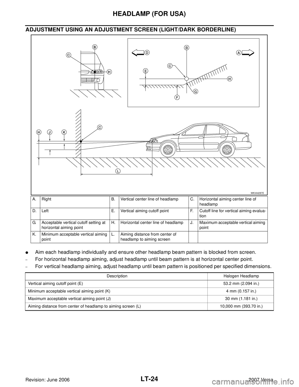
ADJUSTMENT USING AN ADJUSTMENT SCREEN (LIGHT/DARK BORDERLINE)
�Aim each headlamp individually and ensure other headlamp beam pattern is blocked from screen.
–For horizontal headlamp aiming, adjust headlamp until beam pattern is at horizontal center point.
–For vertical headlamp aiming, adjust headlamp until beam pattern is positioned per specified dimensions.
A. Right B. Vertical center line of headlamp C. Horizontal aiming center line of
headlamp
D. Left E. Vertical aiming cutoff point F. Cutoff line for vertical aiming evalua-
tion
G. Acceptable vertical cutoff setting at
horizontal aiming pointH. Horizontal center line of headlamp J. Maximum acceptable vertical aiming
point
K. Minimum acceptable vertical aiming
pointL. Aiming distance from center of
headlamp to aiming screen
WKIA4287E
Description Halogen Headlamp
Vertical aiming cutoff point (E)53.2 mm (2.094 in.)
Minimum acceptable vertical aiming point (K) 4 mm (0.157 in.)
Maximum acceptable vertical aiming point (J) 30 mm (1.181 in.)
Aiming distance from center of headlamp to aiming screen (L) 10,000 mm (393.70 in.)