WT-18
TROUBLE DIAGNOSES
Revision: June 20062007 Versa
Self-Diagnostic Results Mode
NOTE:
Before performing the self-diagnosis, be sure to register the ID or else the actual malfunction location may be different from that dis-
played on CONSULT-II.
Data Monitor Mode
NOTE:
Before performing the self-diagnosis, be sure to register the ID, or the actual malfunction location may be different from that displayed on
CONSULT-II.Diagnostic item
Diagnostic item is detected when ···Reference
page Program card UED06A or
earlierProgram card UED06B or later
FLAT - TIRE - FL [C1704]
FLAT - TIRE - FR [C1705]
FLAT - TIRE - RR [C1706]
FLAT - TIRE - RL [C1707]LOW - PRESSURE - FL [C1704]
LOW - PRESSURE - FR [C1705]
LOW - PRESSURE - RR [C1706]
LOW - PRESSURE - RL [C1707]FL tire pressure 193 kPa (2.0 kg/cm
2 , 28 psi) or less
FR tire pressure 193 kPa (2.0 kg/cm2 , 28 psi) or less
RR tire pressure 193 kPa (2.0 kg/cm2 , 28 psi) or less
RL tire pressure 193 kPa (2.0 kg/cm2 , 28 psi) or less—
[NO-DATA] - FL [C1708]
[NO-DATA] - FR [C1709]
[NO-DATA] - RR [C1710]
[NO-DATA] - RL [C1711]Data from FL transmitter cannot be received.
Data from FR transmitter cannot be received.
Data from RR transmitter cannot be received.
Data from RL transmitter cannot be received.WT-20
[CHECKSUM- ERR] - FL
[CHECKSUM- ERR] - FR
[CHECKSUM- ERR] - RR
[CHECKSUM- ERR] - RLChecksum data from FL transmitter is malfunctioning.
Checksum data from FR transmitter is malfunctioning.
Checksum data from RR transmitter is malfunctioning.
Checksum data from RL transmitter is malfunctioning.WT-20
[PRESSDATA- ERR] - FL
[PRESSDATA- ERR] - FR
[PRESSDATA- ERR] - RR
[PRESSDATA- ERR] - RLAir pressure data from FL transmitter is malfunctioning.
Air pressure data from FR transmitter is malfunctioning.
Air pressure data from RR transmitter is malfunctioning.
Air pressure data from RL transmitter is malfunctioning.WT-21
[CODE- ERR] - FL
[CODE- ERR] - FR
[CODE- ERR] - RR
[CODE- ERR] - RLFunction code data from FL transmitter is malfunctioning.
Function code data from FR transmitter is malfunctioning.
Function code data from RR transmitter is malfunctioning.
Function code data from RL transmitter is malfunctioning.WT-20
[BATT - VOLT - LOW] - FL
[BATT - VOLT - LOW] - FR
[BATT - VOLT - LOW] - RR
[BATT - VOLT - LOW] - RLBattery voltage of FL transmitter drops.
Battery voltage of FR transmitter drops.
Battery voltage of RR transmitter drops.
Battery voltage of RL transmitter drops.WT-20
VHCL_SPEED_SIG_ERR [C1729] Vehicle speed signal is in error.WT-22
MONITOR CONDITION SPECIFICATION
VHCL SPEED Drive vehicle. Vehicle speed (km/h or MPH)
AIR PRESS FL
AIR PRESS FR
AIR PRESS RR
AIR PRESS RL
�Drive vehicle for a few minutes.
Tire pressure (kPa or psi) or
�Ignition switch ON and activation tool
is transmitting activation signals.
ID REGST FL1
ID REGST FR1
ID REGST RR1
ID REGST RL1
Ignition switch ONRegistration ID: DONE
No registration ID: YET
WAR NIN G LAMPLow tire pressure warning lamp on: ON
Low tire pressure warning lamp off: OFF
BUZZERBuzzer in combination meter on: ON
Buzzer in combination meter off: OFF
WW-4
FRONT WIPER AND WASHER SYSTEM
Revision: June 20062007 Versa
FRONT WIPER AND WASHER SYSTEMPFP:28810
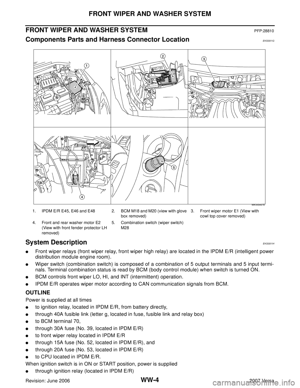
Components Parts and Harness Connector LocationEKS00I1G
System DescriptionEKS00I1H
�Front wiper relays (front wiper relay, front wiper high relay) are located in the IPDM E/R (intelligent power
distribution module engine room).
�Wiper switch (combination switch) is composed of a combination of 5 output terminals and 5 input termi-
nals. Terminal combination status is read by BCM (body control module) when switch is turned ON.
�BCM controls front wiper LO, HI, and INT (intermittent) operation.
�IPDM E/R operates wiper motor according to CAN communication signals from BCM.
OUTLINE
Power is supplied at all times
�to ignition relay, located in IPDM E/R, from battery directly,
�through 40A fusible link (letter g, located in fuse, fusible link and relay box)
�to BCM terminal 70,
�through 30A fuse (No. 39, located in IPDM E/R)
�to front wiper relay located in IPDM E/R
�through 15A fuse (No. 52, located in IPDM E/R), and
�through 20A fuse (No. 53, located in IPDM E/R)
�to CPU located in IPDM E/R.
When ignition switch is in ON or START position, power is supplied
�through ignition relay (located in IPDM E/R)
1. IPDM E/R E45, E46 and E48 2. BCM M18 and M20 (view with glove
box removed)3. Front wiper motor E1 (View with
cowl top cover removed)
4. Front and rear washer motor E2
(View with front fender protector LH
removed)5. Combination switch (wiper switch)
M28
WKIA5467E