Page 1215 of 2896
EC-46Revision: June 2006
NVIS (NISSAN VEHICLE IMMOBILIZER SYSTEM-NATS)
2007 Versa
NVIS (NISSAN VEHICLE IMMOBILIZER SYSTEM-NATS)PFP:25386
DescriptionUBS00RWM
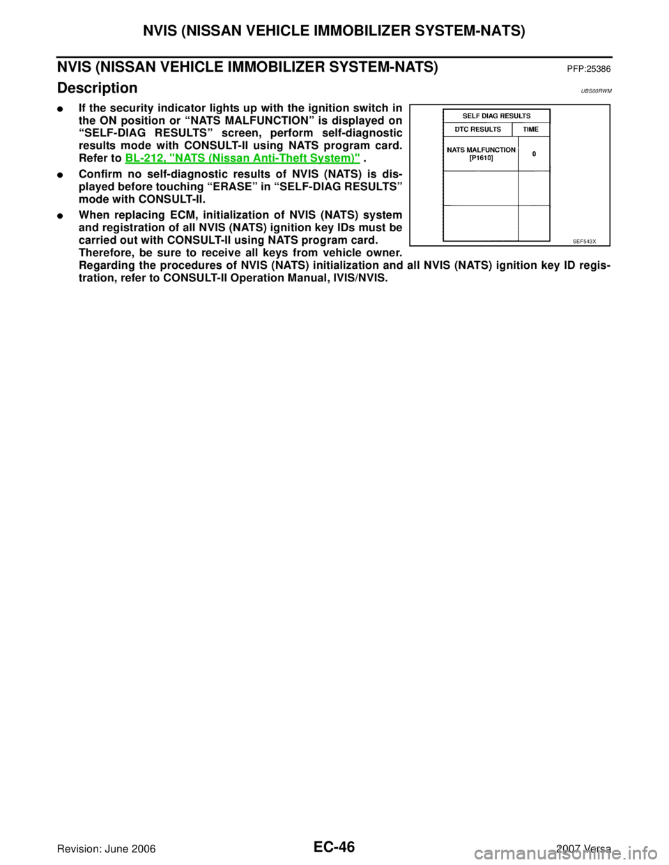
�If the security indicator lights up with the ignition switch in
the ON position or “NATS MALFUNCTION” is displayed on
“SELF-DIAG RESULTS” screen, perform self-diagnostic
results mode with CONSULT-II using NATS program card.
Refer to BL-212, "
NATS (Nissan Anti-Theft System)" .
�Confirm no self-diagnostic results of NVIS (NATS) is dis-
played before touching “ERASE” in “SELF-DIAG RESULTS”
mode with CONSULT-II.
�When replacing ECM, initialization of NVIS (NATS) system
and registration of all NVIS (NATS) ignition key IDs must be
carried out with CONSULT-II using NATS program card.
Therefore, be sure to receive all keys from vehicle owner.
Regarding the procedures of NVIS (NATS) initialization and all NVIS (NATS) ignition key ID regis-
tration, refer to CONSULT-II Operation Manual, IVIS/NVIS.
SEF 5 43 X
Page 1231 of 2896
 SYSTEM
2007 Versa
ON BOARD DIAGNOSTIC SYSTEM FUNCTION
The on board diagnostic system has the following three functions.
When there is an open circuit")
EC-62Revision: June 2006
ON BOARD DIAGNOSTIC (OBD) SYSTEM
2007 Versa
ON BOARD DIAGNOSTIC SYSTEM FUNCTION
The on board diagnostic system has the following three functions.
When there is an open circuit on MIL circuit, the ECM cannot warn the driver by MIL lighting up when there is
malfunction on engine control system.
Therefore, when electrical controlled throttle and part of ECM related diagnoses are continuously detected as
NG for 5 trips, ECM warns the driver that engine control system malfunctions and MIL circuit is open by means
of operating fail-safe function.
The fail-safe function also operates when above diagnoses except MIL circuit are detected, and demands the
driver to repair the malfunction.
MIL Flashing Without DTC
When any SRT codes are not set, MIL may flash without DTC. For the details, refer to EC-56, "How to Display
SRT Status" .
HOW TO SWITCH DIAGNOSTIC TEST MODE
NOTE:
�It is better to count the time accurately with a clock.
�It is impossible to switch the diagnostic mode when an accelerator pedal position sensor circuit
has a malfunction.
�Always ECM returns to Diagnostic Test Mode I after ignition switch is turned OFF.
How to Set Diagnostic Test Mode II (Self-diagnostic Results)
1. Confirm that accelerator pedal is fully released, turn ignition switch ON and wait 3 seconds.
2. Repeat the following procedure quickly five times within 5 seconds.
a. Fully depress the accelerator pedal.
b. Fully release the accelerator pedal.
3. Wait 7 seconds, fully depress the accelerator pedal and keep it for approx. 10 seconds until the MIL starts
blinking.
Diagnostic Test
ModeKEY and ENG.
Statu sFunction Explanation of Function
Mode I Ignition switch in
ON position
Engine stoppedBULB CHECK This function checks the MIL bulb for damage (blown,
open circuit, etc.).
If the MIL does not come on, check MIL circuit.
Engine running MALFUNCTION
WARNINGThis is a usual driving condition. When a malfunction is
detected twice in two consecutive driving cycles (two trip
detection logic), the MIL will light up to inform the driver
that a malfunction has been detected.
The following malfunctions will light up or blink the MIL in
the 1st trip.
�Misfire (Possible three way catalyst damage)
�One trip detection diagnoses
Mode II Ignition switch in
ON position
Engine stoppedSELF-DIAGNOSTIC
RESULTSThis function allows DTCs and 1st trip DTCs to be read.
Engine operating condition in fail-safe mode Engine speed will not rise more than 2,500 rpm due to the fuel cut
Page 1241 of 2896

EC-72Revision: June 2006
BASIC SERVICE PROCEDURE
2007 Versa
6. PERFORM IDLE AIR VOLUME LEARNING
Refer to EC-78, "
Idle Air Volume Learning" .
Is Idle Air Volume Learning carried out successfully?
Ye s o r N o
Yes >> GO TO 7.
No >> 1. Follow the instruction of Idle Air Volume Learning.
2. GO TO 4.
7. CHECK TARGET IDLE SPEED AGAIN
With CONSULT-II
1. Start engine and warm it up to normal operating temperature.
2. Read idle speed in “DATA MONITOR” mode with CONSULT-II.
Refer to EC-75, "
IDLE SPEED" .
Without CONSULT-II
1. Start engine and warm it up to normal operating temperature.
2. Check idle speed. Refer to EC-75, "
IDLE SPEED" .
OK or NG
OK >> GO TO 10.
NG >> GO TO 8.
8. DETECT MALFUNCTIONING PART
Check the following.
�Check crankshaft position sensor (POS) and circuit.
Refer to EC-319, "
DTC P0335 CKP SENSOR (POS)" .
�Check camshaft position sensor (PHASE) and circuit.
Refer to EC-327, "
DTC P0340 CMP SENSOR (PHASE)" .
OK or NG
OK >> GO TO 9.
NG >> 1. Repair or replace.
2. GO TO 4.
9. CHECK ECM FUNCTION
1. Substitute another known-good ECM to check ECM function. (ECM may be the cause of an incident, but
this is a rare case.)
2. Perform initialization of NVIS (NATS) system and registration of all NVIS (NATS) ignition key IDs.
Refer to BL-214, "
ECM Re-communicating Function" .
>> GO TO 4. M/T: 700 ± 50 rpm (in Neutral position)
A/T: 700 ± 50 rpm (in P or N position)
CVT: 700 ± 50 rpm (in P or N position)
M/T: 700 ± 50 rpm (in Neutral position)
A/T: 700 ± 50 rpm (in P or N position)
CVT: 700 ± 50 rpm (in P or N position)
SEF 1 74 Y
Page 1244 of 2896
BASIC SERVICE PROCEDURE
EC-75
C
D
E
F
G
H
I
J
K
L
MA
EC
Revision: June 20062007 Versa
18. CHECK ECM FUNCTION
1. Substitute another known-good ECM to check ECM function. (ECM may be the cause of an incident, but
this is a rare case.)
2. Perform initialization of NVIS (NATS) system and registration of all NVIS (NATS) ignition key IDs.
Refer to BL-214, "
ECM Re-communicating Function" .
>> GO TO 4.
19. INSPECTION END
Did you replace ECM, referring this Basic Inspection procedure?
Ye s o r N o
Ye s > > 1 . P e r f o r m EC-77, "VIN Registration" .
2.INSPECTION END
No >>INSPECTION END
Idle Speed and Ignition Timing CheckUBS00QBL
IDLE SPEED
With CONSULT-II
Check idle speed in “DATA MONITOR” mode with CONSULT-II.
With GST
Check idle speed in Service $01 with GST.
IGNITION TIMING
Any of following two methods may be used.
Method A
1. Attach timing light to loop wire (1) as shown.
� : Vehicle front
SEF 0 58 Y
PBIB3320E
Page 1246 of 2896

Procedure After Replacing ECMUBS00QO6
When replacing ECM, the following procedure must be pe")
BASIC SERVICE PROCEDURE
EC-77
C
D
E
F
G
H
I
J
K
L
MA
EC
Revision: June 20062007 Versa
�Timing indicator (1)
Procedure After Replacing ECMUBS00QO6
When replacing ECM, the following procedure must be performed.
1. Perform initialization of NVIS (NATS) system and registration of all NVIS (NATS) ignition key IDs.
Refer to BL-214, "
ECM Re-communicating Function" .
2. Perform EC-77, "
VIN Registration" .
3. Perform EC-77, "
Accelerator Pedal Released Position Learning" .
4. Perform EC-78, "
Throttle Valve Closed Position Learning" .
5. Perform EC-78, "
Idle Air Volume Learning" .
VIN RegistrationUBS00QO7
DESCRIPTION
VIN Registration is an operation to registering VIN in ECM. It must be performed each time ECM is replaced.
NOTE:
Accurate VIN which is registered in ECM may be required for Inspection & Maintenance (I/M).
OPERATION PROCEDURE
With CONSULT-II
1. Check the VIN of the vehicle and note it. Refer to GI-47, "IDENTIFICATION INFORMATION" .
2. Turn ignition switch ON and engine stopped.
3. Select “VIN REGISTRATION” in “WORK SUPPORT” mode.
4. Follow the instruction of CONSULT-II display.
Accelerator Pedal Released Position LearningUBS00QO8
DESCRIPTION
Accelerator Pedal Released Position Learning is an operation to learn the fully released position of the accel-
erator pedal by monitoring the accelerator pedal position sensor output signal. It must be performed each time
harness connector of accelerator pedal position sensor or ECM is disconnected.
OPERATION PROCEDURE
1. Make sure that accelerator pedal is fully released.
2. Turn ignition switch ON and wait at least 2 seconds.
3. Turn ignition switch OFF and wait at least 10 seconds.
4. Turn ignition switch ON and wait at least 2 seconds.
5. Turn ignition switch OFF and wait at least 10 seconds.
PBIB3263E
PBIB2242E
Page 1309 of 2896

EC-140Revision: June 2006
TROUBLE DIAGNOSIS - SPECIFICATION VALUE
2007 Versa
20. CHECK “A/F ALPHA-B1” AND “B/FUEL SCHDL”
Select “A/F ALPHA-B1” and “B/FUEL SCHDL” in “DATA MONITOR (SPEC)” mode, and make sure that the
each indication is within the SP value.
OK or NG
OK >>INSPECTION END
NG (“B/FUEL SCHDL” is more, “A/F ALPHA-B1” is less than the SP value)>>GO TO 21.
21. DISCONNECT AND RECONNECT MASS AIR FLOW SENSOR HARNESS CONNECTOR
1. Stop the engine.
2. Disconnect mass air flow sensor harness connector. Check pin terminal and connector for damage and
then reconnect it again.
>> GO TO 22.
22. CHECK “A/F ALPHA-B1”
1. Start engine.
2. Select “A/F ALPHA-B1” in “DATA MONITOR (SPEC)” mode, and make sure that the indication is within
the SP value.
OK or NG
OK >> 1. Detect malfunctioning part of mass air flow sensor circuit and repair it. Refer to EC-178, "DTC
P0101 MAF SENSOR" .
2. GO TO 29.
NG >> GO TO 23.
23. CHECK “MAS A/F SE-B1”
Select “MAS A/F SE-B1” in “DATA MONITOR (SPEC)” mode, and
make sure that the indication is within the SP value.
OK or NG
OK >> GO TO 24.
NG (More than the SP value)>>Replace mass air flow sensor, and
then GO TO 29.
24. REPLACE ECM
1. Replace ECM.
2. Perform initialization of NVIS(NATS) system and registration of all NVIS(NATS) ignition key IDs.
Refer to BL-214, "
ECM Re-communicating Function" .
3. Perform EC-77, "
VIN Registration" .
4. Perform EC-77, "
Accelerator Pedal Released Position Learning" .
5. Perform EC-78, "
Throttle Valve Closed Position Learning" .
6. Perform EC-78, "
Idle Air Volume Learning" .
>> GO TO 29.
PBIB2370E
Page 1324 of 2896

DTC U1010 CAN COMMUNICATION
EC-155
C
D
E
F
G
H
I
J
K
L
MA
EC
Revision: June 20062007 Versa
Diagnostic ProcedureUBS00QC5
1. INSPECTION START
With CONSULT-II
1. Turn ignition switch ON.
2. Select “SELF-DIAG RESULTS” mode with CONSULT-II.
3. Touch “ERASE”.
4.Perform DTC Confirmation Procedure.
See EC-154, "
DTC Confirmation Procedure" .
5. Is the 1st trip DTC U1010 displayed again?
With GST
1. Turn ignition switch ON.
2. Select Service $04 with GST.
3.Perform DTC Confirmation Procedure.
See EC-154, "
DTC Confirmation Procedure" .
4. Is the 1st trip DTC U1010 displayed again?
Ye s o r N o
Yes >> GO TO 2.
No >>INSPECTION END
2. REPLACE ECM
1. Replace ECM.
2. Perform initialization of NVIS (NATS) system and registration of all NVIS (NATS) ignition key IDs.
Refer to BL-214, "
ECM Re-communicating Function" .
3. Perform EC-77, "
VIN Registration" .
4. Perform EC-77, "
Accelerator Pedal Released Position Learning" .
5. Perform EC-78, "
Throttle Valve Closed Position Learning" .
6. Perform EC-78, "
Idle Air Volume Learning" .
>>INSPECTION END
Page 1593 of 2896
EC-424Revision: June 2006
DTC P0506 ISC SYSTEM
2007 Versa
Diagnostic ProcedureUBS00QK8
1. CHECK INTAKE AIR LEAK
1. Start engine and let it idle.
2. Listen for an intake air leak after the mass air flow sensor.
OK or NG
OK >> GO TO 2.
NG >> Discover air leak location and repair.
2. REPLACE ECM
1. Stop engine.
2. Replace ECM.
3. Perform initialization of NVIS (NATS) system and registration of all NVIS (NATS) ignition key IDs.
Refer to BL-214, "
ECM Re-communicating Function" .
4. Perform EC-77, "
VIN Registration" .
5. Perform EC-77, "
Accelerator Pedal Released Position Learning" .
6. Perform EC-78, "
Throttle Valve Closed Position Learning" .
7. Perform EC-78, "
Idle Air Volume Learning" .
>>INSPECTION END