Page 224 of 2896

TROUBLE DIAGNOSIS FOR SYMPTOMS
AT-211
D
E
F
G
H
I
J
K
L
MA
B
AT
Revision: June 20062007 Versa
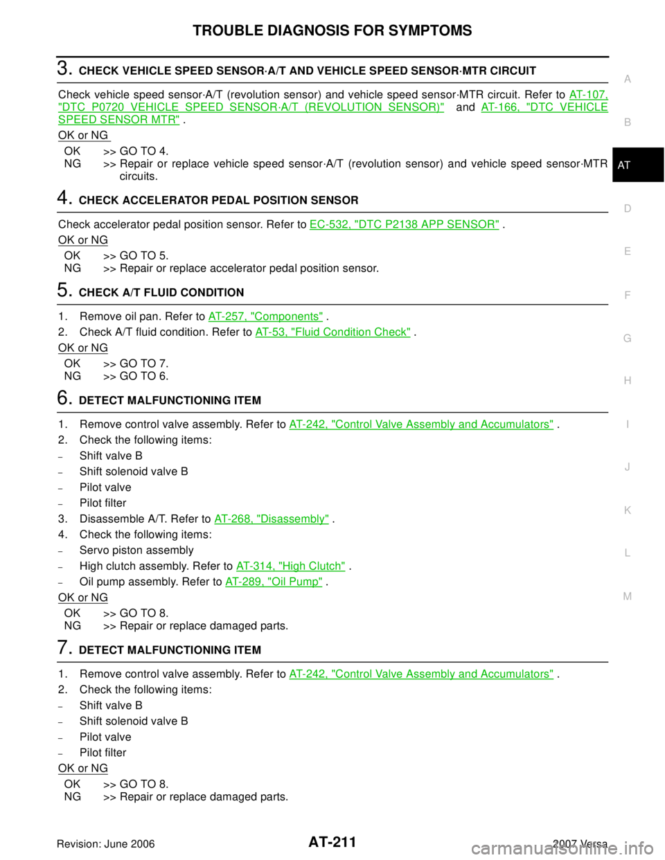
3. CHECK VEHICLE SPEED SENSOR·A/T AND VEHICLE SPEED SENSOR·MTR CIRCUIT
Check vehicle speed sensor·A/T (revolution sensor) and vehicle speed sensor·MTR circuit. Refer to AT-107,
"DTC P0720 VEHICLE SPEED SENSOR·A/T (REVOLUTION SENSOR)" and AT-166, "DTC VEHICLE
SPEED SENSOR MTR" .
OK or NG
OK >> GO TO 4.
NG >> Repair or replace vehicle speed sensor·A/T (revolution sensor) and vehicle speed sensor·MTR
circuits.
4. CHECK ACCELERATOR PEDAL POSITION SENSOR
Check accelerator pedal position sensor. Refer to EC-532, "
DTC P2138 APP SENSOR" .
OK or NG
OK >> GO TO 5.
NG >> Repair or replace accelerator pedal position sensor.
5. CHECK A/T FLUID CONDITION
1. Remove oil pan. Refer to AT-257, "
Components" .
2. Check A/T fluid condition. Refer to AT-53, "
Fluid Condition Check" .
OK or NG
OK >> GO TO 7.
NG >> GO TO 6.
6. DETECT MALFUNCTIONING ITEM
1. Remove control valve assembly. Refer to AT-242, "
Control Valve Assembly and Accumulators" .
2. Check the following items:
–Shift valve B
–Shift solenoid valve B
–Pilot valve
–Pilot filter
3. Disassemble A/T. Refer to AT- 2 6 8 , "
Disassembly" .
4. Check the following items:
–Servo piston assembly
–High clutch assembly. Refer to AT- 3 1 4 , "High Clutch" .
–Oil pump assembly. Refer to AT-289, "Oil Pump" .
OK or NG
OK >> GO TO 8.
NG >> Repair or replace damaged parts.
7. DETECT MALFUNCTIONING ITEM
1. Remove control valve assembly. Refer to AT-242, "
Control Valve Assembly and Accumulators" .
2. Check the following items:
–Shift valve B
–Shift solenoid valve B
–Pilot valve
–Pilot filter
OK or NG
OK >> GO TO 8.
NG >> Repair or replace damaged parts.
Page 226 of 2896

TROUBLE DIAGNOSIS FOR SYMPTOMS
AT-213
D
E
F
G
H
I
J
K
L
MA
B
AT
Revision: June 20062007 Versa
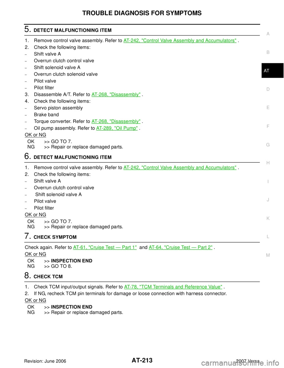
5. DETECT MALFUNCTIONING ITEM
1. Remove control valve assembly. Refer to AT-242, "
Control Valve Assembly and Accumulators" .
2. Check the following items:
–Shift valve A
–Overrun clutch control valve
–Shift solenoid valve A
–Overrun clutch solenoid valve
–Pilot valve
–Pilot filter
3. Disassemble A/T. Refer to AT- 2 6 8 , "
Disassembly" .
4. Check the following items:
–Servo piston assembly
–Brake band
–Torque converter. Refer to AT- 2 6 8 , "Disassembly" .
–Oil pump assembly. Refer to AT-289, "Oil Pump" .
OK or NG
OK >> GO TO 7.
NG >> Repair or replace damaged parts.
6. DETECT MALFUNCTIONING ITEM
1. Remove control valve assembly. Refer to AT-242, "
Control Valve Assembly and Accumulators" .
2. Check the following items:
–Shift valve A
–Overrun clutch control valve
– Shift solenoid valve A
–Pilot valve
–Pilot filter
OK or NG
OK >> GO TO 7.
NG >> Repair or replace damaged parts.
7. CHECK SYMPTOM
Check again. Refer to AT- 6 1 , "
Cruise Test — Part 1" and AT-64, "Cruise Test — Part 2" .
OK or NG
OK >>INSPECTION END
NG >> GO TO 8.
8. CHECK TCM
1. Check TCM input/output signals. Refer to AT- 7 8 , "
TCM Terminals and Reference Value" .
2. If NG, recheck TCM pin terminals for damage or loose connection with harness connector.
OK or NG
OK >>INSPECTION END
NG >> Repair or replace damaged parts.
Page 227 of 2896

AT-214
TROUBLE DIAGNOSIS FOR SYMPTOMS
Revision: June 20062007 Versa
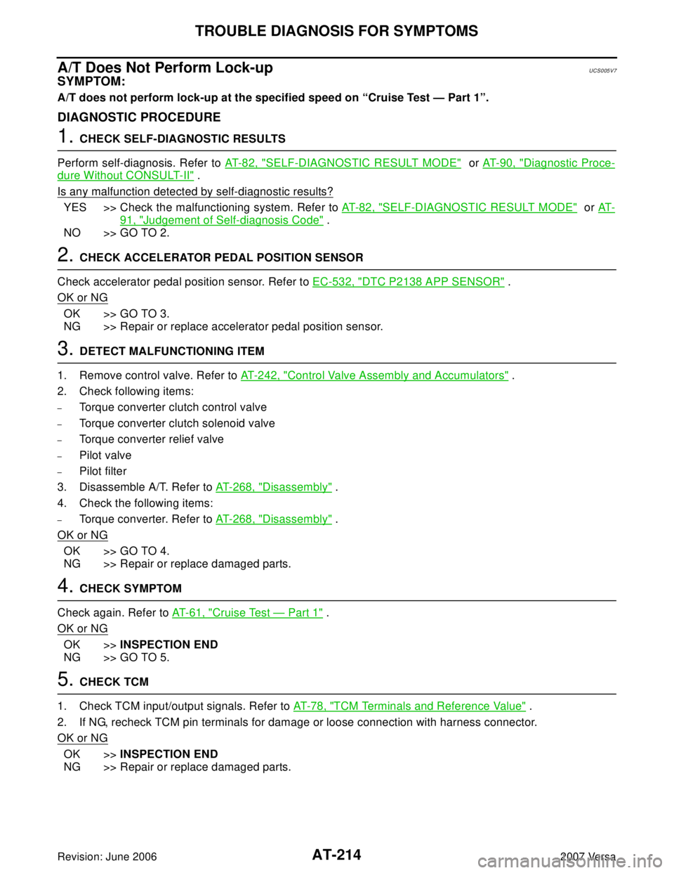
A/T Does Not Perform Lock-upUCS005V7
SYMPTOM:
A/T does not perform lock-up at the specified speed on “Cruise Test — Part 1”.
DIAGNOSTIC PROCEDURE
1. CHECK SELF-DIAGNOSTIC RESULTS
Perform self-diagnosis. Refer to AT- 8 2 , "
SELF-DIAGNOSTIC RESULT MODE" or AT-90, "Diagnostic Proce-
dure Without CONSULT-II" .
Is any malfunction detected by self-diagnostic results?
YES >> Check the malfunctioning system. Refer to AT- 8 2 , "SELF-DIAGNOSTIC RESULT MODE" or AT -
91, "Judgement of Self-diagnosis Code" .
NO >> GO TO 2.
2. CHECK ACCELERATOR PEDAL POSITION SENSOR
Check accelerator pedal position sensor. Refer to EC-532, "
DTC P2138 APP SENSOR" .
OK or NG
OK >> GO TO 3.
NG >> Repair or replace accelerator pedal position sensor.
3. DETECT MALFUNCTIONING ITEM
1. Remove control valve. Refer to AT-242, "
Control Valve Assembly and Accumulators" .
2. Check following items:
–Torque converter clutch control valve
–Torque converter clutch solenoid valve
–Torque converter relief valve
–Pilot valve
–Pilot filter
3. Disassemble A/T. Refer to AT-268, "
Disassembly" .
4. Check the following items:
–Torque converter. Refer to AT-268, "Disassembly" .
OK or NG
OK >> GO TO 4.
NG >> Repair or replace damaged parts.
4. CHECK SYMPTOM
Check again. Refer to AT-61, "
Cruise Test — Part 1" .
OK or NG
OK >>INSPECTION END
NG >> GO TO 5.
5. CHECK TCM
1. Check TCM input/output signals. Refer to AT- 7 8 , "
TCM Terminals and Reference Value" .
2. If NG, recheck TCM pin terminals for damage or loose connection with harness connector.
OK or NG
OK >>INSPECTION END
NG >> Repair or replace damaged parts.
Page 228 of 2896

TROUBLE DIAGNOSIS FOR SYMPTOMS
AT-215
D
E
F
G
H
I
J
K
L
MA
B
AT
Revision: June 20062007 Versa
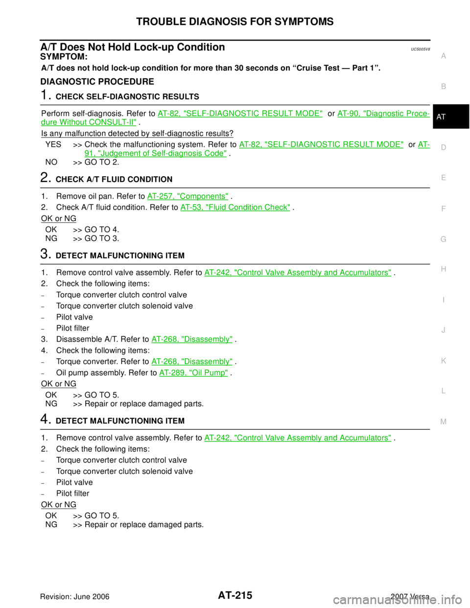
A/T Does Not Hold Lock-up ConditionUCS005V8
SYMPTOM:
A/T does not hold lock-up condition for more than 30 seconds on “Cruise Test — Part 1”.
DIAGNOSTIC PROCEDURE
1. CHECK SELF-DIAGNOSTIC RESULTS
Perform self-diagnosis. Refer to AT-82, "
SELF-DIAGNOSTIC RESULT MODE" or AT-90, "Diagnostic Proce-
dure Without CONSULT-II" .
Is any malfunction detected by self-diagnostic results?
YES >> Check the malfunctioning system. Refer to AT- 8 2 , "SELF-DIAGNOSTIC RESULT MODE" or AT-
91, "Judgement of Self-diagnosis Code" .
NO >> GO TO 2.
2. CHECK A/T FLUID CONDITION
1. Remove oil pan. Refer to AT-257, "
Components" .
2. Check A/T fluid condition. Refer to AT-53, "
Fluid Condition Check" .
OK or NG
OK >> GO TO 4.
NG >> GO TO 3.
3. DETECT MALFUNCTIONING ITEM
1. Remove control valve assembly. Refer to AT-242, "
Control Valve Assembly and Accumulators" .
2. Check the following items:
–Torque converter clutch control valve
–Torque converter clutch solenoid valve
–Pilot valve
–Pilot filter
3. Disassemble A/T. Refer to AT- 2 6 8 , "
Disassembly" .
4. Check the following items:
–Torque converter. Refer to AT- 2 6 8 , "Disassembly" .
–Oil pump assembly. Refer to AT-289, "Oil Pump" .
OK or NG
OK >> GO TO 5.
NG >> Repair or replace damaged parts.
4. DETECT MALFUNCTIONING ITEM
1. Remove control valve assembly. Refer to AT-242, "
Control Valve Assembly and Accumulators" .
2. Check the following items:
–Torque converter clutch control valve
–Torque converter clutch solenoid valve
–Pilot valve
–Pilot filter
OK or NG
OK >> GO TO 5.
NG >> Repair or replace damaged parts.
Page 306 of 2896
REPAIR FOR COMPONENT PARTS
AT-293
D
E
F
G
H
I
J
K
L
MA
B
AT
Revision: June 20062007 Versa
Control Valve AssemblyUCS005W 5
COMPONENTS
1. Pilot filter 2. Control valve upper body 3. Steel ball
4. Separating plate 5. Control valve inter body 6. Steel ball
7. Support plate 8. Separating plate 9. Control valve lower body
10. Line pressure relief valve spring 11. Check ball 12. Torque converter pressure holding
spring
13. Solenoid valve assembly 14. Terminal body 15. O-ring
16. O-ring 17. O-ring 18. Oil strainer
Refer to GI section to make sure icons (symbol marks) in the figure. Refer to GI-10, "
Components" .
SCIA5967J
Page 309 of 2896
AT-296
REPAIR FOR COMPONENT PARTS
Revision: June 20062007 Versa
9. Remove control valve inter body from control valve upper body.
10. Remove pilot filter (1) from control valve upper body (2).
11. Remove separating plate from control valve upper body (2).
12. Check to see that steel balls are properly positioned in control
valve inter body and then remove them.
CAUTION:
Be careful not to lose steel balls.
13. Check to see that steel balls are properly positioned in control
valve upper body and then remove them.
CAUTION:
Be careful not to lose steel balls.
SCIA4977E
SCIA7 011 E
SAT8 7 0J
SAT8 7 1J
Page 312 of 2896
REPAIR FOR COMPONENT PARTS
AT-299
D
E
F
G
H
I
J
K
L
MA
B
AT
Revision: June 20062007 Versa
c. Install pilot filter (1) on control valve upper body (2).
d. Place control valve inter body as shown in figure (side of control
valve lower body face up). Install steel balls in their proper posi-
tions.
e. Install control valve inter body (1) on control valve upper body
(2) using reamer bolts (F) as guides.
CAUTION:
Be careful not to dislocate or drop steel balls.
f. Install check balls (1), line pressure relief valve springs (2) and
torque converter pressure holding spring (3) in their proper posi-
tions in control valve lower body (4).
g. Install bolts (E) from bottom of control valve lower body (1).
Using bolts (E) as guides, install separating plate (2) as a set.
h. Install support plates (3) on control valve lower body (1).
SCIA7 011 E
SAT8 7 0J
SCIA7012E
SCIA6491J
SCIA7013E
Page 916 of 2896

CVT FLUID
CVT-19
D
E
F
G
H
I
J
K
L
MA
B
CVT
Revision: June 20062007 Versa
CVT FLUID COOLER DIAGNOSIS PROCEDURE
NOTE:
Insufficient cleaning of the cooler inlet hose exterior may lead to inaccurate debris identification.
1. Position an oil pan under the transaxle's inlet and outlet cooler hoses.
2. Clean the exterior and tip of the cooler inlet hose.
3. Insert the extension adapter hose of a can of Transmission
Cooler Cleaner (Nissan P/N 999MP-AM006) into the cooler out-
let hose.
CAUTION:
�Wear safety glasses and rubber gloves when spraying
the Transmission Cooler Cleaner.
�Spray Transmission Cooler Cleaner only with adequate
ventilation.
�Avoid contact with eyes and skin.
�Do not breath vapors or spray mist.
4. Hold the hose and can as high as possible and spray Transmis-
sion Cooler Cleaner in a continuous stream into the cooler outlet hose until CVT fluid flows out of the
cooler inlet hose for 5 seconds.
5. Tie a common white, basket-type coffee filter to the end of the
cooler inlet hose.
6. Insert the tip of an air gun into the end of the cooler outlet hose.
7. Wrap a shop rag around the air gun tip and end of cooler outlet
hose.
8. Blow compressed air regulated to 5 to 9 kg/cm
2 (70 to 130 psi)
through the cooler outlet hose to force any remaining CVT fluid
into the coffee filter.
9. Remove the coffee filter from the end of the cooler inlet hose.
10. Perform CVT-20, "
CVT FLUID COOLER INSPECTION PROCE-
DURE" .
SCIA4421E
SCIA4424E
SCIA4425E