Page 1019 of 2896

CVT-122
DTC P0776 PRESSURE CONTROL SOLENOID B PERFORMANCE (SEC PRES-
SURE SOLENOID VALVE)
Revision: June 20062007 Versa
Diagnostic ProcedureUCS00616
1. CHECK INPUT SIGNAL
With CONSULT-II
1. Start engine.
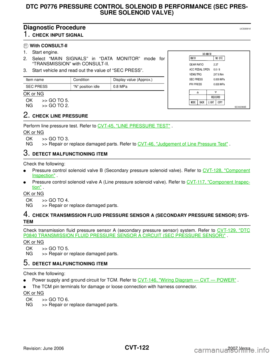
2. Select “MAIN SIGNALS” in “DATA MONITOR” mode for
“TRANSMISSION” with CONSULT-II.
3. Start vehicle and read out the value of “SEC PRESS”.
OK or NG
OK >> GO TO 5.
NG >> GO TO 2.
2. CHECK LINE PRESSURE
Perform line pressure test. Refer to CVT-45, "
LINE PRESSURE TEST" .
OK or NG
OK >> GO TO 3.
NG >> Repair or replace damaged parts. Refer to CVT-46, "
Judgement of Line Pressure Test" .
3. DETECT MALFUNCTIONING ITEM
Check the following:
�Pressure control solenoid valve B (Secondary pressure solenoid valve). Refer to CVT-128, "Component
Inspection" .
�Pressure control solenoid valve A (Line pressure solenoid valve). Refer to CVT-117, "Component Inspec-
tion" .
OK or NG
OK >> GO TO 4.
NG >> Repair or replace damaged parts.
4. CHECK TRANSMISSION FLUID PRESSURE SENSOR A (SECONDARY PRESSURE SENSOR) SYS-
TEM
Check transmission fluid pressure sensor A (secondary pressure sensor) system. Refer to CVT-129, "
DTC
P0840 TRANSMISSION FLUID PRESSURE SENSOR A CIRCUIT (SEC PRESSURE SENSOR)" .
OK or NG
OK >> GO TO 5.
NG >> Repair or replace damaged parts.
5. DETECT MALFUNCTIONING ITEM
Check the following:
�Power supply and ground circuit for TCM. Refer to CVT-146, "Wiring Diagram — CVT — POWER" .
�The TCM pin terminals for damage or loose connection with harness connector.
OK or NG
OK >> GO TO 6.
NG >> Repair or replace damaged parts.
Item name Condition Display value (Approx.)
SEC PRESS “N” position idle 0.8 MPa
SCIA2366E
Page 1022 of 2896
DTC P0778 PRESSURE CONTROL SOLENOID B ELECTRICAL (SEC PRES-
SURE SOLENOID VALVE)
CVT-125
D
E
F
G
H
I
J
K
L
MA
B
CVT
Revision: June 20062007 Versa
Wiring Diagram — CVT — SECPSVUCS0061C
BCWA0676E
Page 1027 of 2896
CVT-130
DTC P0840 TRANSMISSION FLUID PRESSURE SENSOR A CIRCUIT (SEC
PRESSURE SENSOR)
Revision: June 20062007 Versa
Wiring Diagram — CVT — SECPSUCS0061S
BCWA0677E
Page 1035 of 2896
CVT-138
DTC P0845 TRANSMISSION FLUID PRESSURE SENSOR B CIRCUIT (PRI
PRESSURE SENSOR)
Revision: June 20062007 Versa
Wiring Diagram — CVT — PRIPSUCS00625
BCWA0678E
Page 1040 of 2896

DTC P0868 SECONDARY PRESSURE DOWN
CVT-143
D
E
F
G
H
I
J
K
L
MA
B
CVT
Revision: June 20062007 Versa
Diagnostic ProcedureUCS0062C
1. CHECK INPUT SIGNAL
With CONSULT-II
1. Start engine.
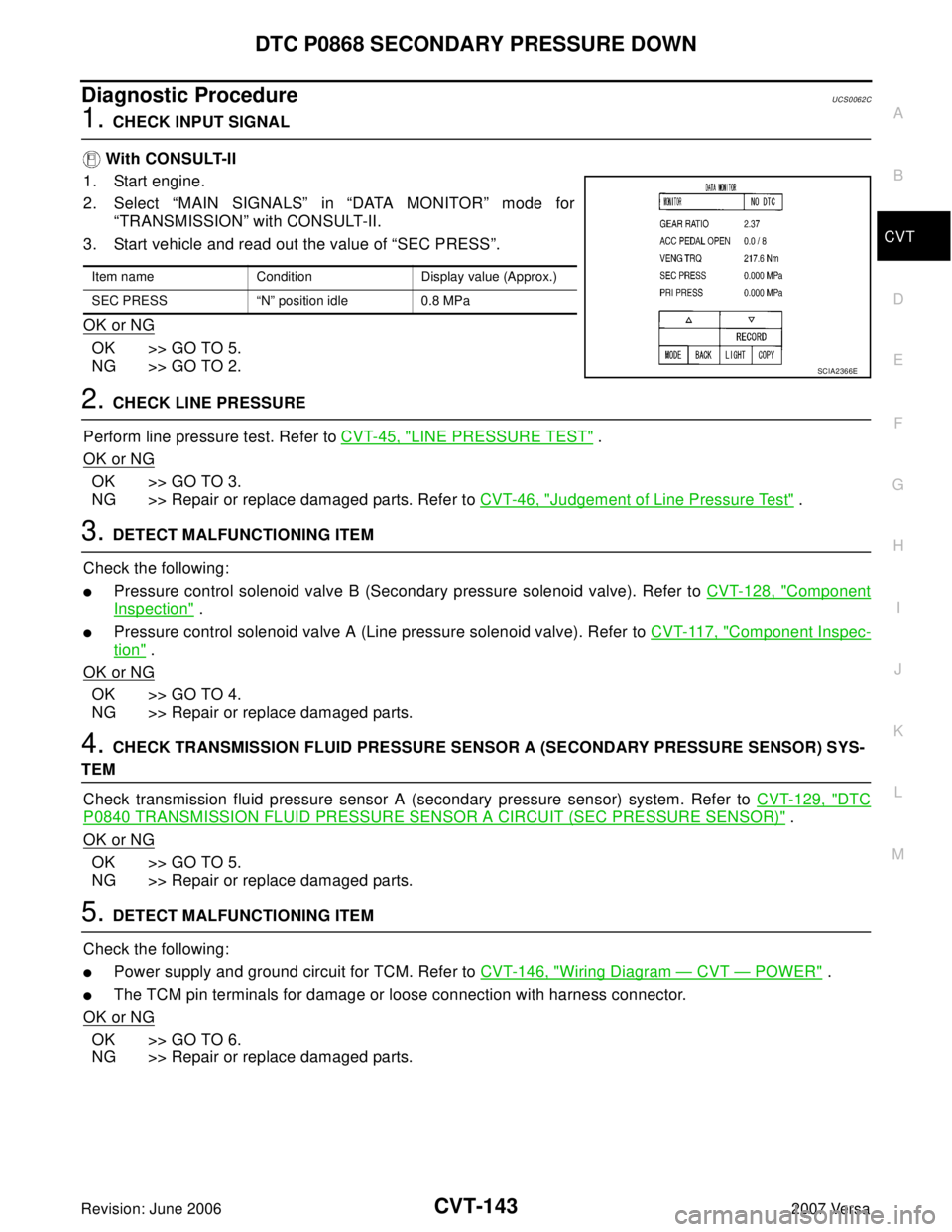
2. Select “MAIN SIGNALS” in “DATA MONITOR” mode for
“TRANSMISSION” with CONSULT-II.
3. Start vehicle and read out the value of “SEC PRESS”.
OK or NG
OK >> GO TO 5.
NG >> GO TO 2.
2. CHECK LINE PRESSURE
Perform line pressure test. Refer to CVT-45, "
LINE PRESSURE TEST" .
OK or NG
OK >> GO TO 3.
NG >> Repair or replace damaged parts. Refer to CVT-46, "
Judgement of Line Pressure Test" .
3. DETECT MALFUNCTIONING ITEM
Check the following:
�Pressure control solenoid valve B (Secondary pressure solenoid valve). Refer to CVT-128, "Component
Inspection" .
�Pressure control solenoid valve A (Line pressure solenoid valve). Refer to CVT-117, "Component Inspec-
tion" .
OK or NG
OK >> GO TO 4.
NG >> Repair or replace damaged parts.
4. CHECK TRANSMISSION FLUID PRESSURE SENSOR A (SECONDARY PRESSURE SENSOR) SYS-
TEM
Check transmission fluid pressure sensor A (secondary pressure sensor) system. Refer to CVT-129, "
DTC
P0840 TRANSMISSION FLUID PRESSURE SENSOR A CIRCUIT (SEC PRESSURE SENSOR)" .
OK or NG
OK >> GO TO 5.
NG >> Repair or replace damaged parts.
5. DETECT MALFUNCTIONING ITEM
Check the following:
�Power supply and ground circuit for TCM. Refer to CVT-146, "Wiring Diagram — CVT — POWER" .
�The TCM pin terminals for damage or loose connection with harness connector.
OK or NG
OK >> GO TO 6.
NG >> Repair or replace damaged parts.
Item name Condition Display value (Approx.)
SEC PRESS “N” position idle 0.8 MPa
SCIA2366E
Page 1043 of 2896
CVT-146
DTC P1701 TRANSMISSION CONTROL MODULE (POWER SUPPLY)
Revision: June 20062007 Versa
Wiring Diagram — CVT — POWERUCS0062H
BCWA0679E
Page 1056 of 2896
DTC P1740 LOCK-UP SELECT SOLENOID VALVE CIRCUIT
CVT-159
D
E
F
G
H
I
J
K
L
MA
B
CVT
Revision: June 20062007 Versa
Wiring Diagram — CVT — L/USSVUCS0063A
BCWA0680E
Page 1062 of 2896
DTC P1777 STEP MOTOR - CIRCUIT
CVT-165
D
E
F
G
H
I
J
K
L
MA
B
CVT
Revision: June 20062007 Versa
Wiring Diagram — CVT — STMUCS0063N
BCWA0681E