Page 993 of 1226

Checking Cooling System
CHECKING HOSES AND CLAMPS
Check hoses and clamps for proper attachment, leaks, cracks,
damage, loose connections, cha®ng and deterioration.
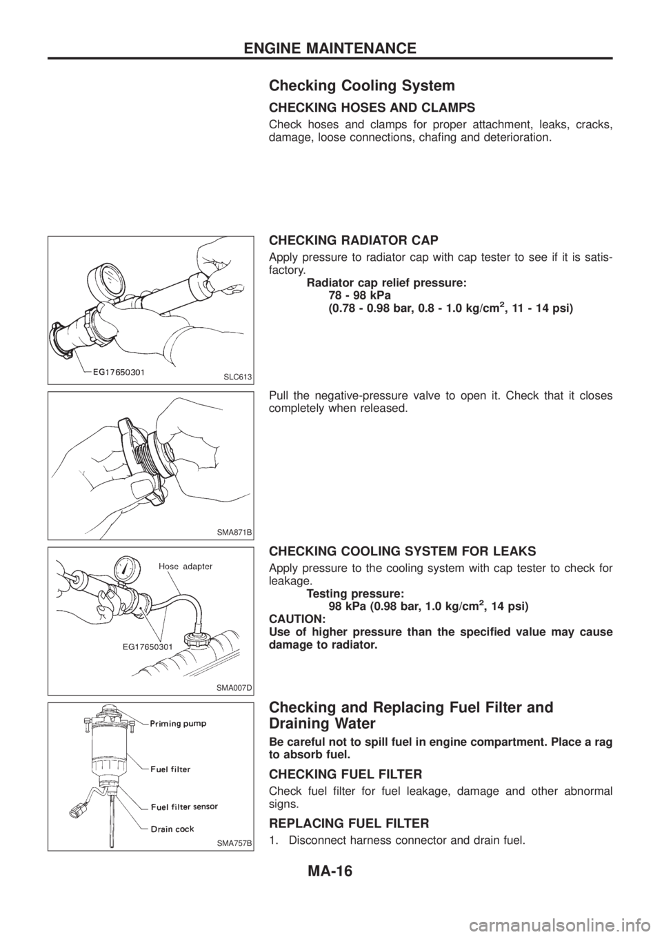
CHECKING RADIATOR CAP
Apply pressure to radiator cap with cap tester to see if it is satis-
factory.
Radiator cap relief pressure:
78-98kPa
(0.78 - 0.98 bar, 0.8 - 1.0 kg/cm
2, 11 - 14 psi)
Pull the negative-pressure valve to open it. Check that it closes
completely when released.
CHECKING COOLING SYSTEM FOR LEAKS
Apply pressure to the cooling system with cap tester to check for
leakage.
Testing pressure:
98 kPa (0.98 bar, 1.0 kg/cm
2, 14 psi)
CAUTION:
Use of higher pressure than the speci®ed value may cause
damage to radiator.
Checking and Replacing Fuel Filter and
Draining Water
Be careful not to spill fuel in engine compartment. Place a rag
to absorb fuel.
CHECKING FUEL FILTER
Check fuel ®lter for fuel leakage, damage and other abnormal
signs.
REPLACING FUEL FILTER
1. Disconnect harness connector and drain fuel.
SLC613
SMA871B
SMA007D
SMA757B
ENGINE MAINTENANCE
MA-16
Page 1053 of 1226
Removal
+Remove propeller shaft.
+Remove drive shaft. Refer to FA section (``FRONT AXLE Ð
Knuckle Flange'').
+Remove axle shaft.
Refer to RA section (``REAR AXLE'').
+Remove front and rear ®nal drive mounting bolts.
CAUTION:
+Be careful not to damage spline, sleeve yoke and front oil
seal when removing propeller shaft.
+Before removing the ®nal drive assembly or rear axle
assembly, disconnect the ABS sensor harness connector
from the assembly and move it away from the ®nal drive/
rear axle assembly area. Failure to do so may result in the
sensor wires being damaged and the sensor becoming
inoperative.
Installation
+Fill ®nal drive with recommended gear oil.
+Pay attention to the direction of gasket.
SPD103
SPD123
SPD767
REMOVAL AND INSTALLATION
PD-11
Page 1069 of 1226
To avoid confusion while calculating bearing shims, it is absolutely
necessary to stay with the metric system. If you measure anything
in inches,the results must be converted to the metric system.
Drive Pinion Height
1. First prepare Tools for pinion height adjustment.
:
V1Heightgauge(ST31251000)*
V2Dummyshaft(ST31181001)*
V3SpacerKV38108700 [thickness: 2.00mm (0.0787 in)]*
V4Feelergauge (commercial servcie tool)
2. To simplify the job, make a chart, like the one below, to orga- nize your calculations.
LETTERS HUNDREDTHS OF
A MILLIMETER
H: Head number
D ¢: Figure marked on dummy shaft
S: Figure marked on height gauge
N:Measuringclearance
* Set tools are available: ST3125S000 (tools 1 and 2) ST3125S001 (tools 1, 2 and 3)
3. Write the following numbers down the chart.H: Head number
D¢: Figure marked on dummy shaft.
SPD758
SPD542
SPD759
ADJUSTMENT
PD-27
Page 1096 of 1226

REAR AXLE &
REAR SUSPENSION
SECTION
RA
CONTENTS
PRECAUTIONS AND PREPARATION............................1
Precautions ..................................................................1
Special Service Tools ..................................................1
Commercial Service Tools ...........................................2
NOISE, VIBRATION AND HARSHNESS (NVH)
TROUBLESHOOTING.....................................................3
NVH Troubleshooting Chart.........................................3
REAR AXLE AND REAR SUSPENSION........................4
ON-VEHICLE SERVICE..................................................5
Rear Axle and Rear Suspension Parts .......................5
Rear Wheel Bearing ....................................................5
REAR AXLE.....................................................................6
Components.................................................................6
Removal .......................................................................7
Inspection.....................................................................9Installation ....................................................................9
REAR SUSPENSION.....................................................12
Removal and Installation ...........................................13
Coil Spring and Shock Absorber ...............................14
Upper Link, Lower Link and Panhard Rod ................14
Stabilizer Bar .............................................................15
STABILIZER RELEASE DEVICE..................................16
System Components .................................................16
System Description ....................................................16
Removal and Installation ...........................................17
Wiring Diagram ..........................................................18
Trouble Diagnoses.....................................................20
SERVICE DATA AND SPECIFICATIONS (SDS)..........25
General Speci®cations ...............................................25
Inspection and Adjustment ........................................25
RA
Page 1099 of 1226

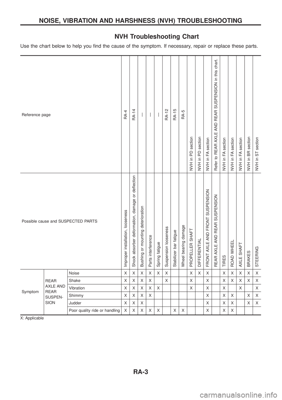
NVH Troubleshooting Chart
Use the chart below to help you ®nd the cause of the symptom. If necessary, repair or replace these parts.
Reference pageRA-4
RA-14
Ð
Ð
Ð
RA-12
RA-15
RA-5
NVH in PD section
NVH in PD section
NVH in FA section
Refer to REAR AXLE AND REAR SUSPENSION in this chart.
NVH in FA section
NVH in FA section
NVH in FA section
NVH in BR section
NVH in ST section
Possible cause and SUSPECTED PARTS
Improper installation, looseness
Shock absorber deformation, damage or de¯ection
Bushing or mounting deterioration
Parts interference
Spring fatigue
Suspension looseness
Stabilizer bar fatigue
Wheel bearing damage
PROPELLER SHAFT
DIFFERENTIAL
FRONT AXLE AND FRONT SUSPENSION
REAR AXLE AND REAR SUSPENSION
TIRES
ROAD WHEEL
AXLE SHAFT
BRAKES
STEERING
SymptomREAR
AXLE AND
REAR
SUSPEN-
SIONNoiseXXXXXX XXX XXXXX
ShakeXXXX X X X XXXXX
VibrationXXXXXXXXXX
ShimmyXXXX X XX XX
Judder X X X X X X X X
Poor quality ride or handlingXXXXX XX X XX
X: Applicable
NOISE, VIBRATION AND HARSHNESS (NVH) TROUBLESHOOTING
RA-3
Page 1101 of 1226
Rear Axle and Rear Suspension Parts
Check rear axle and rear suspension parts for excessive play, wear
or damage.
+Shake each rear wheel to check for excessive play.
+Retighten all nuts and bolts to the speci®ed torque.
Tightening torque:
Refer to REAR SUSPENSION, RA-12.
+Check shock absorber for oil leakage or other damage.
+Check shock absorber bushing for excessive wear or other
damage.
Rear Wheel Bearing
+Check that wheel bearings operate smoothly.
+Check axial end play.
Axial end play:
0mm(0in)
SMA525A
SRA814A
SRA755A
ON-VEHICLE SERVICE
RA-5
Page 1103 of 1226
Removal
CAUTION:
+Before removing the rear axle, disconnect the ABS wheel
sensor from the assembly. Then move it away from the
axle. Failure to do so may result in damage to the sensor
wires and the sensor becoming inoperative.
+Wheel bearing does not require maintenance.
+If growling noise is emitted from wheel bearing during
operation, replace wheel bearing assembly.
+If the wheel bearing assembly is removed, it must be renewed.
The old assembly must not be re-used.
1. Disconnect parking brake cable and brake tube.
2. Remove nuts securing wheel bearing cage with baffle plate.
3. Draw out axle shaft with Tool.
When drawing out axle shaft, be careful not to damage oil seal.
4. Remove O-ring.
5. Remove oil seal with a screwdriver.
Do not reuse oil seal once it is removed.
Always install new one.
6. Remove ABS sensor rotor. Ð Models with ABS Ð
SRA757A
SRA845A
SRA846A
SRA799A
REAR AXLE
RA-7
Page 1106 of 1226
6. Install a new wheel bearing lock washer.
7. Tighten wheel bearing lock nut to speci®ed torque.
: 441 - 490 Nzm (45 - 50 kg-m, 325 - 362 ft-lb)
Be sure to bend bearing lock washer up.
8. Check wheel bearing preload.
a. Turn bearing cage (with respect to axle shaft) two or three
times. It must turn smoothly.
b. Attach spring gauge to bearing cage bolt (as shown at left) and
pull it at a speed of 10 rpm to measure preload.
Spring gauge indication:
8.8 - 42.2 N (0.9 - 4.3 kg, 2.0 - 9.5 lb)
9. Install new oil seal to rear axle housing using a suitable tool.
After installing new oil seal, coat sealing lip with multi-purpose
grease.
10. Install new O-ring to rear axle housing.
11. Press ABS sensor rotor onto axle shaft until it contacts wheel
bearing lock nut.
12. Install axle shafts in rear axle housing.
Be careful not to damage oil seal.
SRA828A
SRA821A
SRA850A
SRA822A
SRA823A
REAR AXLE
Installation (Cont'd)
RA-10