Page 1012 of 1226
Removal
1. Remove front and rear propeller shafts. Refer to PD section
(``Removal and Installation'', ``PROPELLER SHAFT'').
2. Remove clutch operating cylinder.
3. Remove exhaust front and rear tubes. Refer to FE section
(``EXHAUST SYSTEM'').
4. Disconnect vehicle speed sensor, back-up lamp switch, 4WD
switch and neutral position switch harness connector.
5. Remove center brake cable. Refer to BR section.
6. Remove shift lever of transmission. Refer to MT-12 (RS5R30A).
7. Remove transfer control lever. Refer to TF section (``Removal'',
``REMOVAL AND INSTALLATION'').
8. Support engine by placing a jack under oil pan.
+Do not place jack under the oil pan drain plug.
9. Remove transmission with transfer from engine.
WARNING:
Support Manual Transmission with transfer, while removing it.
SMT321D
REMOVAL AND INSTALLATION
MT-5
Page 1053 of 1226
Removal
+Remove propeller shaft.
+Remove drive shaft. Refer to FA section (``FRONT AXLE Ð
Knuckle Flange'').
+Remove axle shaft.
Refer to RA section (``REAR AXLE'').
+Remove front and rear ®nal drive mounting bolts.
CAUTION:
+Be careful not to damage spline, sleeve yoke and front oil
seal when removing propeller shaft.
+Before removing the ®nal drive assembly or rear axle
assembly, disconnect the ABS sensor harness connector
from the assembly and move it away from the ®nal drive/
rear axle assembly area. Failure to do so may result in the
sensor wires being damaged and the sensor becoming
inoperative.
Installation
+Fill ®nal drive with recommended gear oil.
+Pay attention to the direction of gasket.
SPD103
SPD123
SPD767
REMOVAL AND INSTALLATION
PD-11
Page 1091 of 1226
Electrical Components Inspection
DIFFERENTIAL LOCK INDICATOR SWITCH CHECK
+Check switch function by checking continuity.
Continuity:
ON Continuity should exist.
OFF Continuity should not exist.
If NG, replace differential lock indicator switch.
DIFFERENTIAL LOCK SOLENOID CHECK
1. Disconnect differential lock solenoid 4-pin connector.
2. Check continuity between terminals
V1andV3,V2andV4.
Continuity should exist.
If NG, replace differential lock solenoid.
SPEED SENSOR CHECK
Refer to EL section.
SPD443A
SPD444A
DIFFERENTIAL LOCK
PD-49
Page 1092 of 1226

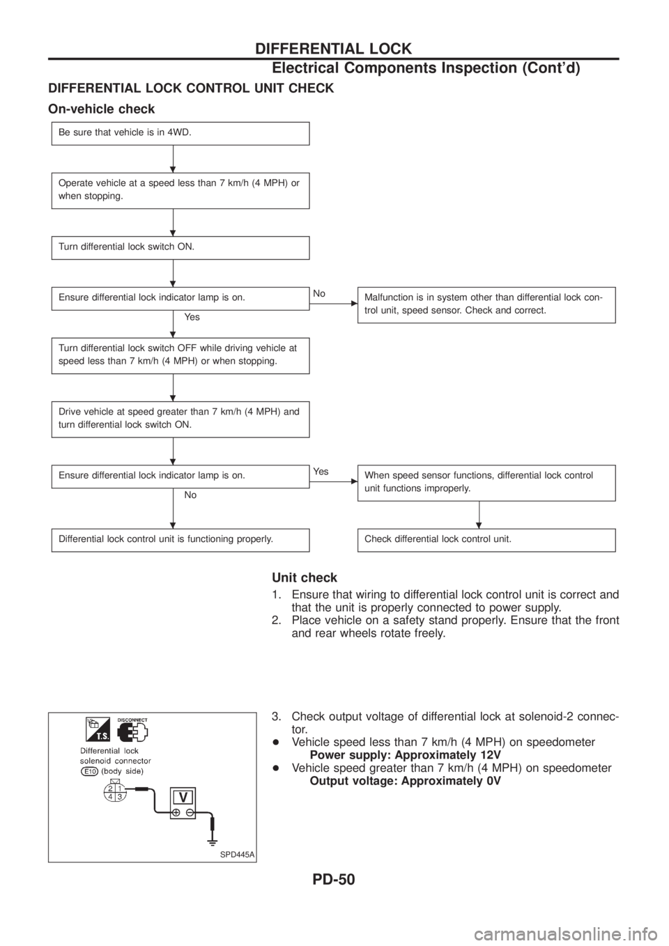
DIFFERENTIAL LOCK CONTROL UNIT CHECK
On-vehicle check
Be sure that vehicle is in 4WD.
Operate vehicle at a speed less than 7 km/h (4 MPH) or
when stopping.
Turn differential lock switch ON.
Ensure differential lock indicator lamp is on.
Ye s
cNo
Malfunction is in system other than differential lock con-
trol unit, speed sensor. Check and correct.
Turn differential lock switch OFF while driving vehicle at
speed less than 7 km/h (4 MPH) or when stopping.
Drive vehicle at speed greater than 7 km/h (4 MPH) and
turn differential lock switch ON.
Ensure differential lock indicator lamp is on.
No
cYe s
When speed sensor functions, differential lock control
unit functions improperly.
Differential lock control unit is functioning properly.Check differential lock control unit.
Unit check
1. Ensure that wiring to differential lock control unit is correct and
that the unit is properly connected to power supply.
2. Place vehicle on a safety stand properly. Ensure that the front
and rear wheels rotate freely.
3. Check output voltage of differential lock at solenoid-2 connec-
tor.
+Vehicle speed less than 7 km/h (4 MPH) on speedometer
Power supply: Approximately 12V
+Vehicle speed greater than 7 km/h (4 MPH) on speedometer
Output voltage: Approximately 0V
SPD445A
.
.
.
.
.
.
..
DIFFERENTIAL LOCK
Electrical Components Inspection (Cont'd)
PD-50
Page 1103 of 1226
Removal
CAUTION:
+Before removing the rear axle, disconnect the ABS wheel
sensor from the assembly. Then move it away from the
axle. Failure to do so may result in damage to the sensor
wires and the sensor becoming inoperative.
+Wheel bearing does not require maintenance.
+If growling noise is emitted from wheel bearing during
operation, replace wheel bearing assembly.
+If the wheel bearing assembly is removed, it must be renewed.
The old assembly must not be re-used.
1. Disconnect parking brake cable and brake tube.
2. Remove nuts securing wheel bearing cage with baffle plate.
3. Draw out axle shaft with Tool.
When drawing out axle shaft, be careful not to damage oil seal.
4. Remove O-ring.
5. Remove oil seal with a screwdriver.
Do not reuse oil seal once it is removed.
Always install new one.
6. Remove ABS sensor rotor. Ð Models with ABS Ð
SRA757A
SRA845A
SRA846A
SRA799A
REAR AXLE
RA-7
Page 1106 of 1226
6. Install a new wheel bearing lock washer.
7. Tighten wheel bearing lock nut to speci®ed torque.
: 441 - 490 Nzm (45 - 50 kg-m, 325 - 362 ft-lb)
Be sure to bend bearing lock washer up.
8. Check wheel bearing preload.
a. Turn bearing cage (with respect to axle shaft) two or three
times. It must turn smoothly.
b. Attach spring gauge to bearing cage bolt (as shown at left) and
pull it at a speed of 10 rpm to measure preload.
Spring gauge indication:
8.8 - 42.2 N (0.9 - 4.3 kg, 2.0 - 9.5 lb)
9. Install new oil seal to rear axle housing using a suitable tool.
After installing new oil seal, coat sealing lip with multi-purpose
grease.
10. Install new O-ring to rear axle housing.
11. Press ABS sensor rotor onto axle shaft until it contacts wheel
bearing lock nut.
12. Install axle shafts in rear axle housing.
Be careful not to damage oil seal.
SRA828A
SRA821A
SRA850A
SRA822A
SRA823A
REAR AXLE
Installation (Cont'd)
RA-10
Page 1109 of 1226
Removal and Installation
+Support axle and suspension components with a suitable jack
and block.
+Disconnect brake hydraulic line and parking brake cables at
back plates.
CAUTION:
+Use ¯are nut wrench when removing or installing brake
tubes.
+Before removing the rear suspension assembly, discon-
nect the ABS wheel sensor from the assembly. Then move
it away from the rear suspension assembly. Failure to do
so may result in damage to the sensor wires and the sen-
sor becoming inoperative.
+Remove stabilizer bar from body.
+Remove upper links and lower links from body.
+Remove panhard rod from body.
+Disconnect rear end of propeller shaft. Refer to PD section.
+Remove upper end nuts of shock absorber.
SRA825A
SBR820BA
REAR SUSPENSION
RA-13
Page 1112 of 1226

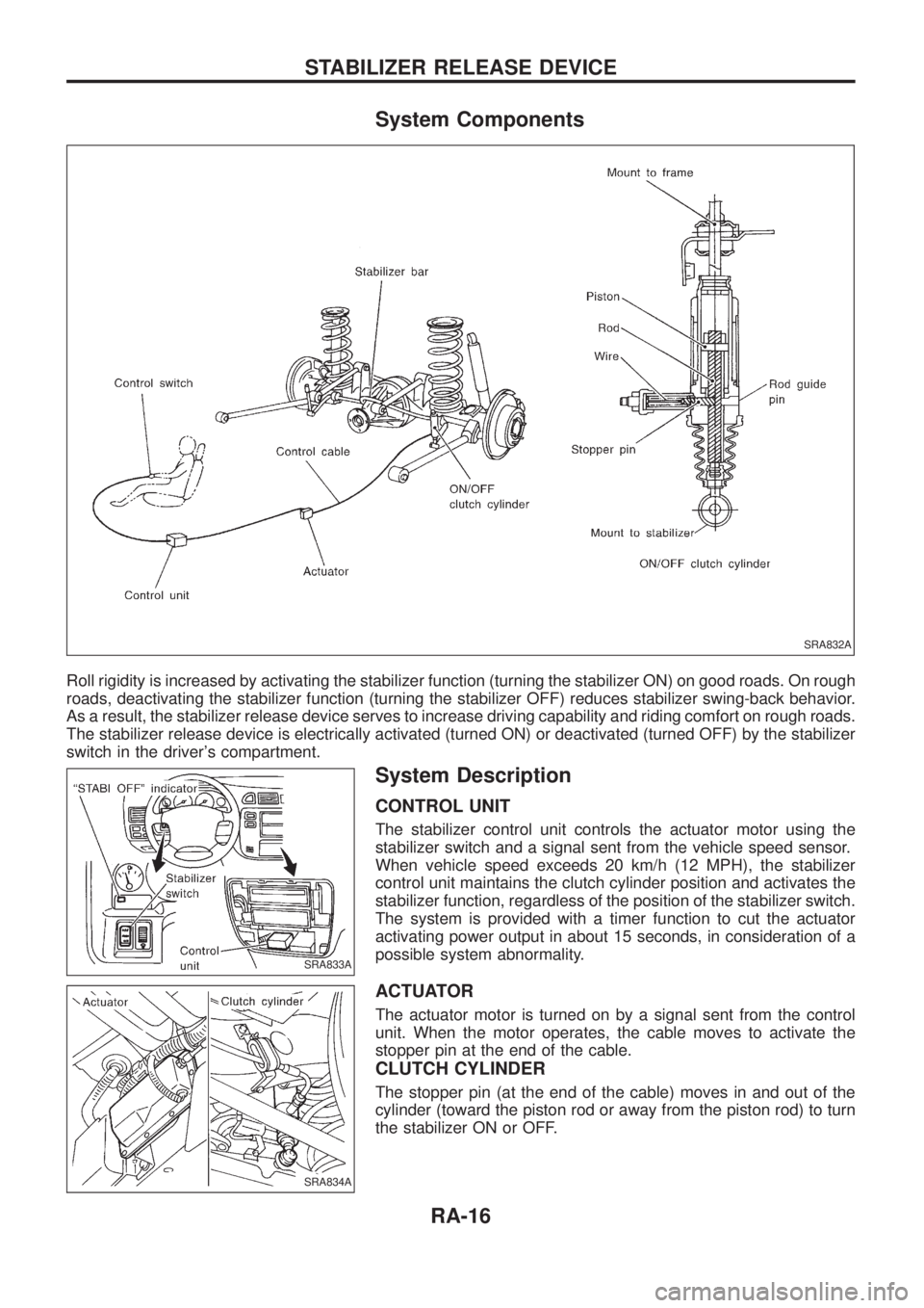
System Components
Roll rigidity is increased by activating the stabilizer function (turning the stabilizer ON) on good roads. On rough
roads, deactivating the stabilizer function (turning the stabilizer OFF) reduces stabilizer swing-back behavior.
As a result, the stabilizer release device serves to increase driving capability and riding comfort on rough roads.
The stabilizer release device is electrically activated (turned ON) or deactivated (turned OFF) by the stabilizer
switch in the driver's compartment.
System Description
CONTROL UNIT
The stabilizer control unit controls the actuator motor using the
stabilizer switch and a signal sent from the vehicle speed sensor.
When vehicle speed exceeds 20 km/h (12 MPH), the stabilizer
control unit maintains the clutch cylinder position and activates the
stabilizer function, regardless of the position of the stabilizer switch.
The system is provided with a timer function to cut the actuator
activating power output in about 15 seconds, in consideration of a
possible system abnormality.
ACTUATOR
The actuator motor is turned on by a signal sent from the control
unit. When the motor operates, the cable moves to activate the
stopper pin at the end of the cable.
CLUTCH CYLINDER
The stopper pin (at the end of the cable) moves in and out of the
cylinder (toward the piston rod or away from the piston rod) to turn
the stabilizer ON or OFF.
SRA832A
SRA833A
SRA834A
STABILIZER RELEASE DEVICE
RA-16