2006 NISSAN PATROL display
[x] Cancel search: displayPage 196 of 1226
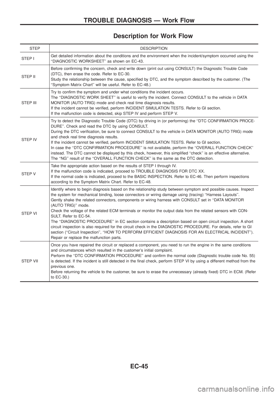
Description for Work Flow
STEP DESCRIPTION
STEP IGet detailed information about the conditions and the environment when the incident/symptom occurred using the
``DIAGNOSTIC WORKSHEET'' as shown on EC-43.
STEP IIBefore con®rming the concern, check and write down (print out using CONSULT) the Diagnostic Trouble Code
(DTC), then erase the code. Refer to EC-30.
Study the relationship between the cause, speci®ed by DTC, and the symptom described by the customer. (The
``Symptom Matrix Chart'' will be useful. Refer to EC-48.)
STEP IIITry to con®rm the symptom and under what conditions the incident occurs.
The ``DIAGNOSTIC WORK SHEET'' is useful to verify the incident. Connect CONSULT to the vehicle in DATA
MONITOR (AUTO TRIG) mode and check real time diagnosis results.
If the incident cannot be veri®ed, perform INCIDENT SIMULATION TESTS. Refer to GI section.
If the malfunction code is detected, skip STEP IV and perform STEP V.
STEP IVTry to detect the Diagnostic Trouble Code (DTC) by driving in (or performing) the ``DTC CONFIRMATION PROCE-
DURE''. Check and read the DTC by using CONSULT.
During the DTC veri®cation, be sure to connect CONSULT to the vehicle in DATA MONITOR (AUTO TRIG) mode
and check real time diagnosis results.
If the incident cannot be veri®ed, perform INCIDENT SIMULATION TESTS. Refer to GI section.
In case the ``DTC CONFIRMATION PROCEDURE'' is not available, perform the ``OVERALL FUNCTION CHECK''
instead. The DTC cannot be displayed by this check, however, this simpli®ed ``check'' is an effective alternative.
The ``NG'' result of the ``OVERALL FUNCTION CHECK'' is the same as the DTC detection.
STEP VTake the appropriate action based on the results of STEP I through IV.
If the malfunction code is indicated, proceed to TROUBLE DIAGNOSIS FOR DTC XX.
If the normal code is indicated, proceed to the BASIC INSPECTION. Refer to EC-46. Then perform inspections
according to the Symptom Matrix Chart. Refer to EC-48.
STEP VIIdentify where to begin diagnosis based on the relationship study between symptom and possible causes. Inspect
the system for mechanical binding, loose connectors or wiring damage using (tracing) ``Harness Layouts''.
Gently shake the related connectors, components or wiring harness with CONSULT set in ``DATA MONITOR
(AUTO TRIG)'' mode.
Check the voltage of the related ECM terminals or monitor the output data from the related sensors with CON-
SULT. Refer to EC-54.
The ``DIAGNOSTIC PROCEDURE'' in EC section contains a description based on open circuit inspection. A short
circuit inspection is also required for the circuit check in the DIAGNOSTIC PROCEDURE. For details, refer to GI
section (``Circuit Inspection'', ``HOW TO PERFORM EFFICIENT DIAGNOSIS FOR AN ELECTRICAL INCIDENT'').
Repair or replace the malfunction parts.
STEP VIIOnce you have repaired the circuit or replaced a component, you need to run the engine in the same conditions
and circumstances which resulted in the customer's initial complaint.
Perform the ``DTC CONFIRMATION PROCEDURE'' and con®rm the normal code (Diagnostic trouble code No. 55)
is detected. If the incident is still detected in the ®nal check, perform STEP VI by using a different method from the
previous one.
Before returning the vehicle to the customer, be sure to erase the unnecessary (already ®xed) DTC in ECM. (Refer
to EC-30.)
TROUBLE DIAGNOSIS Ð Work Flow
EC-45
Page 198 of 1226
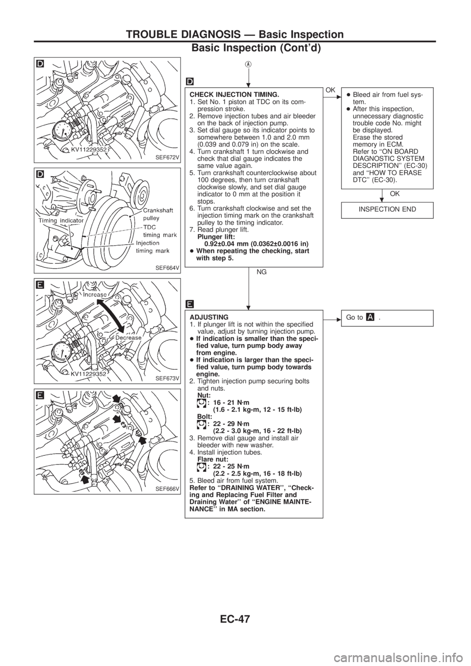
jA
CHECK INJECTION TIMING.
1. Set No. 1 piston at TDC on its com-
pression stroke.
2. Remove injection tubes and air bleeder
on the back of injection pump.
3. Set dial gauge so its indicator points to
somewhere between 1.0 and 2.0 mm
(0.039 and 0.079 in) on the scale.
4. Turn crankshaft 1 turn clockwise and
check that dial gauge indicates the
same value again.
5. Turn crankshaft counterclockwise about
100 degrees, then turn crankshaft
clockwise slowly, and set dial gauge
indicator to 0 mm at the position it
stops.
6. Turn crankshaft clockwise and set the
injection timing mark on the crankshaft
pulley to the timing indicator.
7. Read plunger lift.
Plunger lift:
0.92 0.04 mm (0.0362 0.0016 in)
+When repeating the checking, start
with step 5.
NG
cOK
+Bleed air from fuel sys-
tem.
+After this inspection,
unnecessary diagnostic
trouble code No. might
be displayed.
Erase the stored
memory in ECM.
Refer to ``ON BOARD
DIAGNOSTIC SYSTEM
DESCRIPTION'' (EC-30)
and ``HOW TO ERASE
DTC'' (EC-30).
OK
INSPECTION END
ADJUSTING
1. If plunger lift is not within the speci®ed
value, adjust by turning injection pump.
+If indication is smaller than the speci-
®ed value, turn pump body away
from engine.
+If indication is larger than the speci-
®ed value, turn pump body towards
engine.
2. Tighten injection pump securing bolts
and nuts.
Nut:
: 16-21Nzm
(1.6 - 2.1 kg-m, 12 - 15 ft-lb)
Bolt:
: 22-29Nzm
(2.2 - 3.0 kg-m, 16 - 22 ft-lb)
3. Remove dial gauge and install air
bleeder with new washer.
4. Install injection tubes.
Flare nut:
: 22-25Nzm
(2.2 - 2.5 kg-m, 16 - 18 ft-lb)
5. Bleed air from fuel system.
Refer to ``DRAINING WATER'', ``Check-
ing and Replacing Fuel Filter and
Draining Water'' of ``ENGINE MAINTE-
NANCE'' in MA section.
cGo to.
SEF672V
SEF664V
SEF673V
SEF666V
.
.
.
TROUBLE DIAGNOSIS Ð Basic Inspection
Basic Inspection (Cont'd)
EC-47
Page 249 of 1226
DIAGNOSTIC TROUBLE CODE CONFIRMATION
PROCEDURE
Note: If DTC 18, 22, 25 and DTC 15 are displayed, perform
TROUBLE DIAGNOSIS FOR DTC 15. (See EC-87.)
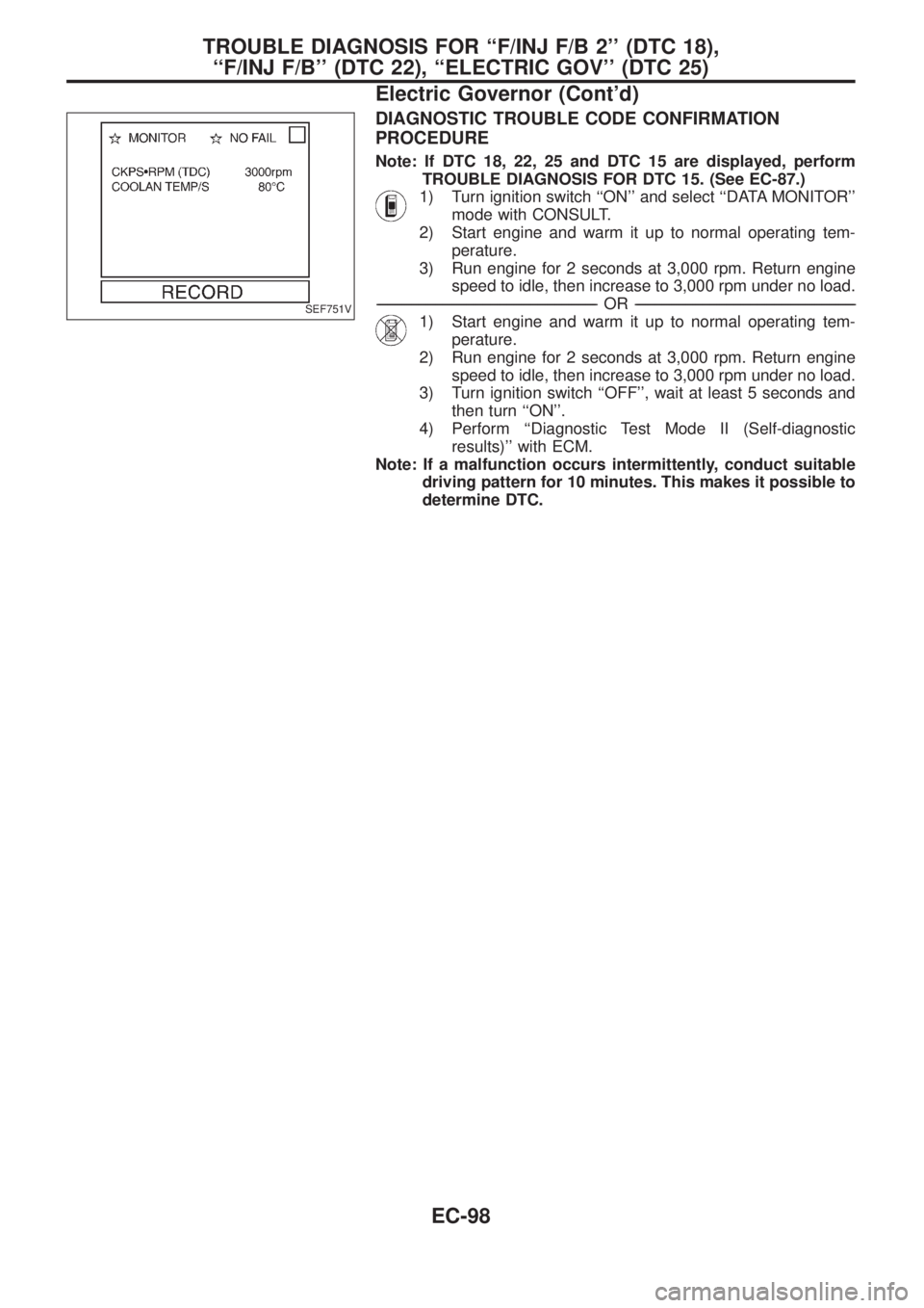
1) Turn ignition switch ``ON'' and select ``DATA MONITOR''
mode with CONSULT.
2) Start engine and warm it up to normal operating tem-
perature.
3) Run engine for 2 seconds at 3,000 rpm. Return engine
speed to idle, then increase to 3,000 rpm under no load.
-------------------------------------------------------------------------------------------------------------------------------------------------------------------------------------------------------------------------------------------------------OR-------------------------------------------------------------------------------------------------------------------------------------------------------------------------------------------------------------------------------------------------------
1) Start engine and warm it up to normal operating tem-
perature.
2) Run engine for 2 seconds at 3,000 rpm. Return engine
speed to idle, then increase to 3,000 rpm under no load.
3) Turn ignition switch ``OFF'', wait at least 5 seconds and
then turn ``ON''.
4) Perform ``Diagnostic Test Mode II (Self-diagnostic
results)'' with ECM.
Note: If a malfunction occurs intermittently, conduct suitable
driving pattern for 10 minutes. This makes it possible to
determine DTC.SEF751V
TROUBLE DIAGNOSIS FOR ``F/INJ F/B 2'' (DTC 18),
``F/INJ F/B'' (DTC 22), ``ELECTRIC GOV'' (DTC 25)
Electric Governor (Cont'd)
EC-98
Page 253 of 1226
ON BOARD DIAGNOSIS LOGIC
Diagnostic
Trouble Code
No.Malfunction is detected when ....Check Items
(Possible cause)
21+Injection timing feedback system does not operate
properly. (This system consists essentially of ECM,
injection timing control valve and needle lift sensor.)+Harness or connectors
[Injection timing control valve, needle lift sensor,
crankshaft position sensor (TDC) circuits]
+Injection timing control valve
+Needle lift sensor
+Crankshaft position sensor (TDC)
+Air in fuel line
DIAGNOSTIC TROUBLE CODE CONFIRMATION
PROCEDURE
Note: If both DTC 21 and 34 or 47 are displayed, perform
TROUBLE DIAGNOSIS FOR DTC 34 or 47. (See EC-126
or EC-144.)
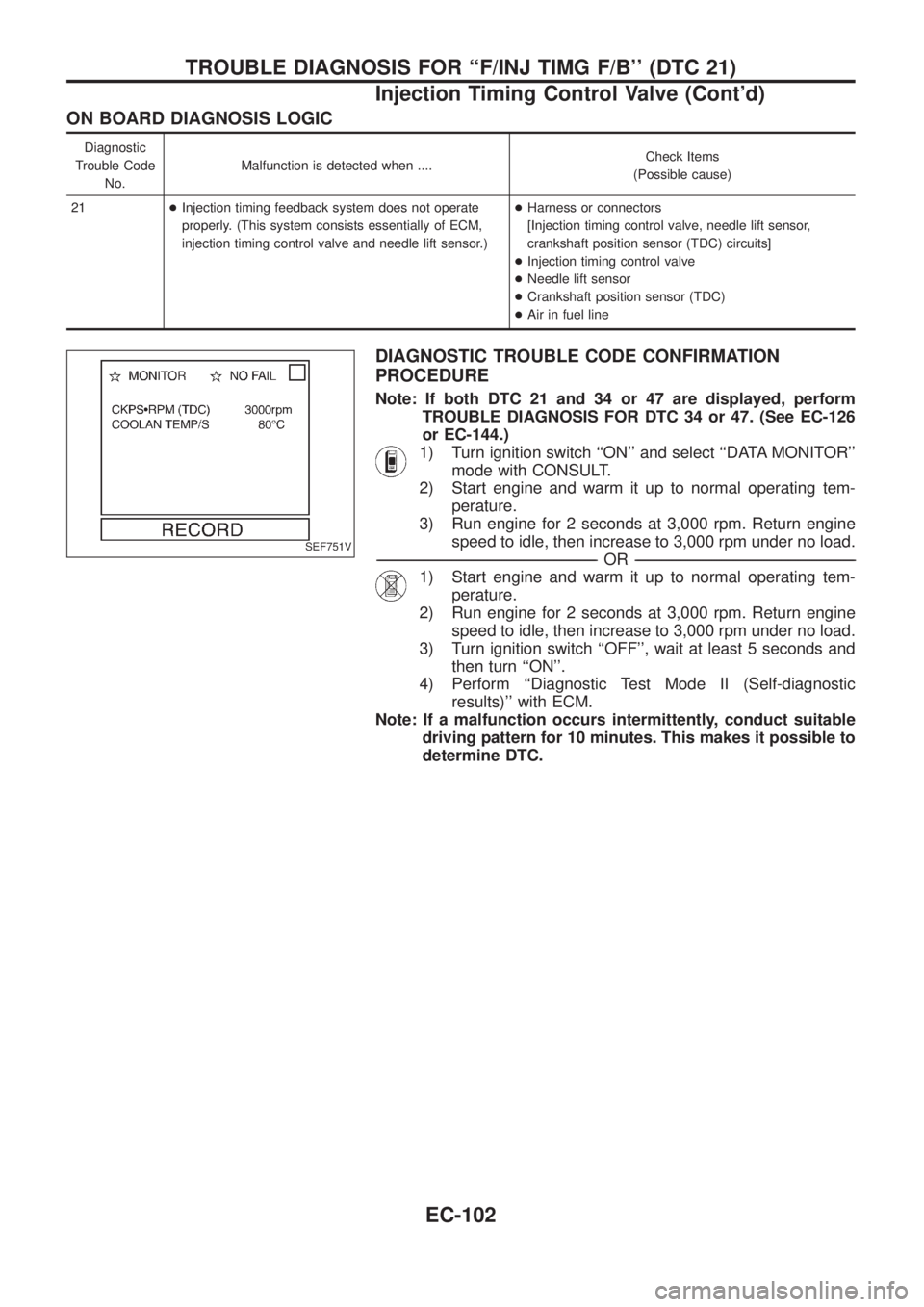
1) Turn ignition switch ``ON'' and select ``DATA MONITOR''
mode with CONSULT.
2) Start engine and warm it up to normal operating tem-
perature.
3) Run engine for 2 seconds at 3,000 rpm. Return engine
speed to idle, then increase to 3,000 rpm under no load.
-------------------------------------------------------------------------------------------------------------------------------------------------------------------------------------------------------------------------------------------------------OR-------------------------------------------------------------------------------------------------------------------------------------------------------------------------------------------------------------------------------------------------------
1) Start engine and warm it up to normal operating tem-
perature.
2) Run engine for 2 seconds at 3,000 rpm. Return engine
speed to idle, then increase to 3,000 rpm under no load.
3) Turn ignition switch ``OFF'', wait at least 5 seconds and
then turn ``ON''.
4) Perform ``Diagnostic Test Mode II (Self-diagnostic
results)'' with ECM.
Note: If a malfunction occurs intermittently, conduct suitable
driving pattern for 10 minutes. This makes it possible to
determine DTC.
SEF751V
TROUBLE DIAGNOSIS FOR ``F/INJ TIMG F/B'' (DTC 21)
Injection Timing Control Valve (Cont'd)
EC-102
Page 263 of 1226
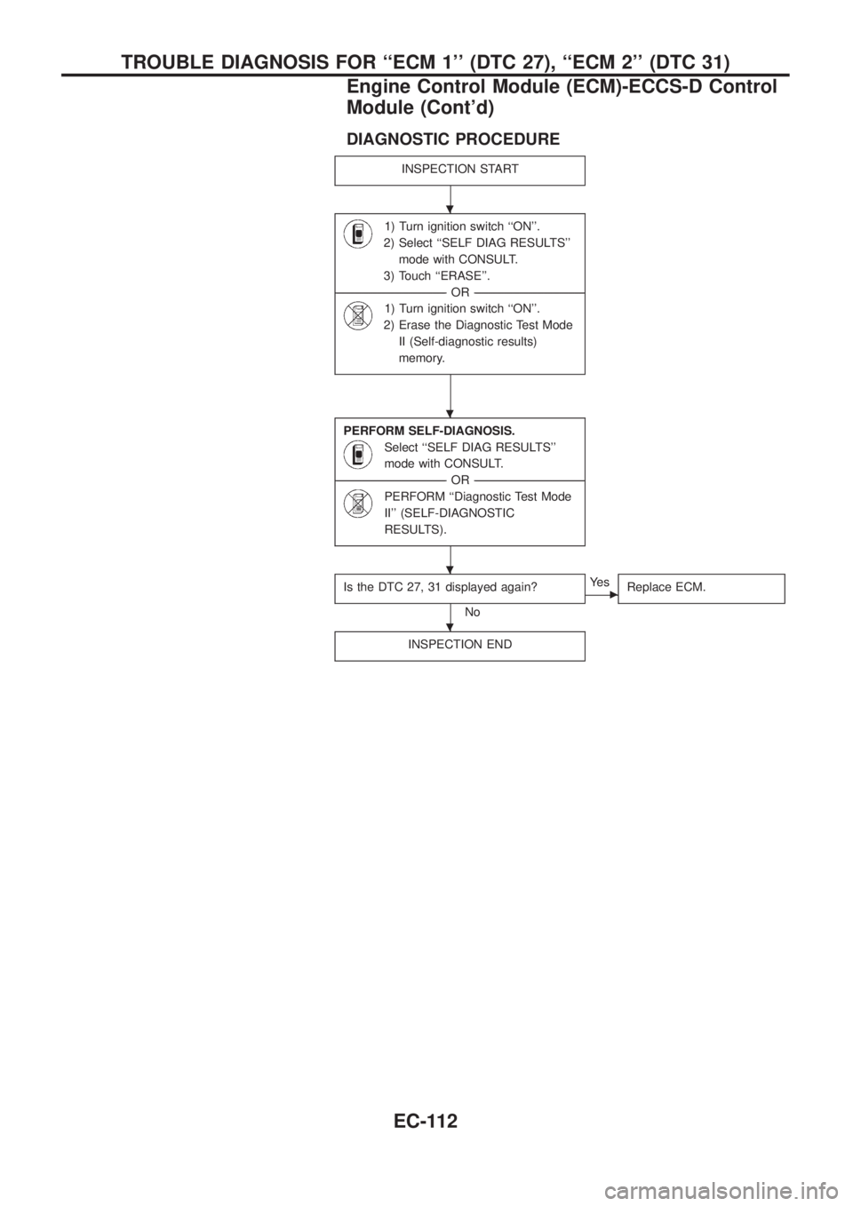
DIAGNOSTIC PROCEDURE
INSPECTION START
1) Turn ignition switch ``ON''.
2) Select ``SELF DIAG RESULTS''
mode with CONSULT.
3) Touch ``ERASE''.
--------------------------------------------------------------------------------------------------------------------------------------OR--------------------------------------------------------------------------------------------------------------------------------------
1) Turn ignition switch ``ON''.
2) Erase the Diagnostic Test Mode
II (Self-diagnostic results)
memory.
PERFORM SELF-DIAGNOSIS.
Select ``SELF DIAG RESULTS''
mode with CONSULT.
--------------------------------------------------------------------------------------------------------------------------------------OR--------------------------------------------------------------------------------------------------------------------------------------
PERFORM ``Diagnostic Test Mode
II'' (SELF-DIAGNOSTIC
RESULTS).
Is the DTC 27, 31 displayed again?
No
cYe s
Replace ECM.
INSPECTION END
.
.
.
.
TROUBLE DIAGNOSIS FOR ``ECM 1'' (DTC 27), ``ECM 2'' (DTC 31)
Engine Control Module (ECM)-ECCS-D Control
Module (Cont'd)
EC-112
Page 273 of 1226
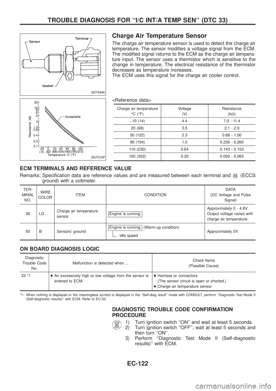
Charge Air Temperature Sensor
The charge air temperature sensor is used to detect the charge air
temperature. The sensor modi®es a voltage signal from the ECM.
The modi®ed signal returns to the ECM as the charge air tempera-
ture input. The sensor uses a thermistor which is sensitive to the
change in temperature. The electrical resistance of the thermistor
decreases as temperature increases.
The ECM uses this signal for the charge air cooler control.
Charge air temperatureÉC (ÉF) Voltage
(V) Resistance
(kW)
þ10 (14) 4.4 7.0 - 11.4 20 (68) 3.5 2.1 - 2.9
50 (122) 2.3 0.68 - 1.00
90 (194) 1.0 0.236 - 0.260
110 (230) 0.64 0.143 - 0.153
150 (302) 0.30 0.050 - 0.065
ECM TERMINALS AND REFERENCE VALUE
Remarks: Speci®cation data are reference values and are measured between each terminal andV43(ECCS
ground) with a voltmeter.
TER-
MINAL NO. WIRE
COLOR ITEM CONDITION DATA
(DC Voltage and Pulse Signal)
36 LG Charge air temperature
sensor Engine is running.
Approximatel
y 0 - 4.8V
Output voltage varies with
charge air temperature.
50 B Sensors' ground Engine is running.
(Warm-up condition)
Idle speed Approximately 0V
ON BOARD DIAGNOSIS LOGIC
Diagnostic
Trouble Code No. Malfunction is detected when ...
Check Items
(Possible Cause)
33 *1 +An excessively high or low voltage from the sensor is
entered to ECM. +
Harness or connectors
(The sensor circuit is open or shorted.)
+ Charge air temperature sensor
*1: When nothing is displayed or the meaningless symbol is displayed in the ``Self-diag result'' mode with CONSULT, perform ``Diagnostic Test Mode II
(Self-diagnostic results)'' with ECM. Refer to EC-32.
DIAGNOSTIC TROUBLE CODE CONFIRMATION
PROCEDURE
1) Turn ignition switch ``ON'' and wait at least 5 seconds.
2) Turn ignition switch ``OFF'', wait at least 5 seconds and then turn ``ON''.
3) Perform ``Diagnostic Test Mode II (Self-diagnostic results)'' with ECM.
SEF594K
SEF012P
TROUBLE DIAGNOSIS FOR ``I/C INT/A TEMP SEN'' (DTC 33)
EC-122
Page 300 of 1226
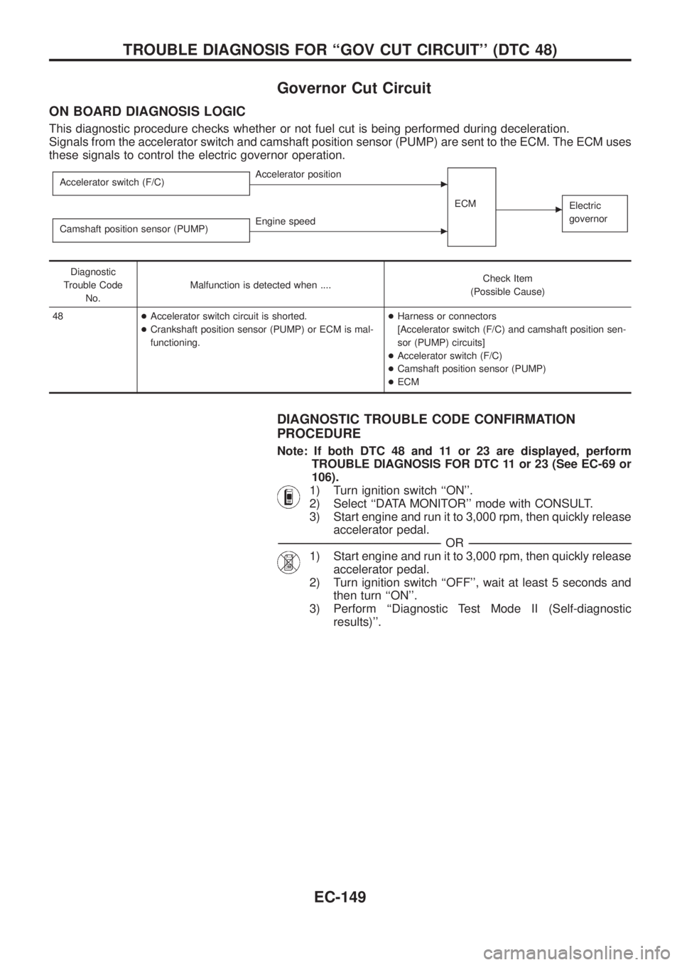
Governor Cut Circuit
ON BOARD DIAGNOSIS LOGIC
This diagnostic procedure checks whether or not fuel cut is being performed during deceleration.
Signals from the accelerator switch and camshaft position sensor (PUMP) are sent to the ECM. The ECM uses
these signals to control the electric governor operation.
Accelerator switch (F/C)cAccelerator position
ECM
cElectric
governor
Camshaft position sensor (PUMP)cEngine speed
Diagnostic
Trouble Code
No.Malfunction is detected when ....Check Item
(Possible Cause)
48+Accelerator switch circuit is shorted.
+Crankshaft position sensor (PUMP) or ECM is mal-
functioning.+Harness or connectors
[Accelerator switch (F/C) and camshaft position sen-
sor (PUMP) circuits]
+Accelerator switch (F/C)
+Camshaft position sensor (PUMP)
+ECM
DIAGNOSTIC TROUBLE CODE CONFIRMATION
PROCEDURE
Note: If both DTC 48 and 11 or 23 are displayed, perform
TROUBLE DIAGNOSIS FOR DTC 11 or 23 (See EC-69 or
106).
1) Turn ignition switch ``ON''.
2) Select ``DATA MONITOR'' mode with CONSULT.
3) Start engine and run it to 3,000 rpm, then quickly release
accelerator pedal.
-------------------------------------------------------------------------------------------------------------------------------------------------------------------------------------------------------------------------------------------------------OR-------------------------------------------------------------------------------------------------------------------------------------------------------------------------------------------------------------------------------------------------------
1) Start engine and run it to 3,000 rpm, then quickly release
accelerator pedal.
2) Turn ignition switch ``OFF'', wait at least 5 seconds and
then turn ``ON''.
3) Perform ``Diagnostic Test Mode II (Self-diagnostic
results)''.
TROUBLE DIAGNOSIS FOR ``GOV CUT CIRCUIT'' (DTC 48)
EC-149
Page 301 of 1226
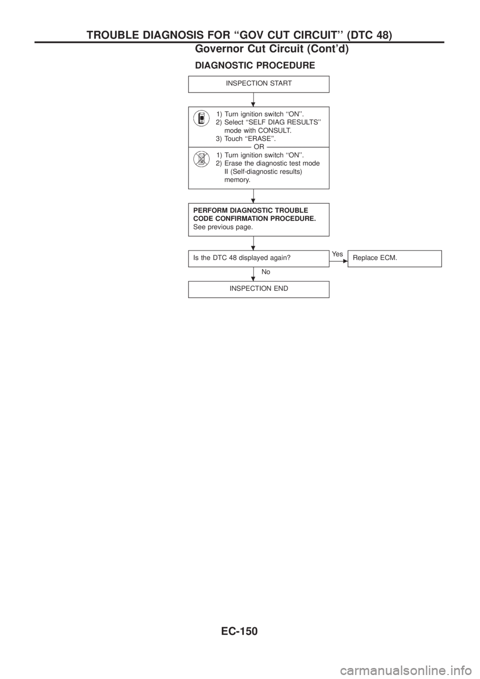
DIAGNOSTIC PROCEDURE
INSPECTION START
1) Turn ignition switch ``ON''.
2) Select ``SELF DIAG RESULTS''
mode with CONSULT.
3) Touch ``ERASE''.
--------------------------------------------------------------------------------------------------------------------------------------OR--------------------------------------------------------------------------------------------------------------------------------------
1) Turn ignition switch ``ON''.
2) Erase the diagnostic test mode
II (Self-diagnostic results)
memory.
PERFORM DIAGNOSTIC TROUBLE
CODE CONFIRMATION PROCEDURE.
See previous page.
Is the DTC 48 displayed again?
No
cYe s
Replace ECM.
INSPECTION END
.
.
.
.
TROUBLE DIAGNOSIS FOR ``GOV CUT CIRCUIT'' (DTC 48)
Governor Cut Circuit (Cont'd)
EC-150