2006 MITSUBISHI LANCER check engine
[x] Cancel search: check enginePage 68 of 800

CHARGING SYSTEM
ENGINE ELECTRICAL16-6
9. Check that the reading on the voltmeter is equal
to the battery voltage.
NOTE: If the voltage is 0 V, the cause is probably
an open circuit in the wire or fusible link between
the alternator "B" terminal and the battery (+) ter
-
minal.
10.Turn the light switch on to turn on headlamps and
then start the engine.
11.Immediately after setting the headlamps to high
beam and turning the heater blower switch to the
high revolution position, increase the engine
speed to 2,500 r/min and read the maximum
current output value displayed on the ammeter.
Limit: 70 % of normal current output
NOTE: .
•For the nominal current output, refer to the
Alternator Specifications.
•Because the current from the battery will soon
drop after the engine is started, the above step
should be carried out as quickly as possible in
order to obtain the maximum current output
value.
•The current output value will depend on the
electrical load and the temperature of the
alternator body.
•If the electrical load is small while testing, the
specified level of current may not be output
even though the alternator is normal. In such
cases, increase the electrical load by leaving
the headlamps turned on for some time to dis
-
charge the battery or by using the lighting sys-
tem in another vehicle, and then test again.
•The specified level of current also may not be
output if the temperature of the alternator body
or the ambient temperature is too high. In such
cases, cool the alternator and then test again.
12.The reading on the ammeter should be above the
limit value. If the reading is below the limit value
and the alternator output wire is normal, remove
the alternator from the engine and check the
alternator.
13.Run the engine at idle after the test.
14.Turn the ignition switch to the "LOCK" (OFF)
position.
15.Remove the tachometer or the M.U.T.-II/III.
16.Disconnect the negative battery cable.
17.Disconnect the ammeter and voltmeter.
18.Connect the negative battery cable.
Page 69 of 800

Page 71 of 800

CHARGING SYSTEM
ENGINE ELECTRICAL16-9
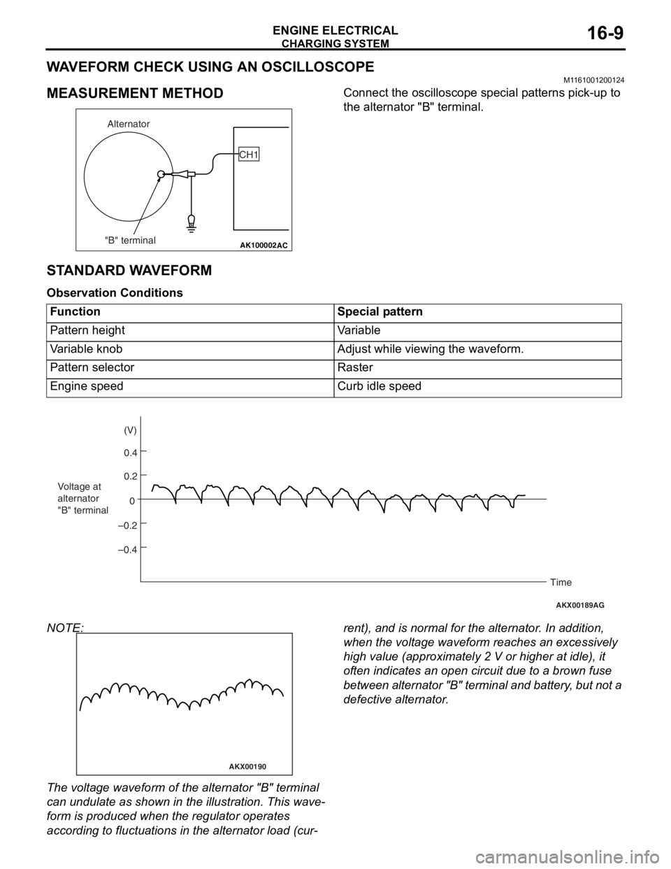
WAVEFORM CHECK USING AN OSCILLOSCOPE
M1161001200124
MEASUREMENT METHOD
AK100002
Alternator
"B" terminal CH1
AC
Co
nnect the oscillo scope specia l p a tt erns p i ck-up to
the alternato
r "B" terminal.
STANDARD W A VEFORM
Observ ation Conditi ons
FunctionSpecial pattern
Pattern heightVariable
Variable knobAdjust while viewing the waveform.
Pattern selectorRaster
Engine speedCurb idle speed
AKX00189
0.4 (V)
0.2
0
–0.2
–0.4
Voltage at
alternator
"B" terminal
Time
AG
NOTE:
AKX00190
The volt age waveform of th e alte rnator "B" t e rminal
can u
ndulate as sho w n in th e illustratio n . This wave
-
form is produce d when t he regu lator operate s
accordin
g to fluctu ation s in the alterna t or loa d (cu r
-
rent), and is normal fo r the alterna t or . In ad dition,
wh
en the volt ag e wavef o rm re ache s an excessively
high
value (app roximate ly 2 V or higher at idle ), it
of
ten indicates an o pen circuit du e to a brown fuse
be
twe e n a l te rn at or "B " t e r m in al an d ba tt er y , b u t n o t a
defective alte
rnator .
Page 72 of 800

CHARGING SYSTEM
ENGINE ELECTRICAL16-10
EXAMPLE OF ABNORMAL WAVEFORMS
NOTE: .
1. The size of the waveform patterns differs largely, depending on the adjustment of the variable knob on the
oscilloscope.
2. Identification of abnormal waveforms is easier when th ere is a large output current (regulator is not oper-
ating). (Waveforms can be observed when the headlamps are illuminated.)
3. Check the conditions of the charging warning lamp (illuminated/not illum inated). Also, check the charging
system totally.
Abnormal waveformProblem cause
Example 1
AKX00191
Open diod e
Exampl e 2
AKX00192
Shor t in diode
Page 79 of 800

CHARGING SYSTEM
ENGINE ELECTRICAL16-17
>>B<< ROTOR INSTALLATION
AK202779
Wire
AB
Remove the br ush holding wire af ter the rotor ha s
been inst
alled.
INSPECTION
M1161 0017 0015 2
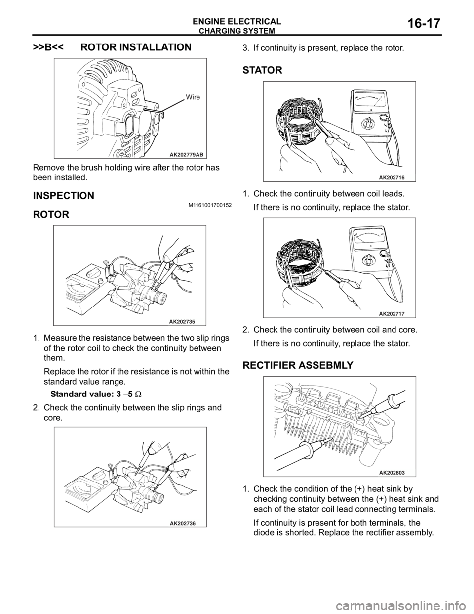
ROTO R
AK202735
1. Measure th e resist a n ce b e tween the two slip rings
of the rot o r coil to check t he co ntinu i ty between
th em.
Repla c e th e r o to r if th e resist ance is no t within the
st
a ndard valu e range .
St andard va lue: 3 − 5 Ω
2.Check t he co ntinu i ty between the slip rings and
core.
AK202736
3. If cont inuity is pre s ent, repla c e th e rotor .
STA T OR
AK202716
1.Check t he co ntinu i ty between coil le ads.
If there is no con t inuity , replace the st a t or .
AK202717
2.Check t he co ntinu i ty between coil and core .
If there is no con t inuity , replace the st a t or .
RECTIFIER ASSEBMLY
AK202803
1.Check t he co ndition o f the (+) h eat sink by
checkin g contin uity be twe en t he (+) heat sink and
e a ch o f the st a t or coil lead conn ecting termina l s.
If cont inuity is pre s ent for both terminals, the
d
i ode is shorte d. Repla c e th e rectifie r assembly .
Page 80 of 800

AK202802
CHARGING SYSTEM
ENGINE ELECTRICAL16-18
2.Check t he co ndition of the (−) heat sink by
checkin
g
con
t
inuity b
e
tween th e (
−) he at sink and
ea
ch o
f
the st
a
t
or co
il lead conne
cting termina l s.
If con t inu i ty is p r ese n t in bot h d i re ctio ns, the dio de
is shorted.
Re place the rectifier assembly .
AK202804
3.Check t he co ndition of the diode t r io by testing
continuity of ea ch o f the th ree diodes using a
circuit tester con necte d to both sides of the dio de.
Co nnect in a p o la rity a nd then reverse the polarity
fo r each test.
If continuity exist s or no cont inuity exist s for bo th
po
larities, the d i ode is d e fective . Repla c e th e
rectifier assembly if a
n y o f the d i odes is defe c tive.
BRUSH
AK202808
Protrusion
length
AB
1.Measure the lengt h of the prot rusion o f the bru s h.
Replace the b r ush if the protrusion lengt h is
shorter than th e limit .
Limit: 2 mm mini mum
2.Unsolde r the lead o f the br ush. The bru s h will
come out, b e coming ready for removal.
AK202834
Solder
AB
3.I n st all a ne w b r ush b y pu sh in g it int o the h o lde r a s
shown in the d r awing a nd soldering th e lea d .
Page 85 of 800

STARTING SYSTEM
ENGINE ELECTRICAL16-23
STARTER MOTOR ASSEMBLY INSPECTION
M1162001100205
PINION GAP ADJUSTMENT
AK300648AB
<4G1>
Switch
S M
Wire Battery
Starter
motor
B
AKX01238
<4G6>
B
M S
battery Switch
Starter
motorWire
AG
1.
Disco nnect the field coil wire f r om th e M-te rmin al
of the magnet ic switch.
2.Conn ect a 12-volt b a ttery between the S-termina l
an d M-t e rminal.
CAUTION
This test must be performed quickly (in less than
10 seconds) to prevent the coil from burning.
3. Set the switch to "ON", and the pinion will move out.
AKX00198
Stopper
Pinion gap
Pinion
AC
4. Check the pinion-to-stopper clearance (pinion
gap) with a feeler gauge.
Standard value: 0.5 − 2.0 mm
AKX00199
5. If the pinion gap is out of specification, adjust by adding or removing gasket(s) between the
magnetic switch and front bracket.
MAGNETIC SWITCH PULL-IN TEST
AK300649AB
<4G1>
SM
Wire Battery
Starter
motor
B
AKX01242
<4G6>
SB
M
Battery
Starter
motorWire
AF
1. Disconnect the field coil wire from the M-terminal
of the magnetic switch.
CAUTION
This test must be performed quickly (in less than
10 seconds) to prevent the coil from burning.
2. Connect a 12-volt battery between the S-terminal and M-terminal.
3. If the pinion moves out, the pull-in coil is good. If it doesn't, replace the magnetic switch.
Page 90 of 800

AK202711
SegmentUndercut
Mica
AB
ST ARTING SYS TEM
ENGINE ELECTRICAL16-28
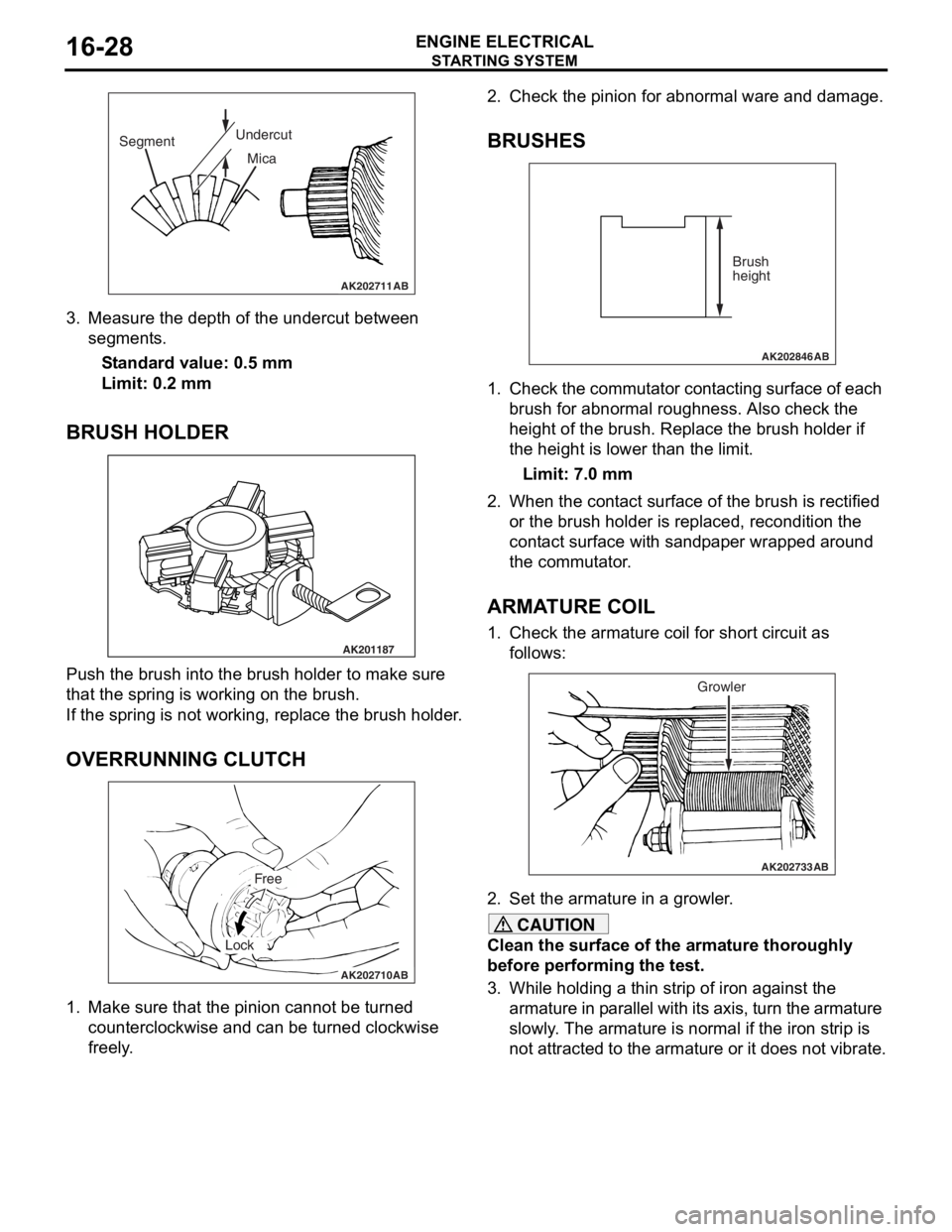
3.Measure the depth of the undercut be twe en
segment s.
St andard va lue: 0.5 mm
Limit: 0.2 mm
BRUSH HOLDER
AK201187
Push th e brush in to the b r ush hold e r to make sure
that the
spring is working o n the b r ush.
If the spring is not working, repla c e th e brush holder .
OVERRUNNING CLUTCH
AK202710
Free
Lock
AB
1.Make sure that th e pin i on canno t be tu rned
counte r clo ckwise a nd ca n be tu rned clockwise
fre e ly .
2.Check t he pinion for abn ormal ware an d damage.
BRUSHES
AK202846
Brush
height
AB
1.Che ck the commut ator con t a c tin g surface of each
b r ush f o r abno rmal rough ness. Also ch eck the
h e ight of the brush . Replace th e brush holder if
th e height is lo we r than t he limit.
Limit: 7.0 mm
2.Wh en the con t act su rface of the brush is rectified
o r the bru s h h o lder is re placed, re cond itio n the
cont act surfa c e wit h san d p a p e r wrapped around
th e co mmu t a t o r .
ARMATURE COIL
1.Check t he armature coil for short circuit a s
fo llows:
AK202733
Growler
AB
2.Set the armature in a growler .
CAUTION
Clean the surface of the armature thoroughly
before performing the test.
3. While holding a thin strip of iron against the
armature in parallel with it s axis, turn the armature
slowly. The armature is normal if the iron strip is
not attracted to the armature or it does not vibrate.