2006 MITSUBISHI LANCER check engine
[x] Cancel search: check enginePage 91 of 800

AK202734
STARTING SYSTEM
ENGINE ELECTRICAL16-29
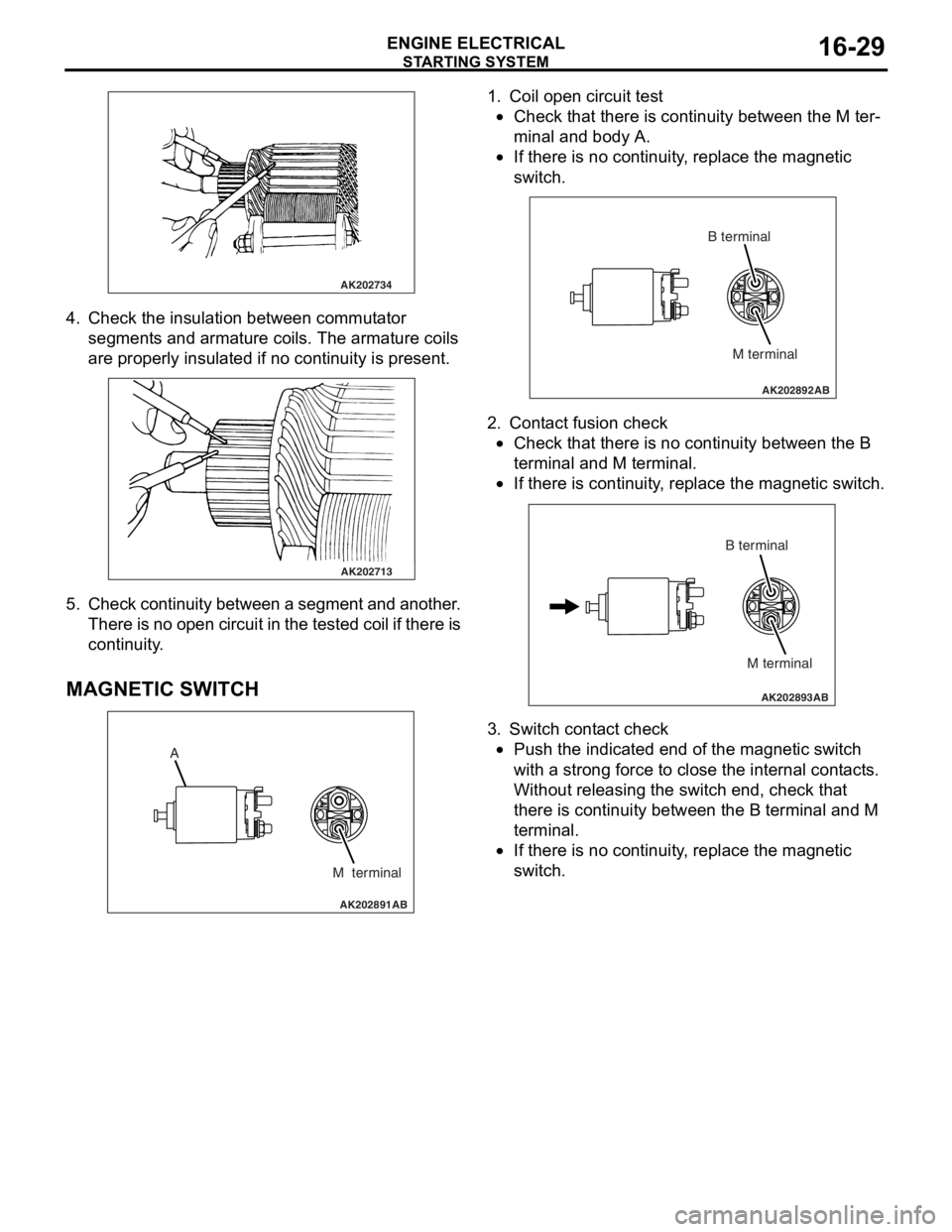
4. Check t he in sulation between commut ator
segment s an d arma ture coils. Th e armature coils
are prope rly insu lated if no con t inuity is pre s ent .
AK202713
5. Check continuit y bet ween a segment and another .
Th ere is n o ope n circui t in th e t e s t e d c o il if t h e r e is
continuity .
MA GNETIC SW ITCH
AK202891
A
M terminal
AB
1.Coil ope n circuit test
•Check that there is continuity be twe en the M te r-
minal and body A.
•
AK202892
M terminal
B terminal
AB
If th
ere is no continuit y , replace t he ma gnetic
sw
itc h .
2.Cont act fusion check
•Check that there is no co ntinu i ty between the B
termina
l and M te rmin al.
•
AK202893
M terminal
B terminal
AB
If th
ere is co ntinu i ty , re place the magn etic switch.
3.Switch cont act check
•Push the indicated end o f the magne tic switch
with
a stro ng force to close th e inte rnal cont act s .
Without re
leasing the switch end, check tha t
the
r e is con t inuity b e tween th e B terminal and M
termina
l .
•If there is no continuit y , replace t he ma gnetic
sw
itc h .
Page 94 of 800

IGNITION SYSTEM
ENGINE ELECTRICAL16-32
ON-VEHICLE SERVICE
IGNITION COIL (WITH BUILT-IN POWER
TRANSISTOR) CHECK
M1163001200324
Check by the following procedure, and replace if
there is a malfunction.
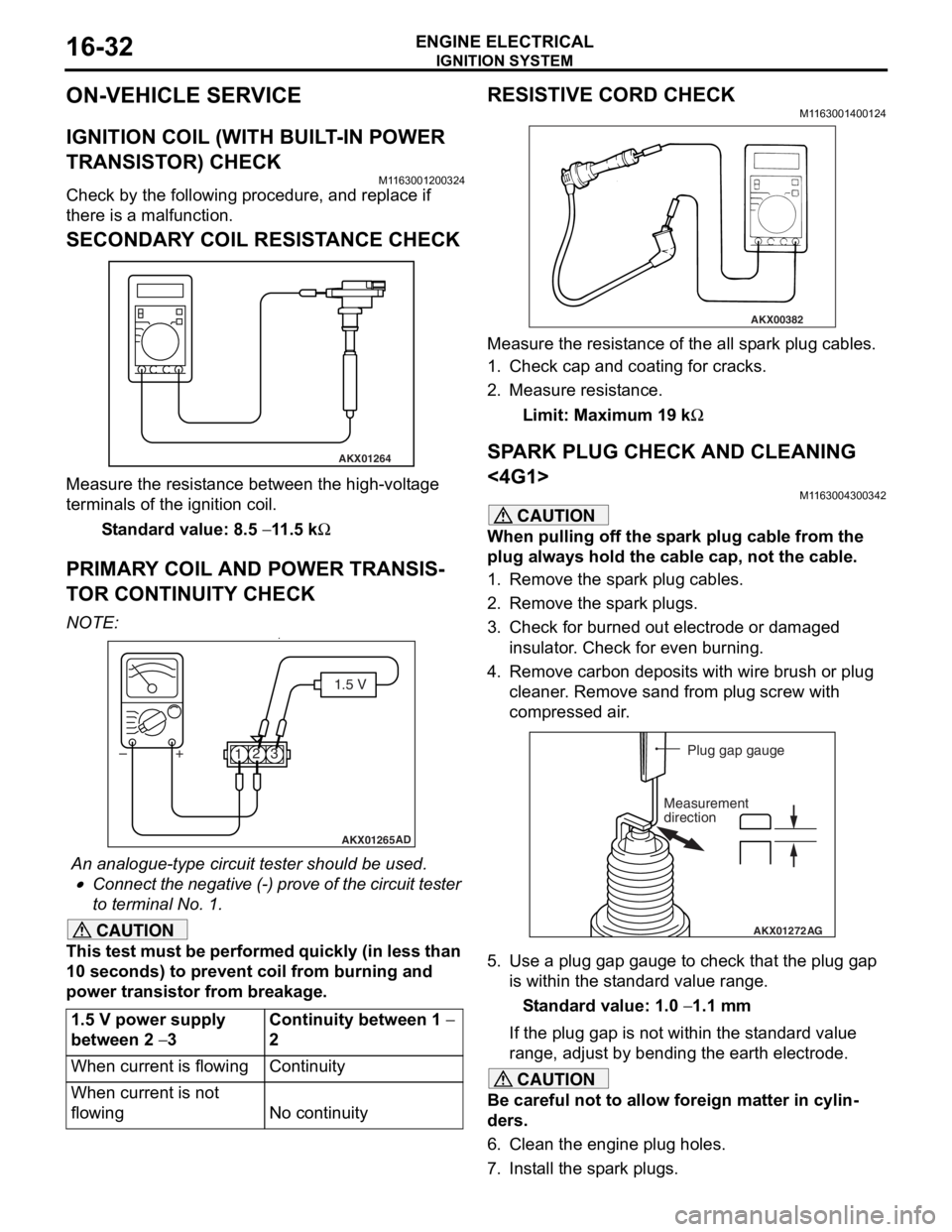
SECONDARY COIL RESISTANCE CHECK
AKX01264
Measure the resist ance bet we en the high- volt ag e
terminals of th
e ign i tio n coil.
St andard va lue: 8.5 − 11 .5 kΩ
PRIM AR Y COIL AND POWER TRANSIS-
TO R CONTINUITY CHECK
NO TE: .•
AKX01265 AD
1.5 V
1 23
+
–
An analogue-t y pe circuit t e ster shou ld be use d .
•Connect the n egative (-) pro v e of the circuit t e ster
to t
e rminal No. 1.
CAUTION
This test must be performed quickly (in less than
10 seconds) to prevent coil from burning and
power transistor from breakage.
1.5 V power supply
between 2
− 3
Continuity between 1 −
2
When current is flowingContinuity
When current is not
flowing
No continuity
RESISTIVE CORD CHECK
M1163001400124
AKX00382
Measure the resistance of the all spark plug cables.
1. Check cap and coating for cracks.
2. Measure resistance.
Limit: Maximum 19 kΩ
SPARK PLUG CHECK AND CLEANING
<4G1>
M1163004300342
CAUTION
When pulling off the spark plug cable from the
plug always hold the cable cap, not the cable.
1. Remove the spark plug cables.
2. Remove the spark plugs.
3. Check for burned out electrode or damaged insulator. Check for even burning.
4. Remove carbon deposits with wire brush or plug cleaner. Remove sand from plug screw with
compressed air.
AKX01272 AG
Plug gap gauge
Measurement
direction
5. Use a plug gap gauge to check that the plug gap is within the standard value range.
Standard value: 1.0 − 1.1 mm
If the plug gap is not within the standard value
range, adjust by bending the earth electrode.
CAUTION
Be careful not to allow foreign matter in cylin-
ders.
6. Clean the engine plug holes.
7. Install the spark plugs.
Page 95 of 800

IGNITION SYSTEM
ENGINE ELECTRICAL16-33
SPARK PLUG CHECK AND CLEANING
<4G6>
M1163004300353
CAUTION
When pulling off the spark plug cable from the
plug always hold the cable cap, not the cable.
1. Remove the spark plug cables.
2. Remove the spark plugs.
CAUTION
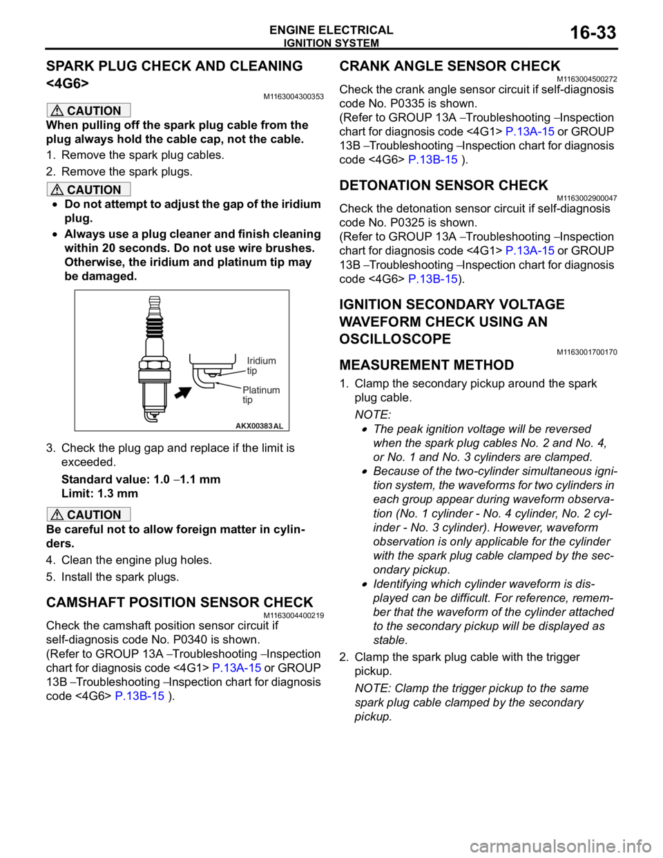
•Do not attempt to adjust the gap of the iridium
plug.
•
AKX00383 AL
Platinum
tipIridium
tip
Always use a plug cleaner and finish cleaning
within 20 seconds. Do not use wire brushes.
Otherwise, the iridium and platinum tip may
be damaged.
3. Check the plug gap and re
place if the limit is
exceeded.
Standard value: 1.0 − 1.1 mm
Limit: 1.3 mm
CAUTION
Be careful not to allow foreign matter in cylin-
ders.
4. Clean the engine plug holes.
5. Install the spark plugs.
CAMSHAFT POSITION SENSOR CHECK
M1163004400219
Check the camshaft position sensor circuit if
self-diagnosis code No. P0340 is shown.
(Refer to GROUP 13A − Troubleshooting − Inspection
chart for diagnosis code <4G1>
P.13A-15 or GROUP
13B − Troubleshooting − Inspection chart for diagnosis
code <4G6>
P.13B-15 ).
CRANK ANGLE SENSOR CHECK
M1163004500272
Check the crank angle sensor circuit if self-diagnosis
code No. P0335 is shown.
(Refer to GROUP 13A − Troubleshooting − Inspection
chart for diagnosis code <4G1>
P.13A-15 or GROUP
13B − Troubleshooting − Inspection chart for diagnosis
code <4G6>
P.13B-15 ).
DETONATION SENSOR CHECKM1163002900047
Check the detonation sensor circuit if self-diagnosis
code No. P0325 is shown.
(Refer to GROUP 13A − Troubleshooting − Inspection
chart for diagnosis code <4G1>
P.13A-15 or GROUP
13B − Troubleshooting − Inspection chart for diagnosis
code <4G6>
P.13B-15).
IGNITION SECONDARY VOLTAGE
WAVEFORM CHECK USING AN
OSCILLOSCOPE
M1163001700170
MEASUREMENT METHOD
1. Clamp the secondary pickup around the spark
plug cable.
NOTE: .
•The peak ignition voltage will be reversed
when the spark plug cables No. 2 and No. 4,
or No. 1 and No. 3 cylinders are clamped.
•Because of the two-cylinder simultaneous igni-
tion system, the waveforms for two cylinders in
each group appear during waveform observa
-
tion (No. 1 cylinder - No. 4 cylinder, No. 2 cyl-
inder - No. 3 cylinder). However, waveform
observation is only applicable for the cylinder
with the spark plug cable clamped by the sec
-
ondary pickup.
•Identifying which cylinder waveform is dis-
played can be difficult. For reference, remem-
ber that the waveform of the cylinder attached
to the secondary pickup will be displayed as
stable.
2. Clamp the spark plug cable with the trigger pickup.
NOTE: Clamp the trigger pickup to the same
spark plug cable clamped by the secondary
pickup.
Page 99 of 800

IGNITION SYSTEM
ENGINE ELECTRICAL16-37
IGNITION COIL RELAY CHECK
M1163006500018
AC301727
2 1
3
4
AC304311AB
Battery
Ignition coil relay
Battery
voltageTerminal No.to
be connected
to testerContinuity test
results
Not applied1 − 4Open circuit
Connect
terminal No.2
and battery (+)
terminal.
Connect
terminal No.3
and battery (
−)
terminal.
1 − 4Less than 2
ohms
Page 107 of 800

17-1
GROUP 17
ENGINE AND
EMISSION
CONTROL
CONTENTS
ENGINE CONTROL . . . . . . . . . .17-2
GENERAL INFORMATION . . . . . .17-2
SERVICE SPECIFICATIONS. . . . .17-2
ON-VEHICLE SERVICE. . . . . . . . .17-2
ACCEL CABLE CHECK AND
ADJUSTMENT . . . . . . . . . . . . . . . . . . . . 17-2
ACCELERATOR CABLE AND
PEDAL . . . . . . . . . . . . . . . . . . . . . .17-3
REMOVAL AND INSTALLATION . . . . . 17-3
EMISSION CONTROL MPI . . . .17-4
GENERAL INFORMATION . . . . . .17-4
EMISSION CONTROL DEVICE
REFERENCE TABLE . . . . . . . . . .17-4
SERVICE SPECIFICATION(S) . . .17-5
VACUUM HOSE. . . . . . . . . . . . . . .17-5
VACUUM HOSE PIPING DIAGRAM . . . 17-5
VACUUM CIRCUIT DIAGRAM . . . . . . . 17-7
VACUUM HOSE CHECK. . . . . . . . . . . . 17-7
VACUUM HOSE INSTALLATION . . . . . 17-8
CRANKCASE EMISSION CONTROL
SYSTEM . . . . . . . . . . . . . . . . . . . . .17-8
GENERAL INFORMATION (CRANKCASE
EMISSION CONTROL SYSTEM) . . . . . 17-8
COMPONENT LOCATI ON (CRANKCASE
EMISSION CONTROL SYSTEM) . . . . . 17-9
POSITIVE CRANKCASE VENTILATION SYSTEM
CHECK . . . . . . . . . . . . . . . . . . . . . . . . . 17-9
POSITIVE CRANKCASE VENTILATION (PCV)
VALVE CHECK . . . . . . . . . . . . . . . . . . . 17-9
EVAPORATIVE EMISSION CONTROL
SYSTEM . . . . . . . . . . . . . . . . . . . . .17-9
GENERAL INFORMATION (EVAPORATIVE
EMISSION CONTROL SYSTEM) . . . . . 17-9
COMPONENT LOCATION (EVAPORATIVE
EMISSION CONTROL SYSTEM) . . . . . 17-10
PURGE CONTROL SYSTEM CHECK . . 17-10
PURGE PORT VACUUM CHECK . . . . . 17-11
PURGE CONTROL SOLENOID VALVE
CHECK . . . . . . . . . . . . . . . . . . . . . . . . . . 17-11
FUEL VAPOUR CANISTER REMOVAL
AND INSTALLATION . . . . . . . . . . . . . . . 17-12
EXHAUST GAS RECIRCULATION
(EGR) SYSTEM . . . . . . . . . . . . . . .17-12
GENERAL INFORMATION
(EGR SYSTEM) . . . . . . . . . . . . . . . . . . . 17-12
COMPONENT LOCATION
(EGR SYSTEM) . . . . . . . . . . . . . . . . . . . 17-14
EGR SYSTEM CHECK . . . . . . . . . . . . . 17-15
EGR VALVE CHECK . . . . . . . . . . . . . . . 17-15
EGR PORT VACUUM CHECK <4G1>. . 17-16
EGR PORT VACUUM CHECK <4G6>. . 17-16
EGR CONTROL SOLENOID VALVE
CHECK <4G1> . . . . . . . . . . . . . . . . . . . . 17-16
EGR CONTROL SOLENOID VALVE
CHECK <4G6> . . . . . . . . . . . . . . . . . . . . 17-17
EXHAUST GAS RECIRCULATION (EGR)
VALVE REMOVAL AND I
NSTALLATION . . . . . . . . . . . . . . . . . . . . 17-18
CATALYTIC CONVERTER . . . . . .17-19
REMOVAL AND INSTALLATION
<4G1, 4G6-M/T> . . . . . . . . . . . . . . . . . . 17-19
REMOVAL AND INSTALLATION
<4G6-A/T> . . . . . . . . . . . . . . . . . . . . . . . 17-19
Page 108 of 800

ENGINE CONTROL
ENGINE AND EMISSION CONTROL17-2
ENGINE CONTROL
GENERAL INFORMATIONM1171000100277
A cable-type accelerator mechanical sus-
pended-type pedal has been adopted.
SERVICE SPECIFICATIONS
M1171000300088
ItemStandard value
Accel cable play mm1.0 − 2.0
Engine idle speed r/min4G1750 ± 50
4G6750 ± 100
ON-VEHICLE SERVICE
ACCEL CABLE CHECK AND
ADJUSTMENT
M1171000900314
1. Turn A/C and lights OFF. Inspect and adjust at no load.
2. Warm engine until stabilized at idle.
3. Confirm idle speed is at standard value.
Standard value:
750 ± 50 r/min <4G1>
750 ± 100 r/min <4G6>
4. Stop engine. [ignition switch: LOCK (OFF)
position].
5. Confirm there are no sharp bends in the accelerator cable.
6. Check the inner cable for correct slack.
Standard value: 1.0 − 2.0 mm
7. If there is too much slack or no slack, adjust play by the following procedures.
AC207966
Adjusting bolts
Plate
Accel cable
AC
<4G1>
AC301055
Adjusting bolts
Plate
Accel cable
AC
<4G6>
(1) Loosen th e adjusting bo lt s to re lease the
cab l e.
(2) M o v e th e pla t e until the inne r cab l e play is a t
the st andard value, an d then tighte n the
adjusting bo lt s.
(3) A f t e r adju s ting, check that the thro ttle leve r is
touching the stoppe r .
Page 113 of 800

EMISSION CONTROL
ENGINE AND EMISSION CONTROL17-7
VACUUM CIRCUIT DIAGRAM
M1173007100263
AK300765
From
air
cleaner
To
combustion
chamber Throttle body
B
R
AB
Intake manifold
Y
G
G G R
L
Fuel
pressure
regulator
EGR
valve EGR
control
solenoid
valve
Purge
control
solenoid
valveCanister
Vacuum hose colour
B: Black
G: Green
R: Red
Y: Yellow
L: Blue
<4G1>
AK300766
From
air
cleaner
To
combustion
chamber Throttle body
B
B
AB
Intake manifold
Y
R
G W
L
Fuel
pressure
regulator
EGR
valveEGR
control
solenoid
valve
Purge
control
solenoid
valveCanister
Vacuum hose colour
B: Black
G: Green
R: Red
W: White
Y: Yellow
L: Blue
<4G6>
B
V ACUUM HOSE CHECK
M1 173 0073 0015 9
1.Using th e pip i ng d i agra m as a gu ide, check to be
sure th at the vacuum h o ses are correctly
connected.
2. Check t he co nnection cond itio n of th e vacuum
ho s e s, (re mo v e d, l o os e , et c . ) an d c h e c k t o b e
sure th at there are no bends or da mage .
Page 115 of 800

EMISSION CONTROL
ENGINE AND EMISSION CONTROL17-9
COMPONENT LOCATION (CRANKCASE
EMISSION CONTROL SYSTEM)
M1173007400208
AK300767
<4G1>
AB
PCV valve
AK204366
<4G6>
AC
PCV valve
POSITIVE CRANKCASE VENTILATION
SYSTEM CHECK
M11 7300 1 1 0017 9
1.Remove the ventilatio n hose from the PCV valve.
2.Remove the PCV valve from t he rocker cove r .
3.Reinst all the PCV valve at the ven t ila tion h o se.
4.S t art the engin e and run at idle .
AKX00336
PCV valve
AD
5.Pla c e a fing er at the open ing o f the PCV va lve
an d ch eck that vacu um o f the int a ke manifold is
fe lt.
NOTE: At this mo men t, the p l unge r in t he PCV
valve mo ves back an d forth.
6.If vacuum is not felt, clean t he PCV valve o r
re place it.
POSITIVE CRANKCASE VENTILA TION
(
P CV) V A L VE CHECK
M1173 0012 0018 7
AK100010
PCV valve
AC
1.In sert a thin rod in to the PCV valve from the side
shown in the illu strat i on (ro cke r cover in st allation
side) , and move the ro d back an d forth to ch eck
th at the plung er mo ves.
2.If the plunger does not move , there is a clo ggin g
in the PCV valve. In th is case, clean o r repla c e
th e PCV valve.
EVAPORA T IVE EMISSION CONTROL
SYSTEM
GENERAL INFORMA T ION (EV A PORA TIVE
EMISSION CONTROL SYSTEM)
M1173 0051 0040 5
The evaporat ive emission contro l syste m pre v ent s
f
uel vapours generat ed in t he fuel t ank from escaping
into t
he atmosp here.
Fuel vapours fro m the fuel t a n k flow throug h the f uel
t
a n k pre ssu re co ntrol valve an d vap our pipe/ho se to
be st
ored te mpora r ily in t he ca nister .
When dr iving the veh i cle, fue l va pours stor ed in the
canister
flow thro ugh th e purge solenoid and purge
port an
d go into the int a ke ma nifold to b e sen t to th e
combust
i on chamber .
When the eng ine co ola n t te mp eratu r e is low o r when
the int
a ke air q uantity is small (wh en the engine is at
idle
, for example), t he eng ine contro l unit turns the
purge sole
noid of f to shu t of f the fue l va pour flow to
the in
t a ke manif o ld.
This does not on ly insure the driveability when t he
engin
e is cold or runn ing und er low load b u t also st a
-
bilize the emissio n level.