Page 353 of 364

CVT
CONTINUOUSLY VARIABLE TRANSMISSION (CVT)23-5
ATF WARMER (ATF COOLER)
M2230000600082
AC403052AC
AT F
Engine coolant
Sectional view
ATF Warmer
(ATF Cooler)
Thermo valve
AC403006
CVT CVT CVT
Thermostat
Thermo
valve
ATF warmer (ATF cooler)ATF warmer (ATF cooler)
: Engine coolant
: AT F
85˚C or more>
Engine coolant flows through
all the sections.
75 - 85˚C>
Engine coolant flows through
the heater and the ATF warmer.
75˚C or less>
Engine coolant flows through
the heater only.
AC
: Valve open
: Valve closed
Thermostat
Thermo
valve
ATF warmer (ATF cooler)Thermo
valve
Thermostat
Radiator
Engine Heater
Radiator Engine Heater
Radiator
Engine Heater
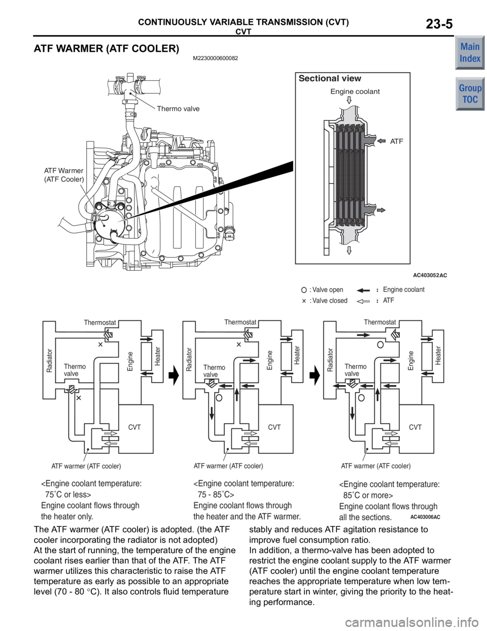
The A TF warme r (A TF cooler) is adop ted. (th e A TF
cooler in
corpo r ating the rad i ator is n o t ado pted)
At the st art of runn ing, th e tempe r ature of th e engine
coolant rises earlier tha
n that of the A T F . The A TF
war
m er ut ilizes this ch aract e ristic to raise the A TF
tempe
r ature a s ea rly a s po ssible to an a ppropriate
leve
l (70 - 80
°C). It also contro ls fluid temperature st ably and reduces A TF agit a tion resist ance to
imp r ove f uel consump t ion ra tio.
In addition
, a the r mo-valve has bee n adop ted to
restrict the eng
ine coolan t supply to the A TF warmer
(A
TF coole r) until the engine co olan t temperature
reach
e s th e appro p riat e temperature when low tem
-
perature st art in winter , giving the priority to th e heat-
ing pe rformance .
Page 357 of 364
TRANSMISSION CONTROL
CONTINUOUSLY VARIABLE TRANSMISSION (CVT)23-9
When the ignition key is in the LOCK (OFF) position or pulled out (With the selector
lever in the P position)
AC206911 AB
Slider
Ignition key �
LOCK (OFF) position
Projection of rotor
Key interlock cable
Lock cam
Rod
Lever
Engine starting
switch assembly
In the e
ngin e st arting switch a s sembly , the slider is
engage
d with t he groo ve o f the key interlock cab l e,
and the
slider is locked by the p r ojection of the rotor
so th
at the key interlock ca ble a s well as the lever ,
rod, and
lock cam d oes not move.As a result of this, an y att e mpt to sh if t the sele ctor
lever is prevented.
The pu shbu tton on the selector
lever can
not be pressed b e cau s e th e lock cam does
not rot
a te, then t he se lector le ver cannot be shif ted
from t
he P position to a nother position .
Page 358 of 364

TRANSMISSION CONTROL
CONTINUOUSLY VARIABLE TRANSMISSION (CVT)23-10
When the ignition key is in other than the LOCK (OFF) posi tion (With the selector
lever in the P position)
AC206912 AB
A
Slider
Ignition key
ACC to START
position
Projection of rotor
Key interlock cable
Lock cam
Rod
Lever
Engine starting
switch assembly
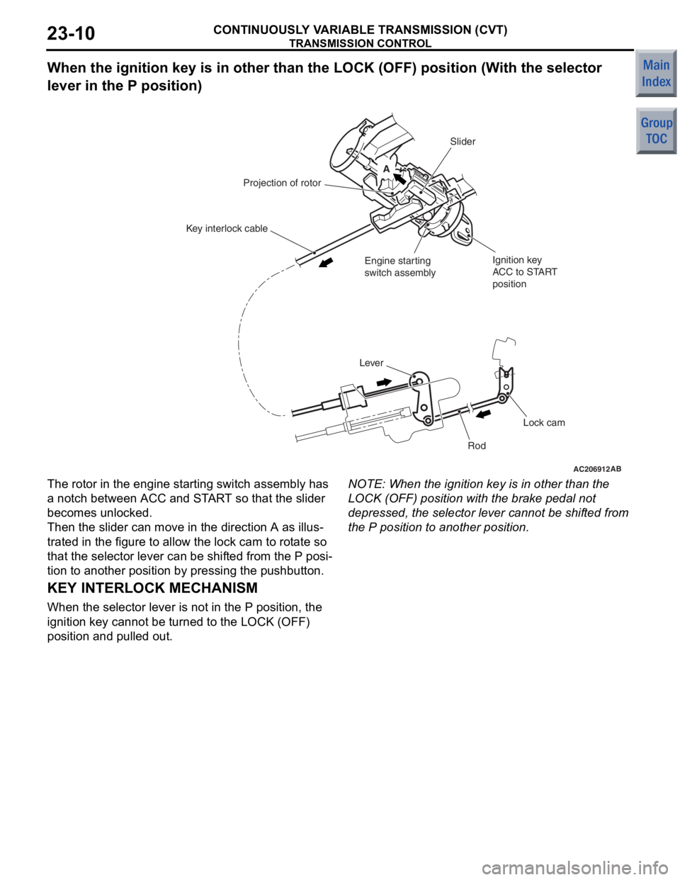
The roto
r in th e engine st a r ting switch assembly has
a notch betwee
n ACC a nd ST AR T so that th e slider
beco
m es unlo c ked.
Then the slider can move in t he direction A as illus-
trated in the figure to allow the lock cam to rot a te so
that the se
lector lever can be shif ted fro m the P posi
-
tion to anoth e r position by pressin g the p u shb u tton.
NOTE: Whe n the ignition key is in oth e r than the
LOCK (OFF) position with the bra k e pe dal n o t
depressed , the sele ctor leve r cann ot be shif ted fro m
the P position to anothe r positio n.
KEY INTERLOCK MECHANISM
When the se lect or lever is not in th e P positio n, the
ignition
key cann ot be turned to the L O CK (OF F )
position
and pu lle d out.
Page 359 of 364
TRANSMISSION CONTROL
CONTINUOUSLY VARIABLE TRANSMISSION (CVT)23-11
When pulling out the key with the selector lever in other than the P position
AC206912AC
B
A
A
Slider
Ignition key
ACC to START
position
Projection of rotor
Key interlock cable
Lock cam
Rod
Lever
Engine starting
switch assembly
The lo
ck cam is kep t in a rot a ted condition, and th e
key inte
rlock ca ble is kept p u lle d in direction A as
illustra
t ed in the figure. I n this st ate , the slider in the
e
ngine st a r ting swit ch asse mbly is moved and lo cked
in direction B as illustrated in the
figu re.As a result of th is, a n y at te mpt to t u rn th e ign i t i o n k e y
to the L
O CK (OFF) position is prevented beca u se
the slide
r prevent s the rotor fro m rot a ting, an d the
ignition key can only turn up to the
ACC position a nd
cann
ot be p u lle d out.
Page 360 of 364
TRANSMISSION CONTROL
CONTINUOUSLY VARIABLE TRANSMISSION (CVT)23-12
When pulling out the key with the selector lever in the P position
AC206911AC
A
A
Slider
Ignition key
ACC to START
position
Projection of rotor
Key interlock cable
Lock cam
Rod
Lever
Engine starting
switch assembly
Detent pin
When re leasing the push button on t he selector leve r
with the se
lector lever in the P position , the lock ca m
is ro
t a t ed by the d e tent p i n. Th en the key inte rlock
cable
is moved by the lo ck cam in dire ction A as illus
-
trated in the figure .
As a result of this, th e slider in the engine st arting
switch assembly is unlocked. The rotor can then turn,
and the
ign i tion key ca n be p u lle d out b y turn ing it to
the LOCK (OFF)
position .
Page 361 of 364
GROUP 17
ENGINE AND EMISSION
CONTROL
CONTENTS
ENGINE CONTROL . . . . . . . . . . . . . .17-2
ACCELERATOR SYSTEM . . . . . . . . . . . . . 17-2
EMISSION CONTROL . . . . . . . . . . . .17-3
GENERAL INFORMATION <4A9> . . . . . . . 17-3
GENERAL INFORMATION <4G1> . . . . . . . 17-4
Page 362 of 364
ENGINE CONTROL
ENGINE AND EMISSION CONTROL17-2
ENGINE CONTROL
ACCELERATOR SYSTEMM2170003000310
For the accelerator system, an electronic throttle
valve control system has been adopted, eliminating
of an accelerator cable. This system detects the
amount of the accelerator pedal movement by using
a accelerator pedal-position sensor in the accelerator
pedal assembly for electronic control of the throttle
valve angle.
CONSTRUCTION DIAGRAM
AC206106
Accelerator pedal assembly
(Built-in accelerator pedal
position sensor)
Accelerator pedal
arm stopper
AD
Page 363 of 364

EMISSION CONTROL
ENGINE AND EMISSION CONTROL17-3
EMISSION CONTROL
GENERAL INFORMATION <4A9>M2171000100838
Although the emission control systems are basically
the same as those of the 4G1-Non-Turbo engine
used in the COLT, the following improvements have
been added.•The adoption of the catalytic converter just
beneath exhaust manifold realizes the earlier
activation.
•The adoption of the dual oxygen sensor has
increased reliability air/fuel ratio control.
•
SystemRemarks
Crank case ventilaton systemClosed type
Evaporative emission control systemElectronic control type with duty signal
Exhaust gas recirculation (EGR) system Electronic control (stepper motor) type
Air/fuel ratio closed loop controlOxygen sensor signal used
Catalytic converterThree-way catalytic converter
The abolition of the EGR system .
EMISSION CONTROL SYSTEM DIAGRAM
AK402829
Oxygen sensor (front)
Oxygen sensor (rear)
Air
inlet
EGR valve
(stepper motor)
Canister
Purge control
solenoid valve
Injector
PCV valve
ACCatalytic converter From
fuel pump