Page 326 of 364

CONSTRUCTION DIAGRAM
ACTIVE STABILITY CONTROL SYSTEM (ASC)35C-16
DIAGNOSIS CODE READING METHOD
There are 55 diagnosis items. The diagnosis code
can be checked using M.U.T.-III.
HOW TO ERASE DIAGNOSIS CODE
MEMORY
Diagnosis code can be erased using M.U.T.-III.
Data list output
The following items input to ASC-ECU can be read
using M.U.T.-III.
NOTE: For service data items, refer to Workshop
Manual.
Actuator test
By forcibly operating the actuator using M.U.T.-III,
the following operations can be performed.
•Forced ABS activation for each wheel
•Forced TCL (brake control) activation for each
wheel
•Forced TCL (engine control) activation
NOTE: .
•When ASC-ECU is disabled, the actuator test
cannot be performed.
•M.U.T.-III uses the ABS data list.
•For the actuator test specification, refer to Work-
shop Manual.
CALIBRATION
When the following operations are performed, the
steering wheel sensor needs to be calibrated using
the M.U.T.-III*.
•Front wheel alignment adjustment
•Steering wheel sensor replacement
NOTE: .
•M.U.T.-III uses the ABS data list.
•*: For calibration, refer to Workshop Manual.
Page 327 of 364

DESCRIPTION OF CONSTRUCTION AND OPERATION
ACTIVE STABILITY CONTROL SYSTEM (ASC)35C-17
DESCRIPTION OF CONSTRUCTION AND OPERATION
M2357000600037
Stability control operation
•ASC-ECU receives various kinds of information
from the wheel speed sensor, steering wheel
sensor, G and yaw rate sensor, pressure sensor,
stop lamp switch, brake fluid level switch, parking
brake switch, and engine ECU. When ECU deter
-
mines the vehicle runs in the oversteer or unders-
teer direction based on the signal sent from these
sensors, ASC-ECU drives each valve and pump
motor and controls the braking force to be applied
to the wheels.
•When the system increases the fluid pressure
automatically, it closes the cut valve to shut off
the pressure line to the suction valve, and drives
the pump motor. For example, when the vehicle
runs in the oversteer direction while turning to the
right, ASC-ECU supplies the brake fluid from the
pump to the front left wheel in order to apply the
braking force on it.
•ASC-ECU and the engine ECU communicate
with each other via CAN communication. When
the accelerator pedal is depressed too far, the
signal requesting the engine output reduction is
sent to the engine ECU so that the ASC controlla
-
bility can be secured.
Page 334 of 364
DESCRIPTION OF CONSTRUCTION AND OPERATION
ACTIVE STABILITY CONTROL SYSTEM (ASC)35C-24
Traction control operation
ASC-ECU receives various kinds of information from
the engine ECU, steering wheel sensor, G and yaw
rate sensor, and wheel speed sensor. When
ASC-ECU determines that the driving wheel is slip
-
ping, it suppresses the wheel slippage. At this time,
ASC-ECU controls the brake fluid pressure of the
driving wheel determined to be slipping so that the
torque is transferred to another driving wheel. The operations of suction valve, cut valve, and solenoid
valve are basically the same as that of the stability
control. ASC-ECU and the engine ECU communi
-
cate with each other via CAN bus line. When the
accelerator pedal is depressed too far, the signal
requesting the engine output reduction is sent to the
engine ECU so that the TCL controllability can be
secured.
Page 336 of 364

MAIN INDEX
00Genera l. . . . . . . . . . . . . . . . . . . . . . . .
11Engin e. . . . . . . . . . . . . . . . . . . . . . . . .
12Engine Lubricatio n . . . . . . . . . . . . . .
13Fuel. . . . . . . . . . . . . . . . . . . . . . . . . . .
14Engine Coolin g . . . . . . . . . . . . . . . . .
15Intake and Exhaus t . . . . . . . . . . . . . .
16Engine Electrica l . . . . . . . . . . . . . . . .
17E ngine an d Emissi on Contro l. . . . . .
21Clutc h . . . . . . . . . . . . . . . . . . . . . . . . .
22Manual Transmissio n . . . . . . . . . . . .
23. . . . . . . . . . . . . . . . . . . . . . . . . . . . . . .
26Front Axl e. . . . . . . . . . . . . . . . . . . . . .
27Rear Axl e . . . . . . . . . . . . . . . . . . . . . .
31Wheel and Tyr e . . . . . . . . . . . . . . . . .
32Power Plant Moun t . . . . . . . . . . . . . .
33Front Suspensio n . . . . . . . . . . . . . . .
34Rear Suspensio n. . . . . . . . . . . . . . . .
35Service Brake s. . . . . . . . . . . . . . . . . .
36Parking Brake s. . . . . . . . . . . . . . . . . .
37Steerin g . . . . . . . . . . . . . . . . . . . . . . .
42Bod y . . . . . . . . . . . . . . . . . . . . . . . . . .
51Exterio r. . . . . . . . . . . . . . . . . . . . . . . .
52Genera l. . . . . . . . . . . . . . . . . . . . . . . .
54Chass is Electrica l . . . . . . . . . . . . . . .
55. . . . . . . . . . . . . . . . . . . . . . . . . . . . . . . . . .
COLT
TECHNICAL
INFORMATION MANUAL
FOREWORD
This manual has been prepared as an introduction to
the specifications, features, construction, functions,
etc. of the newly developed COLT.
Please read this manual carefully so that it will be of
assistance for your service activities. Please note the
following service manuals are also available and
should be used in conjunction with this manual.
WORKSHOP MANUAL
CHASSIS GROUP
BODY REPAIR MANUAL
PARTS CATALOGUE
All information, illustra tions and product descriptions
contained in this manual are current as of the time of
publication. We, however, reserve the right to make
changes at any time without prior notice or obligation.
© Mitsubishi Motors Corporation 2006
Interior and Supplemental
Restraint System (SR S) . . . . . . . . . .
Heater, Air Conditioner and
Ventila tio n . . . . . . . . . . . . . . . . . . . . .
Continuously Variable
Transmission (CVT ). . . . . . . . . . . . . .
����
Page 339 of 364

GENERAL INFORMATION
FUEL SUPPLY13C-3
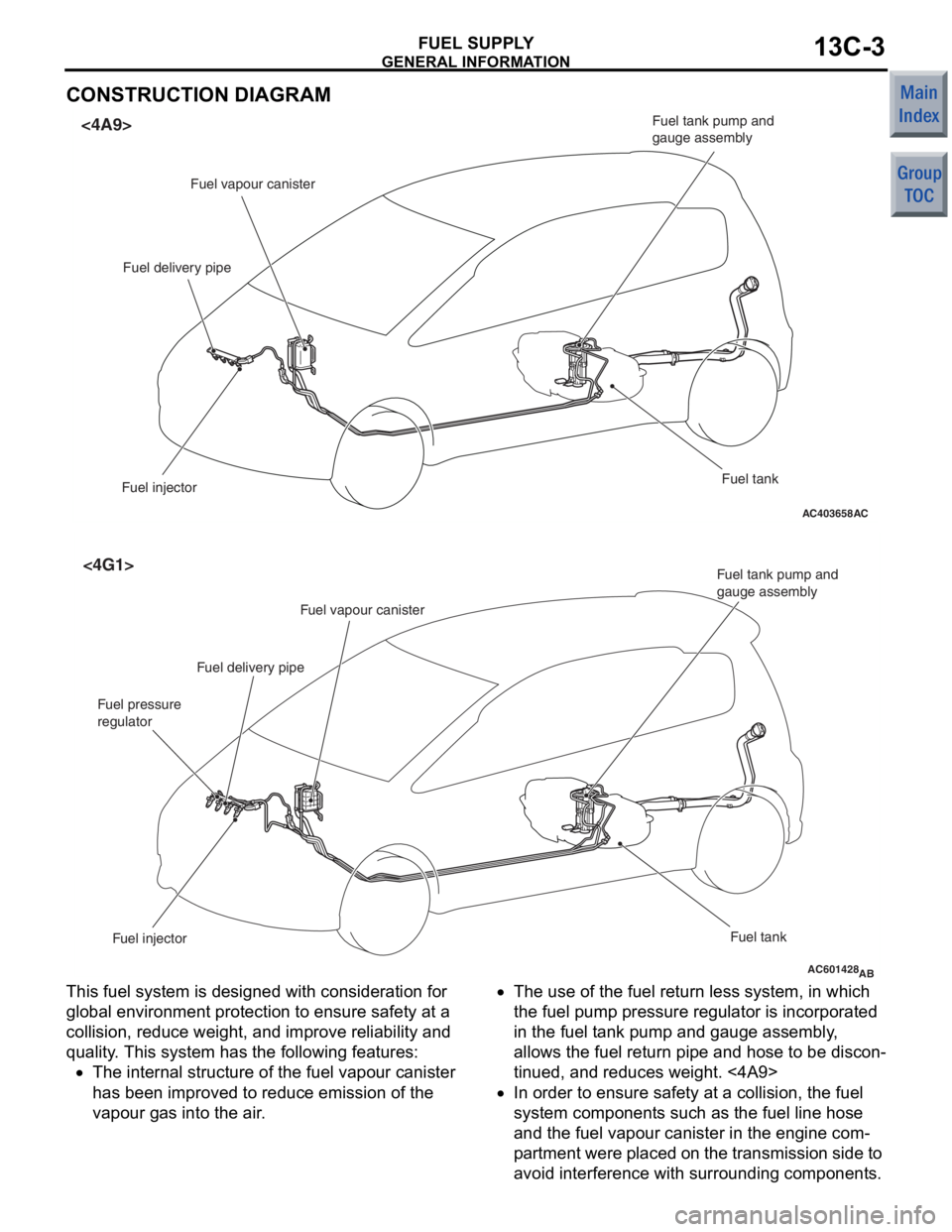
CONSTRUCTION DIAGRAM
AC403658AC
<4A9>
Fuel vapour canister
Fuel delivery pipe
Fuel injector Fuel tank
Fuel tank pump and
gauge assembly
AC601428AB
<4G1>
Fuel injector
Fuel tank
Fuel tank pump and
gauge assembly
Fuel vapour canister
Fuel delivery pipe
Fuel pressure
regulator
This fuel system is designed with considerat ion fo r
globa
l environ ment protection to ensure safety at a
collision,
reduce weigh t, and imp r ove re lia bility a nd
quality
. This system h a s th e following feature s :
•The intern al struct ure of t he fue l va pour canister
has bee
n improve d to re duce emission o f the
va
pour g a s into the air .
•The use of the fuel re turn less system, in wh ich
the
fuel pump pressure re gula t or is incorpora t ed
in
the fu el t ank pump and gauge assemb ly ,
allows t
he fue l return pipe and h o se to be d i scon
-
tinued, and red u ces weigh t. <4A9>
•In or der to ensu r e saf e ty a t a collision, the fuel
syst
em comp onent s such as the fue l line ho se
and
the fu el vapour canister in the engine com
-
pa rt men t were placed o n t he t r ansmissio n sid e to
avoid
interfe r ence with surroun ding componen t s .
Page 346 of 364

CONSTRUCTION DESCRIPTION
BASIC BRAKE SYSTEM35A-6
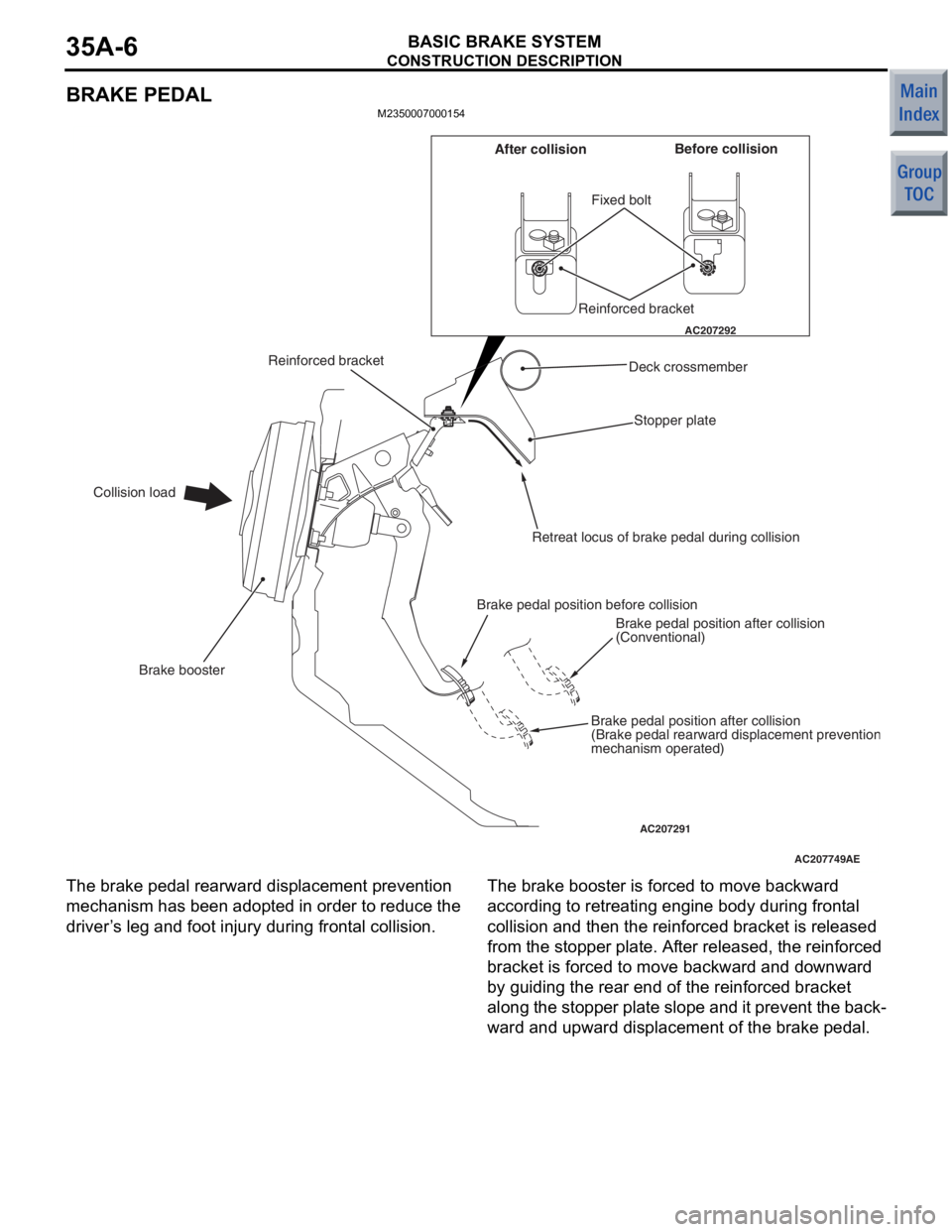
BRAKE PEDAL
M2350007000154
AC207749
AC207292
AC207291AE
Fixed bolt
Stopper plate
Brake booster
Collision load Before collision
After collision
Reinforced bracket
Deck crossmember
Retreat locus of brake pedal during collision
Brake pedal position before collision Brake pedal position after collision
(Conventional)
Brake pedal position after collision
(Brake pedal rearward displacement preventio
nmechanism operated)
Reinforced bracket
The bra
k e pe dal re arward displacement preve n tion
mechanism
has been adop ted in ord e r to reduce the
driver
’ s le g and foot injury during fron t a l co llisio n .The brak e bo oste r is force d to move backward
accordin
g to ret r eatin g engine bo dy d u ring front al
collision a
nd the n the r e info rced b r acket is release d
from
the stopper plat e. Af ter release d , the reinf o rced
bracket is forced to
move backward and do wn wa rd
by gu
iding the rear end of the reinf o rced bracket
along
the stoppe r plate slo pe and it preve n t the back
-
ward and upward displace ment of the b r ake pedal.
Page 350 of 364

CVT
CONTINUOUSLY VARIABLE TRANSMISSION (CVT)23-2
CVT
GENERAL INFORMATIONM2231000100165
The F1C1A transmission is adopted for the CVT.
This transmission is basically the same as conven
-
tional transmission.
The ATF warmer (ATF cooler) is adopted.
SPECIFICATIONS
ItemSpecification
Transmission modelF1C1A
Engine model4A91
Torque converterTy p e3-element, 1-stage, 2-phase type
Lock-upProvided
Stall torque ratio2.0
Transmission typeForward automatic continuously variable (steel belt type),
1st in reverse
Gear ratioForward2.319 − 0.445
Reverse2.588
ClutchA pair of multi-plate system
BrakeA pair of multi-plate system
Manual control systemP-R-N-D-Ds-L (smart shift)
FunctionVariable speed controlYe s
Line pressure controlYe s
Direct engagement controlYe s
N-D/N-R controlYe s
Shift pattern controlYe s
Self-diagnosisYe s
FailsafeYe s
Oil pumpTy p eExternal gear pump
ConfigurationBuilt-in (chain drive)
Control methodElectronic control (INVECS-III)
Transmission oilSpecified lubricantsDIA QUEEN ATF SP III
Quantity L8.1
Page 351 of 364

CVT
CONTINUOUSLY VARIABLE TRANSMISSION (CVT)23-3
ELECTRONIC CONTROL SYSTEM
EEPROM
M2231012000024
Because EEPROM has been used, even if the bat-
tery terminals or control unit connectors are discon-
nected, the necessary learned values are stored in
the engine-CVT-ECU to prevent a loss of shift qual
-
ity. (Initialisation is available by M.U.T.-III).
CONTROLLER AREA NETWORK (CAN)
COMMUNICATION
M2231017000018
CAN* communication has been adopted for commu-
nication with other ECUs in order to decrease the
number of wires and ensure information transmis
-
sion. For CVT control, the engine-CVT-ECU receives
the following signals.
CAN COMMUNICATION INPUT SIGNAL TABLE
Input signalTransmitter ECU
Average vehicle speed signal from drive wheelsABS-ECU
Motor current signalEPS-ECU
EPS warning lamp illumination request signal
Compressor signalMeter and A/C-ECU
NOTE: *: For more information about CAN (Control-
ler Area Network), refer to GROUP 54C P.54C-2.
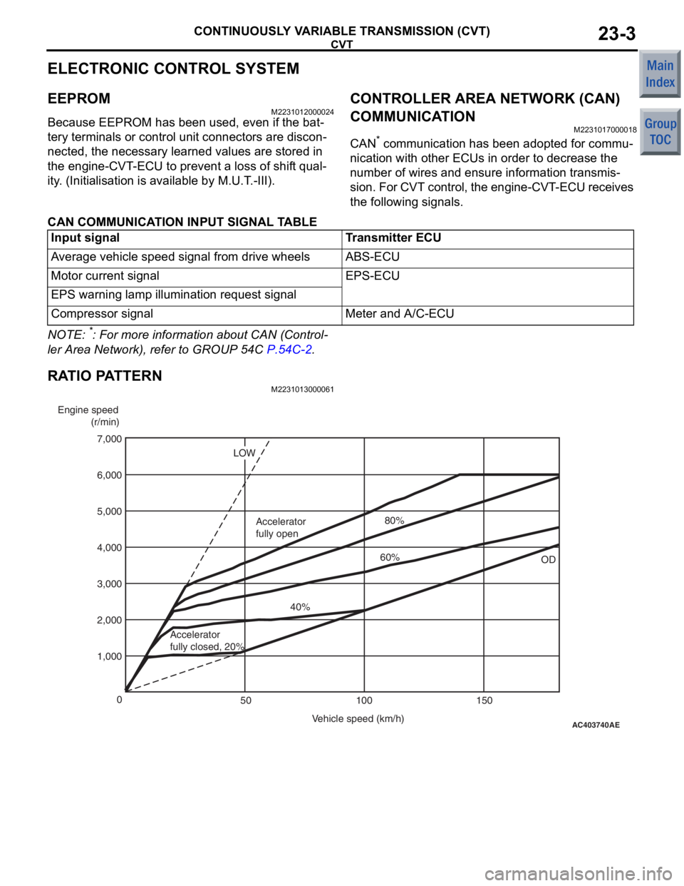
RATIO PATTERN
M2231013000061
AC403740
AE
Engine speed
(r/min)
Vehicle speed (km/h)
0
100 150
50
1,000 2,000 4,000
3,000 5,000
7,000
6,000
OD
LOW
Accelerator
fully closed, 20% 40%
Accelerator
fully open
60%80%