2006 MERCEDES-BENZ SPRINTER automatic gear sensor
[x] Cancel search: automatic gear sensorPage 863 of 2305

N2 and N3 Speed Sensors
The N2 and N3 Input Speed Sensors are two Hall-
effect speed sensors that are mounted internally in
the transmission and are used by the TCM to calcu-
late the transmission's input speed. Since the input
speed cannot be measured directly, two of the drive
elements are measured. Two input speed sensors
were required because both drive elements are not
active in all gears.
CAN C Bus Indirect Input Signals
A 2.5-volt bias (operating voltage) is present on the
CAN C bus any time the ignition switch is in the
RUN position. Both the TCM and the ABS apply this
bias. On this vehicle, the CAN C bus is used for mod-
ule data exchange only. The indirect inputs used on
the NAG1 electronic control system are:
²Wheel Speed Sensors.
²Brake Switch.
²Engine RPM.
²Engine Temperature.
²Cruise Control Status.
²Gear Limit Request.
²Throttle Position - 0% at idle, 100% at WOT. If
open, TCM assumes idle (0% throttle opening).
²Odometer Mileage
²Maximum Effective Torque.
²Engine in Limp-In Mode/Mileage Where DTC
Was Set.
BRAKE TRANSMISSION SHIFT INTERLOCK (BTSI)
The BTSI solenoid prevents shifting out of the
PARK position until the ignition key is in the RUN
position and the brake pedal is pressed. The TCM
controls the ground while the ignition switch supplies
power to the BTSI solenoid. The PCM monitors the
brake switch and broadcasts brake switch status
messages over the CAN C bus. If the park brake is
depressed and there is power (Run/Start) to SLA, the
BTSI solenoid deactivates.
SHIFT SCHEDULES
The basic shift schedule includes up and down-
shifts for all five gears. The TCM adapts the shift
program according to driving style, accelerator pedal
position and deviation of vehicle speed. Influencing
factors are:
²Road Conditions.
²Incline, Decline and Altitude.
²Trailer Operation, Loading.
²Engine Coolant Temperature.
²Cruise Control Operation.
²Sporty Driving Style.
²Low and High ATF Temperature.
Upshift
To :1-2 2-3 3-4 4-5
Activat-
ed By
Sole-
noid:1-2/4-5 2-3 3-4 1-2/4-5
Shift
Point
(at
35.2%
of throt-
tle)17.8
km/h
(11.6
mph)32.1
km/h
(19.95
mph)67.5
km/h
(41.94
mph)73.8
km/h
(45.86
mph)
Down-
shift
From:5-4 4-3 3-2 2-1
Activat-
ed By
Sole-
noid:1-2/4-5 3-4 2-3 1-2/4-5
Shift
Point55.7
km/h
(34.61
mph)40.5
km/h
(25.17
mph)24.4
km/h
(15.16
mph)15.1
km/h
(9.38
mph)
DOWNSHIFT SAFETY
Selector lever downshifts are not performed if inad-
missible high engine rpm is sensed.
ADAPTATION
To equalize tolerances and wear, an automatic
adaptation takes place for:
²Shift Time.
²Clutch Filling Time.
²Clutch Filling Pressure.
²Torque Converter Lock-Up Control.
Adaptation data may be stored permanently and to
some extent, can be diagnosed.
Driving Style Adaptation
The shift point is modified in steps based on the
information from the inputs. The control module
looks at inputs such as:
²vehicle acceleration and deceleration (calculated
by the TCM).
²rate of change as well as the position of the
throttle pedal (fuel injection information from the
ECM).
²lateral acceleration (calculated by the TCM).
²gear change frequency (how often the shift
occurs).
Based on how aggressive the driver is, the TCM
moves up the shift so that the present gear is held a
8E - 8 ELECTRONIC CONTROL MODULESVA
Page 912 of 2305

The heated seat system components operate on
battery current received through a fuse in the Fuse
Block on a fused ignition switch output (run-acc) cir-
cuit so that the system will only operate when the
ignition switch is in the On or Accessory positions.
The heated seat system will be turned Off automati-
cally whenever the ignition switch is turned to any
position except On or Accessory. Also, the heated seat
system will not operate when the surface tempera-
ture of the seat cushion cover at either heated seat
sensor is above the designed temperature set points
of the system.DIAGNOSIS AND TESTING - HEATED SEATS
Refer toWiringfor the appropriate wiring infor-
mation. The wiring information includes wiring dia-
grams, proper wire and connector repair procedures,
further details on wire harness routing and reten-
tion, as well as pin-out and location views for the
various wire harness connectors, splices and grounds.
HEATED SEAT SYSTEM DIAGNOSIS
CONDITION POSSIBLE CAUSES CORRECTION
NO HEATED SEAT SWITCH
ILLUMINATION WITH IGNI-
TION ON1. Faulty fuse. 1. Check heated seat fuse in Fuse Block. Re-
place fuse, if required.
2. Wiring faulty. 2. Check fused ignition switch output (run-acc)
circuit from heated seat switch connector to igni-
tion switch. Repair, if required.
3. Ground faulty. 3. Check for ground at heated seat switch con-
nector. Repair, if required.
4. Faulty switch. 4. Refer to Heated Seat Switch for the proper
switch diagnosis and testing procedures.
DRIVER HEATED SEAT
SWITCH
DESCRIPTION
The heated seat switches are located on the instru-
ment panel, in the accessory switch bezel. The two,
momentary rocker type switches provide a signal to
the Heated Seat Relay through separate hard wired
circuits. Each switch contains two light emitting
diodes (LED), one for each High and Low setting to
let the occupant know that the seat heater system is
on.
The heated seat switches and their LED's cannot
be repaired. If either switch is faulty or damaged the
entire switch must be replaced.
OPERATION
There are three modes that can be selected with
each of the heated seat switches: Off, Low, and High.
When the top of the switch rocker is depressed, the
low mode is selected and the low mode LED indicator
illuminates. Depressing the top of the switch rocker a
second time will turn the heated seat to Off. This
same process is repeated for High heat setting. The
heated seats will automatically return to the Off
mode anytime the vehicle ignition switch is turned
Off.Both switches provide separate hard wire inputs to
the Heated Seat Relay to indicate the selected mode.
The Heated Seat Relay responds to the heated seat
switch messages by controlling the output to the seat
heater elements of the selected seat.
DIAGNOSIS AND TESTING - DRIVER HEATED
SEAT SWITCH
For circuit description and diagrams, refer toWir-
ing.
(1) Inspect the Heated Seat Switches for apparent
damage or sticking/binding and replace if required.
Refer to Heated Seat Switch Removal and Installa-
tion in this section.
(2) Replace the heated seat switch with a known
good unit and retest the heated seat system.
REMOVAL
(1) Disconnect and isolate the negative battery
cable.
(2) Remove the gear selector bezel trim. Refer to
the Body section for the procedure.
(3) Remove the storage bin. Refer to the Body sec-
tion for the procedure.
(4) Remove the switch bezel retaining screw and
remove the switch bezel from the instrument panel.
Refer to the Body section for the procedure.
(5) Disconnect electrical connections.
VAHEATED SEATS 8G - 11
Page 925 of 2305

INDICATORS
Indicators are located in various positions within
the EMIC and are all connected to the EMIC elec-
tronic circuit board. The ambient temperature indica-
tor (optional), brake indicator, brake wear indicator,
charging indicator, coolant low indicator, high beam
indicator, low fuel indicator, park brake indicator,
seatbelt indicator, turn signal indicators, and washer
fluid indicator operate based upon hard wired inputs
to the EMIC. The airbag (SRS) indicator is normally
controlled by a hard wired input from the Airbag
Control Module (ACM); however, if the EMIC sees an
abnormal or no input from the ACM, it will automat-
ically turn the airbag indicator On until the hard
wired input from the ACM has been restored. The
Malfunction Indicator Lamp (MIL) is normally con-
trolled by CAN data bus messages from the Engine
Control Module (ECM); however, if the EMIC loses
CAN data bus communication, the EMIC circuitry
will automatically turn the MIL on until CAN data
bus communication is restored. The EMIC uses CAN
data bus messages from the ECM, the ACM, and the
Controller Antilock Brake to control all of the
remaining indicators.
The various EMIC indicators are controlled by dif-
ferent strategies; some receive battery feed from the
EMIC circuitry and have a switched ground, while
others are grounded through the EMIC circuitry and
have a switched battery feed. However, all indicators
are completely controlled by the EMIC microproces-
sor based upon various hard wired and electronic
message inputs. Except for the indications provided
by the multi-function indicator Liquid Crystal Dis-
play (LCD) unit, all indicators are illuminated at a
fixed intensity, which is not affected by the selected
illumination intensity of the EMIC general illumina-
tion lamps.
The hard wired indicator inputs may be diagnosed
using conventional diagnostic methods. However,
proper testing of the EMIC circuitry and the CAN
bus message controlled indicators requires the use of
a diagnostic scan tool. Refer to the appropriate diag-
nostic information. Specific details of the operation
for each indicator may be found elsewhere in this
service information.
CLUSTER ILLUMINATION
The EMIC has several general illumination lamps
that are illuminated when the exterior lighting is
turned on with the multi-function switch. The illumi-
nation intensity of these lamps is adjusted by a dim-
ming level input received from the multi-function
indicator ª+º (plus) and ª±º (minus) switch push but-
tons that extend through the lower edge of the clus-
ter lens below the right end of the multi-function
indicator. When the exterior lighting is turned Off,
the display is illuminated at maximum brightness.
When the exterior lighting is turned On and thetransmission gear selector is in the Park position,
depressing the plus switch push button brightens the
display lighting, and depressing the minus switch
push button dims the display lighting. The EMIC
also provides a Pulse-Width Modulated (PWM) panel
lamps dimmer output that can be used to synchro-
nize the illumination lighting levels of external illu-
mination lamps (up to about 23 to 30 watts) with
that of the EMIC.
The hard wired multi-function switch input and
the EMIC panel lamps dimmer output may be diag-
nosed using conventional diagnostic methods. How-
ever, proper testing of the PWM control of the EMIC
and the electronic dimming level inputs from the
multi-function indicator push buttons requires the
use of a diagnostic scan tool. Refer to the appropriate
diagnostic information.
INPUT AND OUTPUT CIRCUITS
HARD WIRED INPUTS
The hard wired inputs to the EMIC include the fol-
lowing:
NOTE: Final approved circuit names were not yet
available at the time this information was compiled.
²Airbag Indicator Driver
²Ambient Temperature Sensor Signal
(Optional)
²Brake Wear Indicator Sense
²Charging Indicator Driver
²Coolant Level Switch Sense
²Front Door Jamb Switch Sense
²Fuel Level Sensor Signal
²Fused B(+)
²Fused Ignition Switch Output
²High Beam Indicator Driver
²Key-In Ignition Switch Sense
²Left Turn Signal
²Park Brake Switch Sense
²Right Turn Signal
²Seat Belt Switch Sense
²Washer Fluid Switch Sense (Optional)
Refer to the appropriate wiring information for
additional details.
HARD WIRED OUTPUTS
The hard wired outputs of the EMIC include the
following:
²Engine Running Relay Control
²Panel Lamps Driver
Refer to the appropriate wiring information for
additional details.
8J - 6 INSTRUMENT CLUSTERVA
Page 937 of 2305

circuit board. The fuel gauge is serviced as a unit
with the instrument cluster.
OPERATION
The fuel gauge gives an indication to the vehicle
operator of the level of fuel in the fuel tank. This
gauge is controlled by the instrument cluster circuit
board based upon cluster programming and a hard
wired input received by the cluster from the fuel
level sensor in the fuel tank. The fuel gauge is an air
core magnetic unit that receives battery current on
the instrument cluster electronic circuit board when
the instrument cluster detects that the ignition
switch is in the On position. The cluster is pro-
grammed to move the gauge needle back to the low
end of the scale after the ignition switch is turned to
the Off position. The instrument cluster circuitry
controls the gauge needle position and provides the
following features:
²Fuel Level Sensor Input (At Ignition On)-
When the cluster detects the ignition switch has been
turned to the On position, the cluster moves the
gauge needle to the proper relative position on the
gauge scale as signaled by the fuel level sensor with-
out any electronic damping.
²Fuel Level Sensor Input (After Ignition On)
- After the ignition switch has been turned to the On
position, the cluster applies an algorithm to the input
from the fuel level sensor to electronically dampen
gauge needle movement against the negative effect
that fuel sloshing within the fuel tank can have on
accurate gauge readings.
²Fuel Level Sensor Input Open- If the fuel
level sensor input to the instrument cluster is an
open circuit, the cluster will move the fuel gauge nee-
dle to the ªEº (Empty) position on the gauge scale,
but the low fuel indicator will not be illuminated.
The fuel level sensor in the fuel tank provides a
hard wired input to the instrument cluster circuitry
through the fuel level sense circuit. The fuel level
sensor is a potentiometer that changes resistance
according to the fuel level. The instrument cluster
applies a fuel tank characteristic curve and fuel tank
reserve valve setting to the fuel level sensor input,
which must be configured when the cluster is initial-
ized. These characteristics determine the algorithm
the cluster uses to display the fuel level data on the
fuel gauge and the control for the low fuel warning
indicator. As the fuel level decreases, the resistance
through the fuel level sensor increases. The fuel level
sensor and the fuel level sense circuit to the instru-
ment cluster can be diagnosed using conventional
diagnostic tools and methods. For proper diagnosis of
the instrument cluster circuitry that controls the fuel
gauge, a diagnostic scan tool is required. Refer to the
appropriate diagnostic information.
GEAR SELECTOR INDICATOR
DESCRIPTION
An electronic automatic transmission gear selector
indicator is standard equipment on all instrument
clusters. The gear selector indicator information is
displayed in the center of the multi-function indicator
Liquid Crystal Display (LCD) located near the lower
edge of the instrument cluster, directly below the
speedometer. The gear selector indicator displays the
following characters as they are selected: ªP,º ªR,º
ªN,º ªD,º ª4,º ª3,º ª2,º and ª1.º Respectively, these
characters represent the currently selected park,
reverse, neutral, drive, fourth gear, third gear, second
gear, and first gear positions of the transmission gear
selector lever on the instrument panel.
The indications of the gear selector indicator are
not visible unless the multi-function indicator LCD is
illuminated and the engine is running. When illumi-
nated, each indication appears as a dark character
silhouetted against an amber field. When the exterior
lighting is turned Off, the display is illuminated at
maximum brightness. When the exterior lighting is
turned On, the display illumination level can be
adjusted in concert with the cluster general illumina-
tion lighting using the ª+º (plus) and ª2º (minus)
multi-function indicator push buttons. The gear
selector indicator is serviced as a unit with the
instrument cluster.
OPERATION
The electronic gear selector indicator gives an indi-
cation to the vehicle operator of the transmission
gear that is currently selected with the automatic
transmission gear selector lever. This indicator is
controlled by the instrument cluster circuit board
based upon cluster programming and electronic mes-
sages received from the Transmission Control Module
(TCM) over the Controller Area Network (CAN) data
bus. The gear selector indicator information is dis-
played by the multi-function indicator Liquid Crystal
Display (LCD) unit on the instrument cluster elec-
tronic circuit board. The multi-function indicator
LCD is completely controlled by the instrument clus-
ter logic circuit, and that logic will only allow the
gear selector indicator information to be displayed
when the instrument cluster detects that the ignition
switch is in the On position. Therefore, the gear
selector indicator will always be off when the ignition
switch is in any position except On.
The TCM continually monitors the transmission
range sensor, then sends the proper gear selector
indicator position messages to the instrument cluster.
For proper diagnosis of the transmission range sen-
sor, the TCM, the CAN data bus, or the electronic
message inputs to the instrument cluster that control
the gear selector indicator, a diagnostic scan tool is
8J - 18 INSTRUMENT CLUSTERVA
Page 1585 of 2305
(11) Install the torque converter access plate. Refer
to (Refer to 21 - TRANSMISSION/TRANSAXLE/AU-
TOMATIC - NAG1 - INSTALLATION) for correct
sequence and torque specification.
(12) Install the transmission cooler lines to trans-
mission. (Refer to 21 - TRANSMISSION/TRANS-
AXLE/AUTOMATIC - NAG1 - INSTALLATION) for
correct sequence and torque specification.
(13) Connect the engine valley drain hose to the
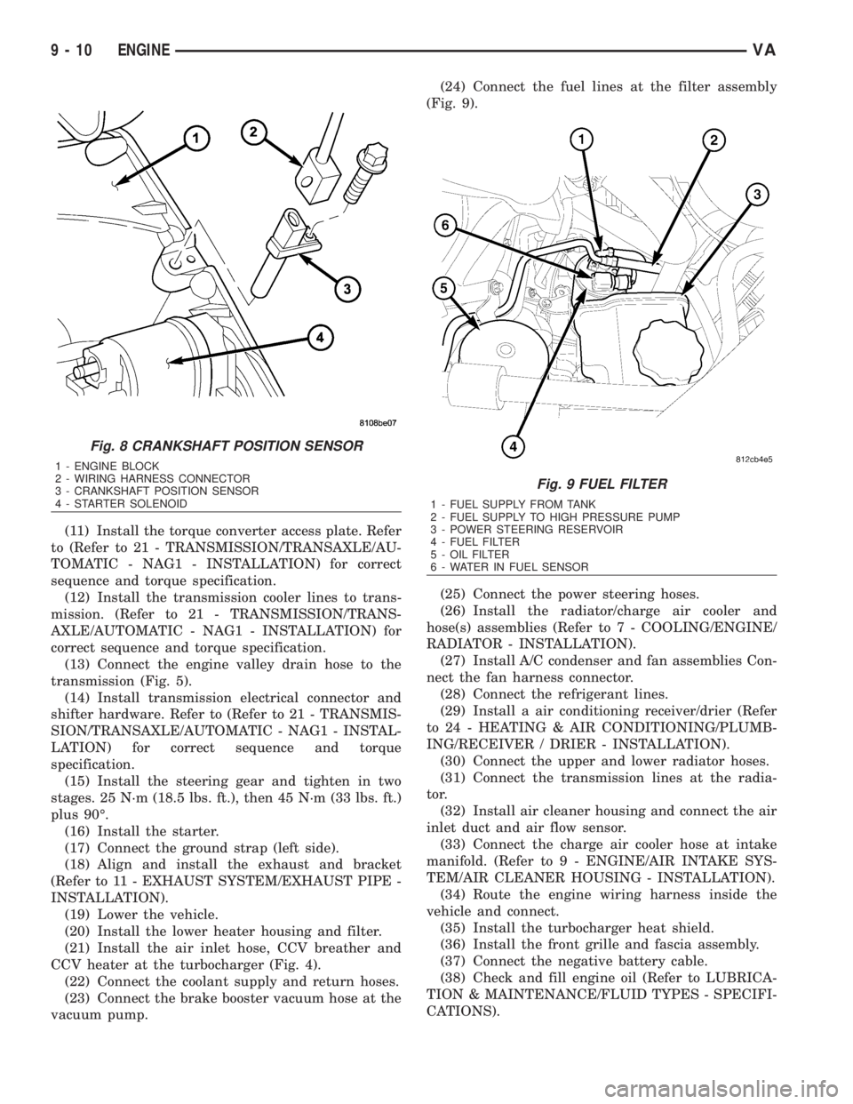
transmission (Fig. 5).
(14) Install transmission electrical connector and
shifter hardware. Refer to (Refer to 21 - TRANSMIS-
SION/TRANSAXLE/AUTOMATIC - NAG1 - INSTAL-
LATION) for correct sequence and torque
specification.
(15) Install the steering gear and tighten in two
stages. 25 N´m (18.5 lbs. ft.), then 45 N´m (33 lbs. ft.)
plus 90É.
(16) Install the starter.
(17) Connect the ground strap (left side).
(18) Align and install the exhaust and bracket
(Refer to 11 - EXHAUST SYSTEM/EXHAUST PIPE -
INSTALLATION).
(19) Lower the vehicle.
(20) Install the lower heater housing and filter.
(21) Install the air inlet hose, CCV breather and
CCV heater at the turbocharger (Fig. 4).
(22) Connect the coolant supply and return hoses.
(23) Connect the brake booster vacuum hose at the
vacuum pump.(24) Connect the fuel lines at the filter assembly
(Fig. 9).
(25) Connect the power steering hoses.
(26) Install the radiator/charge air cooler and
hose(s) assemblies (Refer to 7 - COOLING/ENGINE/
RADIATOR - INSTALLATION).
(27) Install A/C condenser and fan assemblies Con-
nect the fan harness connector.
(28) Connect the refrigerant lines.
(29) Install a air conditioning receiver/drier (Refer
to 24 - HEATING & AIR CONDITIONING/PLUMB-
ING/RECEIVER / DRIER - INSTALLATION).
(30) Connect the upper and lower radiator hoses.
(31) Connect the transmission lines at the radia-
tor.
(32) Install air cleaner housing and connect the air
inlet duct and air flow sensor.
(33) Connect the charge air cooler hose at intake
manifold. (Refer to 9 - ENGINE/AIR INTAKE SYS-
TEM/AIR CLEANER HOUSING - INSTALLATION).
(34) Route the engine wiring harness inside the
vehicle and connect.
(35) Install the turbocharger heat shield.
(36) Install the front grille and fascia assembly.
(37) Connect the negative battery cable.
(38) Check and fill engine oil (Refer to LUBRICA-
TION & MAINTENANCE/FLUID TYPES - SPECIFI-
CATIONS).
Fig. 8 CRANKSHAFT POSITION SENSOR
1 - ENGINE BLOCK
2 - WIRING HARNESS CONNECTOR
3 - CRANKSHAFT POSITION SENSOR
4 - STARTER SOLENOID
Fig. 9 FUEL FILTER
1 - FUEL SUPPLY FROM TANK
2 - FUEL SUPPLY TO HIGH PRESSURE PUMP
3 - POWER STEERING RESERVOIR
4 - FUEL FILTER
5 - OIL FILTER
6 - WATER IN FUEL SENSOR
9 - 10 ENGINEVA
Page 1744 of 2305
TRANSMISSION
TABLE OF CONTENTS
page
AUTOMATIC TRANSMISSION NAG1 - SERVICE
INFORMATION............................1
AUTOMATIC TRANSMISSION NAG1 - SERVICE
INFORMATION
TABLE OF CONTENTS
page page
AUTOMATIC TRANSMISSION NAG1 - SERVICE
INFORMATION
DESCRIPTION..........................3
OPERATION............................4
DIAGNOSIS AND TESTING
AUTOMATIC TRANSMISSION............39
PRELIMINARY........................39
ROAD TESTING......................39
AUTOMATIC TRANSMISSION............40
STANDARD PROCEDURE - ALUMINUM
THREAD REPAIR......................42
REMOVAL.............................42
DISASSEMBLY.........................46
ASSEMBLY............................52
INSTALLATION.........................60
SCHEMATICS AND DIAGRAMS............65
SPECIFICATIONS - NAG1 AUTOMATIC
TRANSMISSION......................86
SPECIAL TOOLS - AUTOMATIC
TRANSMISSION - NAG1................87
INPUT CLUTCHES
DESCRIPTION.........................90
OPERATION...........................91
INPUT CLUTCH K1
DISASSEMBLY.........................92
ASSEMBLY............................94
INPUT CLUTCH K2
DISASSEMBLY.........................97
ASSEMBLY............................99
INPUT CLUTCH K3
DISASSEMBLY........................102
ASSEMBLY...........................103
ELECTROHYDRAULIC UNIT
DESCRIPTION........................105
OPERATION..........................112
REMOVAL............................120
DISASSEMBLY........................121
ASSEMBLY...........................125INSTALLATION........................129
FLUID AND FILTER
DESCRIPTION........................131
OPERATION..........................131
DIAGNOSIS AND TESTING
EFFECTS OF INCORRECT FLUID LEVEL . . 131
CAUSES OF BURNT FLUID.............132
FLUID CONTAMINATION...............132
STANDARD PROCEDURE
CHECK OIL LEVEL...................132
TRANSMISSION FILL.................133
FLUID/FILTER SERVICE...............134
FREEWHEELING CLUTCH
DESCRIPTION........................135
OPERATION..........................135
DISASSEMBLY........................136
ASSEMBLY...........................138
GEARSHIFT CABLE
DIAGNOSIS AND TESTING
GEARSHIFT CABLE..................138
REMOVAL............................139
INSTALLATION........................140
HOLDING CLUTCHES
DESCRIPTION........................141
OPERATION..........................142
HOLDING CLUTCH B1
DISASSEMBLY........................143
ASSEMBLY...........................145
HOLDING CLUTCH B2
DISASSEMBLY........................148
ASSEMBLY...........................150
INPUT SPEED SENSORS
DESCRIPTION........................153
OPERATION..........................154
OIL PUMP
DESCRIPTION........................154
OPERATION..........................154
DISASSEMBLY........................155
VATRANSMISSION 21 - 1
Page 1745 of 2305
INSPECTION.........................155
ASSEMBLY...........................156
OUTPUT SHAFT BEARING
REMOVAL............................156
INSTALLATION........................158
OUTPUT SHAFT SEAL
REMOVAL............................159
INSTALLATION........................159
PARK LOCK CABLE
REMOVAL............................160
INSTALLATION........................161
PISTONS
DESCRIPTION........................163
OPERATION..........................163
PLANETARY GEARTRAIN
DESCRIPTION........................164
OPERATION..........................165
DISASSEMBLY........................166
ASSEMBLY...........................167
SHIFT MECHANISM
DESCRIPTION........................168
OPERATION..........................168REMOVAL............................169
INSTALLATION........................170
SOLENOID
DESCRIPTION........................171
OPERATION..........................174
TEMPERATURE SENSOR/PARK-NEUTRAL
CONTACT
DESCRIPTION
PARK/NEUTRAL CONTACT.............176
TRANSMISSION TEMPERATURE SENSOR . 176
OPERATION
PARK/NEUTRAL CONTACT.............177
TRANSMISSION TEMPERATURE SENSOR . 177
TORQUE CONVERTER
DESCRIPTION........................178
OPERATION..........................182
REMOVAL............................183
INSTALLATION........................184
TORQUE CONVERTER HUB SEAL
REMOVAL............................184
INSTALLATION........................184
21 - 2 AUTOMATIC TRANSMISSION NAG1 - SERVICE INFORMATIONVA
Page 1785 of 2305
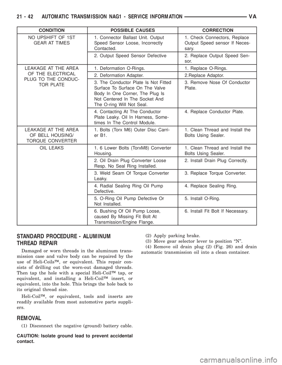
CONDITION POSSIBLE CAUSES CORRECTION
NO UPSHIFT OF 1ST
GEAR AT TIMES1. Connector Ballast Unit. Output
Speed Sensor Loose, Incorrectly
Contacted.1. Check Connectors, Replace
Output Speed sensor If Neces-
sary.
2. Output Speed Sensor Defective 2. Replace Output Speed Sen-
sor.
LEAKAGE AT THE AREA
OF THE ELECTRICAL
PLUG TO THE CONDUC-
TOR PLATE1. Deformation O-Rings. 1. Replace O-Rings.
2. Deformation Adapter. 2.Replace Adaptor.
3. The Conductor Plate Is Not Fitted
Surface To Surface On The Valve
Body In One Corner, The Plug Is
Not Centered In The Socket And
The O-ring Will Not Seal.3. Remove Nose Of Conductor
Plate.
4. Contacting At The Conductor
Plate Leaky. Oil In Harness, Some-
times In The Control Module.4. Replace Conductor Plate.
LEAKAGE AT THE AREA
OF BELL HOUSING/
TORQUE CONVERTER1. Bolts (Torx M6) Outer Disc Carri-
er B1.1. Clean Thread and Install the
Bolts Using Sealer.
OIL LEAKS 1. 6 Lower Bolts (TorxM8) Converter
Housing.1. Clean Thread and Install the
Bolts Using Sealer.
2. Oil Drain Plug Converter Loose
Resp. No Seal Ring Installed.2. Install Drain Plug Correctly.
3. Weld Seam Of Torque Converter
Leaky.3. Replace Torque Converter.
4. Radial Sealing Ring Oil Pump
Defective.4. Replace Sealing Ring.
5. O-Ring Oil Pump Defective Or
Not Installed.5. Install O-Ring.
6. Bushing Of Oil Pump Loose,
caused By Missing Fit Bolt At
Transmission/Engine Flange.6. Install Fit Bolt If Necessary.
STANDARD PROCEDURE - ALUMINUM
THREAD REPAIR
Damaged or worn threads in the aluminum trans-
mission case and valve body can be repaired by the
use of Heli-CoilsŸ, or equivalent. This repair con-
sists of drilling out the worn-out damaged threads.
Then tap the hole with a special Heli-CoilŸ tap, or
equivalent, and installing a Heli-CoilŸ insert, or
equivalent, into the hole. This brings the hole back to
its original thread size.
Heli-CoilŸ, or equivalent, tools and inserts are
readily available from most automotive parts suppli-
ers.
REMOVAL
(1) Disconnect the negative (ground) battery cable.
CAUTION: Isolate ground lead to prevent accidental
contact.(2) Apply parking brake.
(3) Move gear selector lever to position ªNº.
(4) Remove oil drain plug (2) (Fig. 26) and drain
automatic transmission oil into a clean container.
21 - 42 AUTOMATIC TRANSMISSION NAG1 - SERVICE INFORMATIONVA