2006 MERCEDES-BENZ SPRINTER warning light
[x] Cancel search: warning lightPage 2073 of 2305
motor, while relay 2 when activated, sends power
directly to the blower motor.
The rear blower motor switch cannot be repaired
and, if faulty or damaged, it must be replaced.
DIAGNOSIS AND TESTING
REAR BLOWER MOTOR SWITCH
Before testing the rear blower motor switch, verify
that the front A/C system is functional by performing
the ATC Fuction Test using the DRBIIItscan tool.
Use a volt/ohmmeter to test the rear blower motor
switch. For circuit descriptions and diagrams, refer
to the appropriate wiring information. The wiring
information includes wiring diagrams, proper wire
and connector repair procedures, details of wire har-
ness routing and retention, connector pin-out infor-
mation and location views for the various wire
harness connectors, splices and grounds.
WARNING: To avoid personal injury or death, on
vehicles equipped with airbags, disable the supple-
mental restraint system before attempting any
steering wheel, steering column, airbag, seat belt
tensioner, impact sensor, or instrument panel com-
ponent diagnosis or service. Disconnect and isolate
the battery negative (ground) cable, then wait two
minutes for the system capacitor to discharge
before performing further diagnosis or service. This
is the only sure way to disable the supplemental
restraint system. Failure to take the proper precau-
tions could result in accidental airbag deployment.
(1) Disconnect and isolate the battery negative
cable.
(2) Unplug the wire harness connector from the
rear blower motor switch.
(3) Check for continuity between terminal 10 and
terminals 1, 7 and 4 of the blower motor switch. In
all instances, there should be continuity.
NOTE: To check the switch's internal circuits, con-
nect the negative lead of the ohmmeter to terminal
10 and the positive ohmmeter lead to terminals 1, 7
and 4. To check the switch's integral light emitting
diodes, reverse the ohmmeter leads.
(4) Check for continuity between the rear blower
motor switch terminals 3 and 7 as you move the
blower motor switch to each of the two speed posi-
tions, and the Off position. There should be continu-
ity in only one blower motor switch speed position.
(5) Check for continuity between the rear blower
motor switch terminals 4 and 8 as you move the
blower motor switch to each of the two speed posi-
tions, and the Off position. There should be continu-ity in only the other blower motor switch speed
position.
(6) If OK, test and repair the rear blower motor
switch wire harness circuits. If not OK, replace the
faulty rear blower motor switch.
REMOVAL
WARNING: To avoid personal injury or death, on
vehicles equipped with airbags, disable the supple-
mental restraint system before attempting any
steering wheel, steering column, airbag, seat belt
tensioner, impact sensor, or instrument panel com-
ponent diagnosis or service. Disconnect and isolate
the battery negative (ground) cable, then wait two
minutes for the system capacitor to discharge
before performing further diagnosis or service. This
is the only sure way to disable the supplemental
restraint system. Failure to take the proper precau-
tions could result in accidental airbag deployment.
NOTE: The rear A/C blower motor switch is used on
vehicles with the optional rear A/C system.
(1) Disconnect and isolate the negative battery
cable.
(2) Remove the accessory switch panel from the
instrument panel (Refer to 23 - BODY/INSTRU-
MENT PANEL/ACCESSORY SWITCH BEZEL -
REMOVAL).
(3) Disconnect the wire harness connector from the
rear A/C blower motor switch (Fig. 14).
(4) Disengage the retaining tabs and remove the
rear A/C blower motor switch from the accessory
switch panel.
24 - 36 CONTROLS - REARVA
Page 2076 of 2305
rear A/C control module. The temperature of the cir-
culated internal air of the rear compartment is mea-
sured by a temperature sensor located in the rear
evaporator unit. The value of the temperature sensor
is compared in the rear A/C control module with an
adjusted value at the rear A/C temperature control.
The rear A/C temperature control cannot be
repaired and, if faulty or damaged, it must be
replaced.
DIAGNOSIS AND TESTING
REARA/CTEMPERATURE CONTROL
Before testing the rear A/C temperature control,
verify that the front A/C system is operating correctly
by performing the ATC Function Test using the
DRBIIItscan tool. Use a volt/ohmmeter to test the
control. For circuit descriptions and diagrams, refer
to the appropriate wiring information. The wiring
information includes wiring diagrams, proper wire
and connector repair procedures, details of wire har-
ness routing and retention, connector pin-out infor-
mation and location views for the various wire
harness connectors, splices and grounds.
WARNING: To avoid personal injury or death, on
vehicles equipped with airbags, disable the supple-
mental restraint system before attempting any
steering wheel, steering column, airbag, seat belt
tensioner, impact sensor, or instrument panel com-
ponent diagnosis or service. Disconnect and isolate
the battery negative (ground) cable, then wait two
minutes for the system capacitor to discharge
before performing further diagnosis or service. This
is the only sure way to disable the supplemental
restraint system. Failure to take the proper precau-
tions could result in accidental airbag deployment.
(1) Disconnect and isolate the battery negative
cable.
(2) Unplug the wire harness connector from the
rear A/C temperature control.
(3) Check for continuity between terminal 9 and
terminals 3 and 5 of the A/C temperature control. In
all instances, there should be continuity.
NOTE: To check the switch's internal circuits, con-
nect the positive lead of the ohmmeter to terminal 9
and the negative lead to terminals 3 and 5. To
check the switches integral light emitting diode,
reverse the ohmmeter leads.
(4) Check for resistance between terminal 3 and 5
of the A/C temperature control as you move the con-
trol to each temperature position. Resistance should
be present and should change for each position.(5) If OK, test and repair the rear A/C tempera-
ture control wire harness circuits. If not OK, replace
the faulty rear A/C temperature control.
REMOVAL
WARNING: To avoid personal injury or death, on
vehicles equipped with airbags, disable the supple-
mental restraint system before attempting any
steering wheel, steering column, airbag, seat belt
tensioner, impact sensor, or instrument panel com-
ponent diagnosis or service. Disconnect and isolate
the battery negative (ground) cable, then wait two
minutes for the system capacitor to discharge
before performing further diagnosis or service. This
is the only sure way to disable the supplemental
restraint system. Failure to take the proper precau-
tions could result in accidental airbag deployment.
NOTE: The rear A/C temperature control is used
only on models with the optional rear A/C unit.
(1) Disconnect and isolate the negative battery
cable.
(2) Remove the accessory switch panel from the
instrument panel (Refer to 23 - BODY/INSTRU-
MENT PANEL/ACCESSORY SWITCH BEZEL -
REMOVAL).
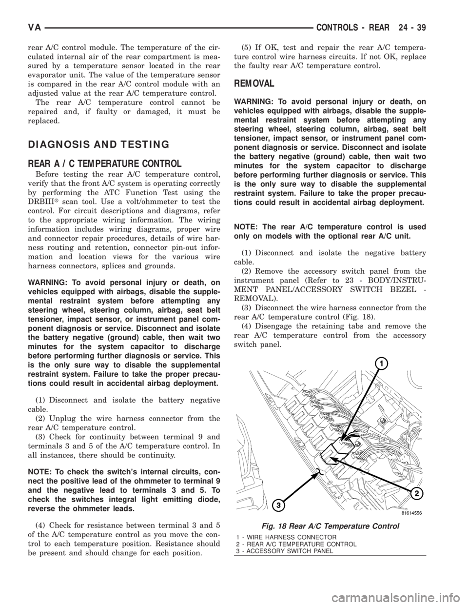
(3) Disconnect the wire harness connector from the
rear A/C temperature control (Fig. 18).
(4) Disengage the retaining tabs and remove the
rear A/C temperature control from the accessory
switch panel.
Fig. 18 Rear A/C Temperature Control
1 - WIRE HARNESS CONNECTOR
2 - REAR A/C TEMPERATURE CONTROL
3 - ACCESSORY SWITCH PANEL
VACONTROLS - REAR 24 - 39
Page 2092 of 2305
(15) Reconnect the negative battery cable.
(16) Evacuate the rear refrigerant system (Refer to
24 - HEATING & AIR CONDITIONING/PLUMBING
- STANDARD PROCEDURE - REFRIGERANT SYS-
TEM EVACUATE).
(17) Charge the rear refrigerant system (Refer to
24 - HEATING & AIR CONDITIONING/PLUMBING
- STANDARD PROCEDURE - REFRIGERANT SYS-
TEM CHARGE).
(18) Install the rear air filter (Refer to 24 - HEAT-
ING & AIR CONDITIONING/DISTRIBUTION -
REAR/AIR FILTER - INSTALLATION).
(19) Install the cover onto the rear A/C condenser
housing (Refer to 24 - HEATING & AIR CONDI-
TIONING/DISTRIBUTION - REAR/A/C CON-
DENSER COVER - INSTALLATION).
A/CEVAPORATOR COVER
REMOVAL
(1) Disconnect and isolate the negative battery
cable.
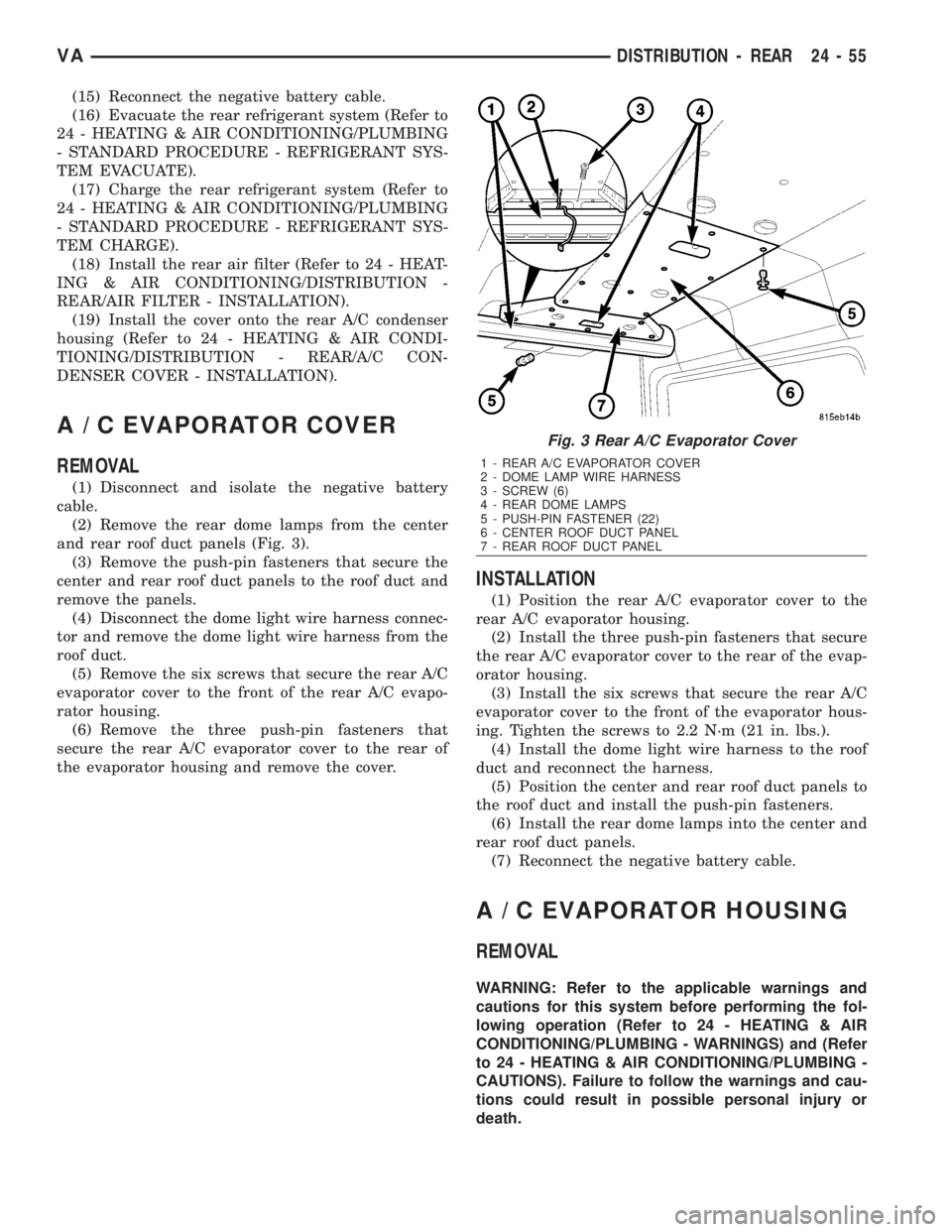
(2) Remove the rear dome lamps from the center
and rear roof duct panels (Fig. 3).
(3) Remove the push-pin fasteners that secure the
center and rear roof duct panels to the roof duct and
remove the panels.
(4) Disconnect the dome light wire harness connec-
tor and remove the dome light wire harness from the
roof duct.
(5) Remove the six screws that secure the rear A/C
evaporator cover to the front of the rear A/C evapo-
rator housing.
(6) Remove the three push-pin fasteners that
secure the rear A/C evaporator cover to the rear of
the evaporator housing and remove the cover.
INSTALLATION
(1) Position the rear A/C evaporator cover to the
rear A/C evaporator housing.
(2) Install the three push-pin fasteners that secure
the rear A/C evaporator cover to the rear of the evap-
orator housing.
(3) Install the six screws that secure the rear A/C
evaporator cover to the front of the evaporator hous-
ing. Tighten the screws to 2.2 N´m (21 in. lbs.).
(4) Install the dome light wire harness to the roof
duct and reconnect the harness.
(5) Position the center and rear roof duct panels to
the roof duct and install the push-pin fasteners.
(6) Install the rear dome lamps into the center and
rear roof duct panels.
(7) Reconnect the negative battery cable.
A/CEVAPORATOR HOUSING
REMOVAL
WARNING: Refer to the applicable warnings and
cautions for this system before performing the fol-
lowing operation (Refer to 24 - HEATING & AIR
CONDITIONING/PLUMBING - WARNINGS) and (Refer
to 24 - HEATING & AIR CONDITIONING/PLUMBING -
CAUTIONS). Failure to follow the warnings and cau-
tions could result in possible personal injury or
death.
Fig. 3 Rear A/C Evaporator Cover
1 - REAR A/C EVAPORATOR COVER
2 - DOME LAMP WIRE HARNESS
3 - SCREW (6)
4 - REAR DOME LAMPS
5 - PUSH-PIN FASTENER (22)
6 - CENTER ROOF DUCT PANEL
7 - REAR ROOF DUCT PANEL
VADISTRIBUTION - REAR 24 - 55
Page 2098 of 2305
REAR REFRIGERANT RESERVOIR
REMOVAL.............................95
INSTALLATION.........................95
REAR SUCTION LINE
DESCRIPTION.........................96
REMOVAL.............................96
INSTALLATION.........................98
REFRIGERANT LINE COUPLER
DESCRIPTION.........................98OPERATION...........................98
REMOVAL.............................99
INSTALLATION.........................99
UNDERBODY LINES
REMOVAL............................100
INSTALLATION........................102
PLUMBING
DESCRIPTION
The refrigerant lines and hoses are used to carry
the refrigerant between the various air conditioning
system components. A barrier hose design with a
nylon tube, which is sandwiched between rubber lay-
ers, is used for the R-134a air conditioning system on
this vehicle. This nylon tube helps to further contain
the R-134a refrigerant, which has a smaller molecu-
lar structure than R-12 refrigerant. The ends of the
refrigerant hoses are made from lightweight alumi-
num or steel, and commonly use braze-less fittings.
Any kinks or sharp bends in the refrigerant plumb-
ing will reduce the capacity of the entire air condi-
tioning system. Kinks and sharp bends reduce the
flow of refrigerant in the system. A good rule for the
flexible hose refrigerant lines is to keep the radius of
all bends at least ten times the diameter of the hose.
In addition, the flexible hose refrigerant lines should
be routed so they are at least 80 millimeters (3
inches) from the exhaust manifold.
OPERATION
High pressures are produced in the refrigerant sys-
tem when the air conditioning compressor is operat-
ing. Extreme care must be exercised to make sure
that each of the refrigerant system connections is
pressure-tight and leak free. It is a good practice to
inspect all flexible hose refrigerant lines at least once
a year to make sure they are in good condition and
properly routed.
The refrigerant lines and hoses cannot be repaired
and, if faulty or damaged, they must be replaced.
WARNINGS
WARNING: The A/C system contains refrigerant
under high pressure. Repairs should only be per-
formed by qualified service personnel. Severe per-
sonal injury or death may result from improper
service procedures.
WARNING: Avoid breathing the refrigerant and
refrigerant oil vapor or mist. Exposure may irritate
the eyes, nose, and/or throat. Wear eye protectionwhen servicing the A/C refrigerant system. Serious
eye injury can result from direct contact with the
refrigerant. If eye contact occurs, seek medical
attention immediately.
WARNING: Do not expose the refrigerant to open
flame. Poisonous gas is created when refrigerant is
burned. An electronic leak detector is recom-
mended. Severe personal injury or death may result
from improper service procedures.
WARNING: If accidental system discharge occurs,
ventilate the work area before resuming service.
Large amounts of refrigerant released in a closed
work area will displace the oxygen and cause suf-
focation and death.
WARNING: The evaporation rate of R-134a refriger-
ant at average temperature and altitude is extremely
high. As a result, anything that comes in contact
with the refrigerant will freeze. Always protect the
skin or delicate objects from direct contact with the
refrigerant.
WARNING: The R-134a service equipment or the
vehicle refrigerant system should not be pressure
tested or leak tested with compressed air. Some
mixtures of air and R-134a have been shown to be
combustible at elevated pressures. These mixtures
are potentially dangerous, and may result in fire or
explosion causing property damage, personal injury
or death.
WARNING: The engine cooling system is designed
to develop internal pressures of 97 to 123 kilopas-
cals (14 to 18 pounds per square inch). Do not
remove or loosen the coolant pressure cap, cylin-
der block drain plugs, radiator drain, radiator
hoses, heater hoses, or hose clamps while the
engine cooling system is hot and under pressure.
Allow the vehicle to cool for a minimum of 15 min-
utes before opening the cooling system for service.
Failure to observe this warning can result in seri-
ous burns from the heated engine coolant.
VAPLUMBING 24 - 61
Page 2170 of 2305
Emergency running function
If DTCs occur, safe-driving conditions must be re-
tained but full functionality of the transmission will
be limited to avoid damaging the automatic trans-
mission. In the event of certain DTCs the TCM
switches to emergency running. The TCM will store
the appropriate DTC codes and solenoids will be
de-energized (turned off)
The transmission effects will be:
²The last gear shifted remains in that position
²The modulating pressure and shift pressure in-
crease to maximum value
²The torque converter clutch is disengaged
(turned off)
Shifting manually after a DTC detection
NOTE: The vehicle can still be shifted
manually to 2nd or reverse gear.
To accomplish these shifts you must
Stop the vehicle
Turn the ignition off
Start the engine
Place the selector lever into D for 2nd gear
Place the selector lever into R for reverse gear
The emergency running function is retained until
the DTC is eliminated or the stored DTC code is
erased.
Stored (Intermittent) DTCs can be reset by cy-
cling the ignition switch
3.3.3 TROUBLE CODE ERASURE
Diagnostic Trouble Codes can be erased in two
ways. The first is to erase the DTC with the DRBIII
or scan tool. The second is if the DTC is no longer
present, the DTC is reset by the TCM (after an
ignition cycle), which will place the DTC in an
intermittent status (Stored DTC).
When there are no diagnostic trouble codes
stored in memory, the DRBIIItwill display
(NO DTC's DETECTED(
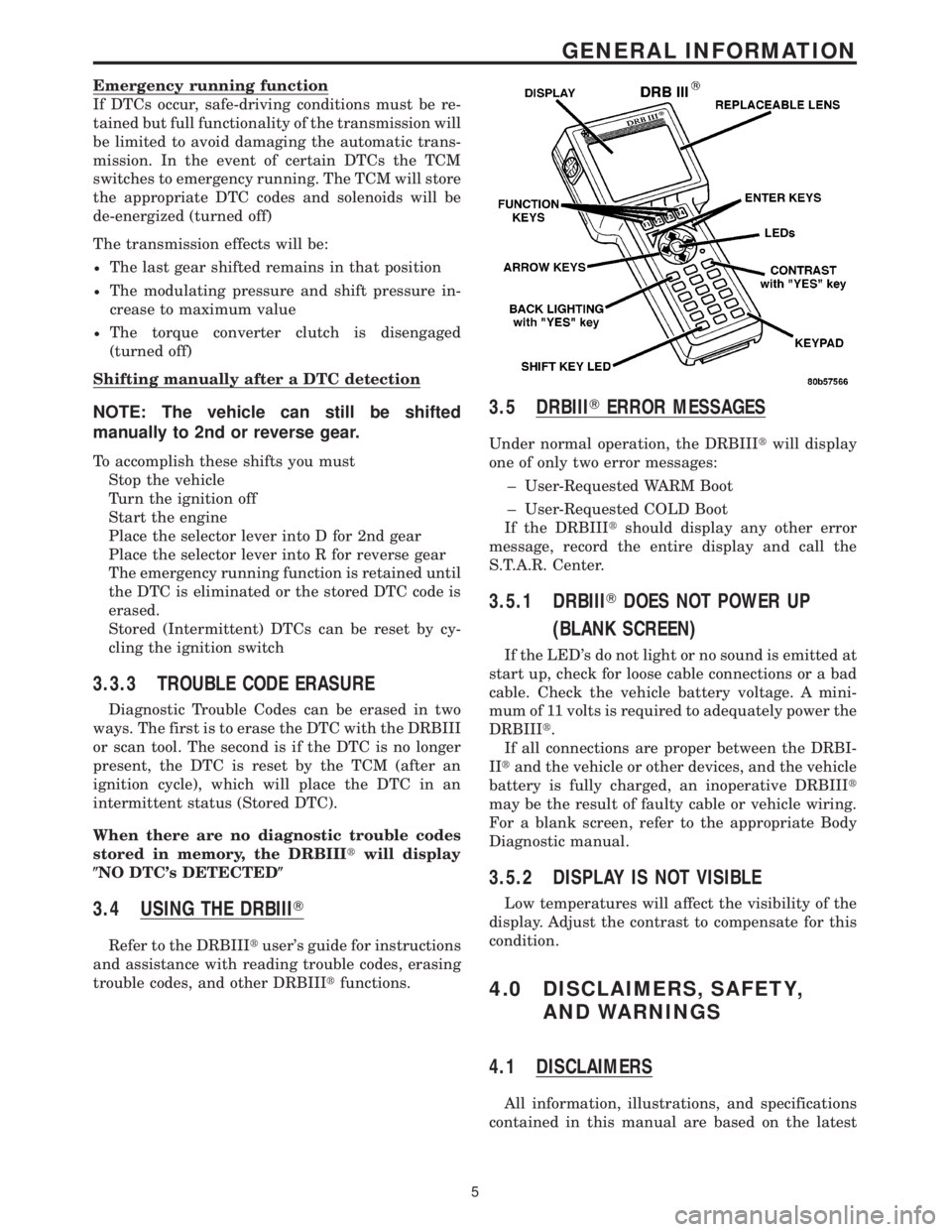
3.4 USING THE DRBIIIT
Refer to the DRBIIItuser's guide for instructions
and assistance with reading trouble codes, erasing
trouble codes, and other DRBIIItfunctions.
3.5 DRBIIITERROR MESSAGES
Under normal operation, the DRBIIItwill display
one of only two error messages:
± User-Requested WARM Boot
± User-Requested COLD Boot
If the DRBIIItshould display any other error
message, record the entire display and call the
S.T.A.R. Center.
3.5.1 DRBIIITDOES NOT POWER UP
(BLANK SCREEN)
If the LED's do not light or no sound is emitted at
start up, check for loose cable connections or a bad
cable. Check the vehicle battery voltage. A mini-
mum of 11 volts is required to adequately power the
DRBIIIt.
If all connections are proper between the DRBI-
IItand the vehicle or other devices, and the vehicle
battery is fully charged, an inoperative DRBIIIt
may be the result of faulty cable or vehicle wiring.
For a blank screen, refer to the appropriate Body
Diagnostic manual.
3.5.2 DISPLAY IS NOT VISIBLE
Low temperatures will affect the visibility of the
display. Adjust the contrast to compensate for this
condition.
4.0 DISCLAIMERS, SAFETY,
AND WARNINGS
4.1 DISCLAIMERS
All information, illustrations, and specifications
contained in this manual are based on the latest
5
GENERAL INFORMATION