2006 MERCEDES-BENZ SPRINTER service indicator
[x] Cancel search: service indicatorPage 208 of 2305

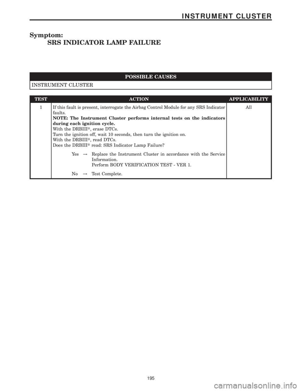
Symptom:
SRS INDICATOR LAMP FAILURE
POSSIBLE CAUSES
INSTRUMENT CLUSTER
TEST ACTION APPLICABILITY
1 If this fault is present, interrogate the Airbag Control Module for any SRS Indicator
faults.
NOTE: The Instrument Cluster performs internal tests on the indicators
during each ignition cycle.
With the DRBIIIt, erase DTCs.
Turn the ignition off, wait 10 seconds, then turn the ignition on.
With the DRBIIIt, read DTCs.
Does the DRBIIItread: SRS Indicator Lamp Failure?All
Ye s!Replace the Instrument Cluster in accordance with the Service
Information.
Perform BODY VERIFICATION TEST - VER 1.
No!Test Complete.
195
INSTRUMENT CLUSTER
Page 257 of 2305

Verification Tests
ABS VERIFICATION TEST - VER 1 APPLICABILITY
1. Turn the ignition off.
2. Connect all previously disconnected components and connectors.
3. Ensure all accessories are turned off and the battery is fully charged.
4. Ensure that the Ignition is on, and with the DRBIII, erase all Diagnostic Trouble Codes from
ALL modules. Start the engine and allow it to run for 2 minutes and fully operate the system
that was malfunctioning.
5. Turn the ignition off and wait 5 seconds. Turn the ignition on and using the DRBIII, read
DTC's from ALL modules.
6. If any Diagnostic Trouble Codes are present, return to Symptom list and troubleshoot new
or recurring symptom.
7. NOTE: If the CAB/HCU was replaced, ensure the CAB has been initialized
8. NOTE: If the SKREEM or ECM was replaced, refer to the service information for
proper programming procedures.
9. NOTE: For Sensor Circuit/Signal and Pump Motor faults, the CAB must sense all 4
wheels at 12 km/h (8 mph) before it will extinguish the ABS Indicator.
10. If there are no DTC's present after turning ignition on, road test the vehicle for at least 5
minutes. Perform several antilock braking stops.
11. CAUTION: Ensure braking capability is available before road testing.
12. Again, with the DRBIIItread DTC's. If any DTC's are present, return to Symptom list.
13. If there are no Diagnostic Trouble Codes (DTC's) present, and the customer's concern can
no longer be duplicated, the repair is complete.
Are any DTC's present or is the original concern still present?All
Ye s!Repair is not complete, refer to appropriate symptom.
No!Repair is complete.
AIRBAG VERIFICATION TEST - VER 1 APPLICABILITY
1. Remove any special tools or jumper wires and reconnect all previously disconnected
components - except the Battery.
2. WARNING: TO AVOID PERSONAL INJURY OR DEATH, TURN THE IGNITION ON,
THEN RECONNECT THE BATTERY.
3. Connect the DRBIIItto the Data Link Connector - use the most current software available.
4. Use the DRBIIItand erase the stored codes in all airbag system modules.
5. Turn the ignition off, and wait 15 seconds, then turn the ignition on.
6. Wait one minute, and read active codes and if there are none present read the stored codes.
7. Note: If equipped with Airbag On - Off switch, read the DTC's in all switch positions.
8. Note: Read the DTC's in all airbag system related modules.
9. If the DRBIIItshows any active or stored codes, return to the Symptom list and follow path
specified for that trouble code. If no active or stored codes are present, the repair is complete.
Are any DTC's present or is the original condition still present?All
YES
Repair is not complete, refer to appropriate symptom list.
NO
Repair is complete.
244
VERIFICATION TESTS
Page 325 of 2305

read opposite switch states.Note: The BS and
BLS are in the same switch housing.
BRAKE LAMP SWITCH (BLS):This switch pre-
pares the CAB for a possible antilock event. The
CAB uses an output state voltage from the BLS
when the brake pedal is either depressed/released.
The Fused Ignition Switch Output circuit supplies
12 volts to the BLS. A depressed brake pedal will
close the BLS circuit and the BLS Output circuit
supplies 12 volts at the CAB. When the driver
releases the brake pedal, the BLS Output circuit
voltage drops to 0 volts and the CAB senses the
brake pedal state. This tells the CAB what position
the brake pedal is currently in to make an ABS
event possible. When using the DRBIIItin Inputs/
Outputs, the BS and BLS will read opposite switch
states.Note: The BS and BLS are in the same
switch housing.
TRACTION CONTROL SYSTEM SWITCH
(TCSS):This switch signals the CAB to either turn
ON or OFF the TCS. The driver can toggle the
TCSS, which receives 12 volts from the D (+) Relay
Output circuit. Depending on the position of the
TCSS, open or closed, the CAB receives the TCSS
state voltage on the TCS Switch Sense circuit.
When 12 volts are applied to the TCS Switch Sense
circuit, the TCS is OFF. When no voltage is present,
the TCS is ON.
WHEEL SPEED SENSORS AND TONE
WHEELS:The Bosch 5.7 system uses one passive
WSS on each wheel. The sensor measures the wheel
speed by monitoring a rotating tone wheel. As the
teeth of the tone wheel move through the magnetic
field of the sensor an AC voltage and amperage is
generated. This signal frequency increases or de-
creases proportionally to the speed of the wheel.
The CAB monitors this signal to check for a sudden
change in single or multiple wheel decelerations. If
the deceleration of one or more wheels is not within
a predetermined amount, the CAB takes control for
antilock action through the HCU. Each WSS has a
magnetic inductive pick up coil (WSS) that is
mounted to a fixed component. There is an air gap
between the tone wheel and the speed sensor as-
sembly. Diagnostically, the coils of the Wheel Speed
Sensors have the same amount of resistance. When
measured across the CAB harness connector termi-
nals, the resistance should be between 1100 - 1800
ohms. Refer to service manual for WSS replacement
and air gap specifications.
Correct ABS operation is dependent on Tone
Wheel speed signal from the WSS. The vehicle
wheels and tires should all be the same size and
type to get accurate signals. In addition, all tires
should be at recommended tire pressures.3.7.5 SELF TESTS
The system software includes several self tests
that are performed every time the ignition is turned
on and the vehicle is driven. Some of the self tests
occur immediately, while others occur under normal
driving conditions while not in antilock operation.
The CAB checks continuously for a missing or
erratic WSS signals/circuits, tone wheels, solenoids,
pump motor or solenoid relay by performing several
tests such as: dynamic, static, ohmic, voltage drop,
and timed response. If any component exhibits a
fault during testing, the CAB will request to illumi-
nate the ABS and TCS warning indicators.
As an additional check of the ESP system, a road
test procedure is available on the DRBIIIt. This
test should be carried out when any ESP component
is replaced in order to ensure proper function. Since
the wheel speed sensors are required inputs to the
ESP, this test should also be performed if the wheel
speed sensors are replaced.
First, the brakes are applied with the vehicle
stationary. Then, the vehicle is driven at approxi-
mately 6 MPH. The driver has to make left and
right turns, with a minimum 90 degree steering
turning angle. If the indicator lamp goes out, every-
thing is in order. If the lamp remains illuminated,
the DRBIIItwill display the fault codes that are
causing the test to fail. The road test function is set
in the ESP control module, and can only be deacti-
vated once there are no more fault codes detected.
The Steering Angle Sensor must be initialized. A
procedure is carried out using the DRBIIItto
ensure that the module detects the exact position of
the sensor. The sensor must be calibrated any time
wheel alignment is changed, the steering column is
removed and re-installed, or the sensor is replaced.
3.8 USING THE DRBIIIT
Refer to the DRBIIItuser 's guide for instructions
and assistance with reading diagnostic trouble
codes, erasing diagnostic trouble codes and other
DRBIIItfunctions.
3.9 DRBIIITERROR MESSAGES
Under normal operation, the DRBIIItwill dis-
play one of only two error messages:
Ð User-Requested WARM Boot or User-Requested
COLD Boot.
If the DRBIIItshould display any other error
message, record the entire display and call the
STAR Center for information and assistance. This
is a sample of such an error message display:
4
GENERAL INFORMATION
Page 328 of 2305

display does not match the state of the pedal,
perform the proper test. For a problem with the
ªABSº warning indicator, refer to the proper test.
6. If no other problems are found, it will be neces-
sary to road test the vehicle.THE DRBIIIt
MUST NOT BE CONNECTED TO THE
DATA LINK CONNECTOR WHEN ROAD
TESTING FOR PROPER ANTILOCK OP-
ERATION. THE SYSTEM IS DISABLED
WHILE IN DIAGNOSTIC MODE.Perform
several antilock stops from above 50 Km/h (30
mph) and then repeat steps 2, 3, and 4. If any
diagnostic trouble codes are present, proceed to
the appropriate test.
7. The following conditions should be considered
``NORMAL'' operation, and no repairs should be
attempted to correct them.
± Brake pedal feedback during an ABS stop
(clicking, vibrating)
± Clicking, groaning or buzzing at 12 Km/h (8
mph) (drive off self test)
± Groaning noise during an ABS stop
± Slight brake pedal drop and pop noise when
ignition is initially turned on
± Brake pedal ratcheting down at the end of an
ABS stop
8. If the complaint is ABS ``cycling'' at the end of a
stop at low speeds, it may be caused by a
marginal wheel speed sensor signal. The sensor
air gap, tone wheel condition, and/or brakes
hanging up are possible causes of this condition.
9. After a road test in which no problems were
found, refer to any Technical Service Bulletins
that may apply.
5.0 REQUIRED TOOLS AND
EQUIPMENT
DRBIIIt(diagnostic read-out box)
jumper wires
ohmmeter
voltmeter
test light
oscilloscope
6.0 GLOSSARY OF TERMS
ABSantilock brake system
ACalternating current
BCMbody control module
BSbrake switch
BLSbrake lamp switch
CABcontroller antilock brakeDCdirect current
DLCdata link connector
DRBIIItdiagnostic read-out box
DTCdiagnostic test code
EBDelectronic brake distribution
ECMelectronic control module
HCUhydraulic control unit
HZHertz
ICinstrument cluster
LFleft front
LRleft rear
PMpump motor
RFright front
RRright rear
SOLsolenoid
TCStraction control system
TCSStraction control system switch
VSSvehicle speed signal
WSSwheel speed sensor
7
GENERAL INFORMATION
Page 400 of 2305

Verification Tests
ABS VERIFICATION TEST - VER 1 APPLICABILITY
1. Turn the ignition off.
2. Connect all previously disconnected components and connectors.
3. Ensure all accessories are turned off and the battery is fully charged.
4. Ensure that the Ignition is on, and with the DRBIII, erase all Diagnostic Trouble Codes from
ALL modules. Start the engine and allow it to run for 2 minutes and fully operate the system
that was malfunctioning.
5. Turn the ignition off and wait 5 seconds. Turn the ignition on and using the DRBIII, read
DTC's from ALL modules.
6. If any Diagnostic Trouble Codes are present, return to Symptom list and troubleshoot new
or recurring symptom.
7. NOTE: If the CAB/HCU was replaced, ensure the CAB has been initialized
8. NOTE: If the SKREEM or ECM was replaced, refer to the service information for
proper programming procedures.
9. NOTE: For Sensor Circuit/Signal and Pump Motor faults, the CAB must sense all 4
wheels at 12 km/h (8 mph) before it will extinguish the ABS Indicator.
10. If there are no DTC's present after turning ignition on, road test the vehicle for at least 5
minutes. Perform several antilock braking stops.
11. CAUTION: Ensure braking capability is available before road testing.
12. Again, with the DRBIIItread DTC's. If any DTC's are present, return to Symptom list.
13. If there are no Diagnostic Trouble Codes (DTC's) present, and the customer's concern can
no longer be duplicated, the repair is complete.
Are any DTC's present or is the original concern still present?All
Ye s!Repair is not complete, refer to appropriate symptom.
No!Repair is complete.
79
VERIFICATION TESTS
Page 716 of 2305

LUBRICATION & MAINTENANCE
TABLE OF CONTENTS
page page
FLUID TYPES
DESCRIPTION
PARTS AND LUBRICANT
RECOMMENDATIONS...................1
AUTOMATIC TRANSMISSION FLUID - NAG1 . 1
AXLE FLUID..........................2
BRAKE FLUID.........................2
HOAT COOLANT.......................2
ENGINE OIL - DIESEL ENGINES...........3
FUEL REQUIREMENTS - DIESEL ENGINE . . . 4
POWER STEERING FLUID...............5
OPERATION - AUTOMATIC TRANSMISSION
FLUID...............................5
FLUID CAPACITIES
SPECIFICATIONS - FLUID CAPACITIES.......5FLUID FILL/CHECK LOCATIONS
INSPECTION - FLUID FILL/CHECK
LOCATIONS..........................5
HOISTING
STANDARD PROCEDURE - HOISTING........5
JUMP STARTING
STANDARD PROCEDURE - JUMP STARTING . . 6
TOWING
STANDARD PROCEDURE - TOWING.........7
MAINTENANCE SCHEDULES
DESCRIPTION..........................8
INTERNATIONAL SYMBOLS
DESCRIPTION..........................9
FLUID TYPES
DESCRIPTION
PARTS AND LUBRICANT RECOMMENDATIONS
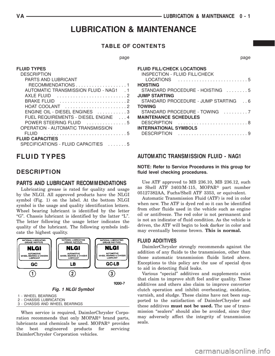
Lubricating grease is rated for quality and usage
by the NLGI. All approved products have the NLGI
symbol (Fig. 1) on the label. At the bottom NLGI
symbol is the usage and quality identification letters.
Wheel bearing lubricant is identified by the letter
ªGº. Chassis lubricant is identified by the latter ªLº.
The letter following the usage letter indicates the
quality of the lubricant. The following symbols indi-
cate the highest quality.
When service is required, DaimlerChrysler Corpo-
ration recommends that only MOPARtbrand parts,
lubricants and chemicals be used. MOPARtprovides
the best engineered products for servicing
DaimlerChrysler Corporation vehicles.
AUTOMATIC TRANSMISSION FLUID - NAG1
NOTE: Refer to Service Procedures in this group for
fluid level checking procedures.
Use ATF approved to MB 236.10, MB 236.12, such
as Shell ATF 3403/M-115, MOPARtpart number
05127382AA, Fuchs/Shell ATF 3353, or equivalent.
Automatic Transmission Fluid (ATF) is red in color
when new. The ATF is dyed red so it can be identified
from other fluids used in the vehicle such as engine
oil or antifreeze. The red color is not permanent and
is not an indicator of fluid condition. As the vehicle is
driven, the ATF will begin to look darker in color and
may eventually become brown.This is normal.
FLUID ADDITIVES
DaimlerChrysler strongly recommends against the
addition of any fluids to the transmission, other than
those automatic transmission fluids listed above.
Exceptions to this policy are the use of special dyes
to aid in detecting fluid leaks.
Various ªspecialº additives and supplements exist
that claim to improve shift feel and/or quality. These
additives and others also claim to improve converter
clutch operation and inhibit overheating, oxidation,
varnish, and sludge. These claims have not been sup-
ported to the satisfaction of DaimlerChrysler and
these additivesmust not be used.The use of trans-
mission ªsealersº should also be avoided, since they
may adversely affect the integrity of transmission
seals.
Fig. 1 NLGI Symbol
1 - WHEEL BEARINGS
2 - CHASSIS LUBRICATION
3 - CHASSIS AND WHEEL BEARINGS
VALUBRICATION & MAINTENANCE 0 - 1
Page 721 of 2305

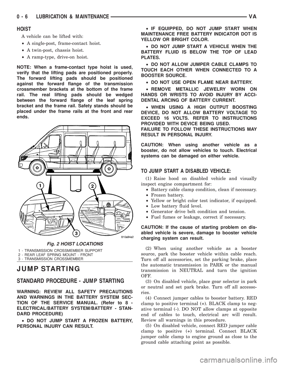
HOIST
A vehicle can be lifted with:
²A single-post, frame-contact hoist.
²A twin-post, chassis hoist.
²A ramp-type, drive-on hoist.
NOTE: When a frame-contact type hoist is used,
verify that the lifting pads are positioned properly.
The forward lifting pads should be positioned
against the forward flange of the transmission
crossmember brackets at the bottom of the frame
rail. The real lifting pads should be wedged
between the forward flange of the leaf spring
bracket and the frame rail. Safety stands should be
placed under the frame rails at the front and rear
ends.
JUMP STARTING
STANDARD PROCEDURE - JUMP STARTING
WARNING: REVIEW ALL SAFETY PRECAUTIONS
AND WARNINGS IN THE BATTERY SYSTEM SEC-
TION OF THE SERVICE MANUAL. (Refer to 8 -
ELECTRICAL/BATTERY SYSTEM/BATTERY - STAN-
DARD PROCEDURE)
²DO NOT JUMP START A FROZEN BATTERY,
PERSONAL INJURY CAN RESULT.²IF EQUIPPED, DO NOT JUMP START WHEN
MAINTENANCE FREE BATTERY INDICATOR DOT IS
YELLOW OR BRIGHT COLOR.
²DO NOT JUMP START A VEHICLE WHEN THE
BATTERY FLUID IS BELOW THE TOP OF LEAD
PLATES.
²DO NOT ALLOW JUMPER CABLE CLAMPS TO
TOUCH EACH OTHER WHEN CONNECTED TO A
BOOSTER SOURCE.
²DO NOT USE OPEN FLAME NEAR BATTERY.
²REMOVE METALLIC JEWELRY WORN ON
HANDS OR WRISTS TO AVOID INJURY BY ACCI-
DENTAL ARCING OF BATTERY CURRENT.
²WHEN USING A HIGH OUTPUT BOOSTING
DEVICE, DO NOT ALLOW BATTERY VOLTAGE TO
EXCEED 16 VOLTS. REFER TO INSTRUCTIONS
PROVIDED WITH DEVICE BEING USED.
FAILURE TO FOLLOW THESE INSTRUCTIONS MAY
RESULT IN PERSONAL INJURY.
CAUTION: When using another vehicle as a
booster, do not allow vehicles to touch. Electrical
systems can be damaged on either vehicle.
TO JUMP START A DISABLED VEHICLE:
(1) Raise hood on disabled vehicle and visually
inspect engine compartment for:
²Battery cable clamp condition, clean if necessary.
²Frozen battery.
²Yellow or bright color test indicator, if equipped.
²Low battery fluid level.
²Generator drive belt condition and tension.
²Fuel fumes or leakage, correct if necessary.
CAUTION: If the cause of starting problem on dis-
abled vehicle is severe, damage to booster vehicle
charging system can result.
(2) When using another vehicle as a booster
source, park the booster vehicle within cable reach.
Turn off all accessories, set the parking brake, place
the automatic transmission in PARK or the manual
transmission in NEUTRAL and turn the ignition
OFF.
(3) On disabled vehicle, place gear selector in park
or neutral and set park brake. Turn off all accesso-
ries.
(4) Connect jumper cables to booster battery. RED
clamp to positive terminal (+). BLACK clamp to neg-
ative terminal (-). DO NOT allow clamps at opposite
end of cables to touch, electrical arc will result.
Review all warnings in this procedure.
(5) On disabled vehicle, connect RED jumper cable
clamp to positive (+) terminal. Connect BLACK
jumper cable clamp to engine ground as close to the
ground cable attaching point as possible.
Fig. 2 HOIST LOCATIONS
1 - TRANSMISSION CROSSMEMBER SUPPORT
2 - REAR LEAF SPRING MOUNT - FRONT
3 - TRANSMISSION CROSSMEMBER
0 - 6 LUBRICATION & MAINTENANCEVA
Page 723 of 2305

effect panels. If necessary, remove the wheels from
the lifted end of the vehicle and lower the vehicle
closer to the ground, to increase the ground clearance
at the opposite end of the vehicle. Install lug nuts on
wheel attaching studs to retain brake drums.
RAMP ANGLE
If a vehicle with flat-bed towing equipment is used,
the approach ramp angle should not exceed 15
degrees.
TOWING WHEN KEYS ARE NOT AVAILABLE
When the vehicle is locked and keys are not avail-
able, use a flat bed hauler. A Wheel-lift or Sling-type
device can be used provided all the wheels are lifted
off the ground using tow dollies.
MAINTENANCE SCHEDULES
DESCRIPTION
The use of special lubricant additives is not recom-
mended. The use of such additives may affect the
warranty rights. With regard to legal stipulations
concerning emissions control, please note that
engines have to be serviced and adjusted in accor-
dance with special instructions and using special
measuring equipment. Modifications to or interfer-
ence with the emissions control systems are not per-
missible.
MAINTENANCE - WITHOUT ASSYST MAINTE-
NANCE COMPUTER
Maintenance Intervals
²Oil service ±Normal Operationevery 10,000
miles or 16,000 km or 12 months.
²Maintenance service every 30,000 miles or
48,000 km.
Additional work must be carried out at yearly
intervals.
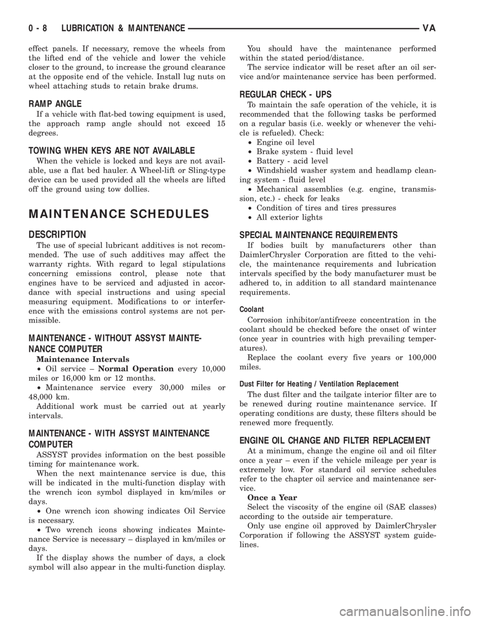
MAINTENANCE - WITH ASSYST MAINTENANCE
COMPUTER
ASSYST provides information on the best possible
timing for maintenance work.
When the next maintenance service is due, this
will be indicated in the multi-function display with
the wrench icon symbol displayed in km/miles or
days.
²One wrench icon showing indicates Oil Service
is necessary.
²Two wrench icons showing indicates Mainte-
nance Service is necessary ± displayed in km/miles or
days.
If the display shows the number of days, a clock
symbol will also appear in the multi-function display.You should have the maintenance performed
within the stated period/distance.
The service indicator will be reset after an oil ser-
vice and/or maintenance service has been performed.
REGULAR CHECK - UPS
To maintain the safe operation of the vehicle, it is
recommended that the following tasks be performed
on a regular basis (i.e. weekly or whenever the vehi-
cle is refueled). Check:
²Engine oil level
²Brake system - fluid level
²Battery - acid level
²Windshield washer system and headlamp clean-
ing system - fluid level
²Mechanical assemblies (e.g. engine, transmis-
sion, etc.) - check for leaks
²Condition of tires and tires pressures
²All exterior lights
SPECIAL MAINTENANCE REQUIREMENTS
If bodies built by manufacturers other than
DaimlerChrysler Corporation are fitted to the vehi-
cle, the maintenance requirements and lubrication
intervals specified by the body manufacturer must be
adhered to, in addition to all standard maintenance
requirements.
Coolant
Corrosion inhibitor/antifreeze concentration in the
coolant should be checked before the onset of winter
(once year in countries with high prevailing temper-
atures).
Replace the coolant every five years or 100,000
miles.
Dust Filter for Heating / Ventilation Replacement
The dust filter and the tailgate interior filter are to
be renewed during routine maintenance service. If
operating conditions are dusty, these filters should be
renewed more frequently.
ENGINE OIL CHANGE AND FILTER REPLACEMENT
At a minimum, change the engine oil and oil filter
once a year ± even if the vehicle mileage per year is
extremely low. For standard oil service schedules
refer to the chapter oil service and maintenance ser-
vice.
Once a Year
Select the viscosity of the engine oil (SAE classes)
according to the outside air temperature.
Only use engine oil approved by DaimlerChrysler
Corporation if following the ASSYST system guide-
lines.
0 - 8 LUBRICATION & MAINTENANCEVA