Page 358 of 409

357 Practical hints
Batteries
Warning!
G
Do not place metal objects on the battery as
this could result in a short circuit.
Use leak-proof batteries only to avoid the
risk of acid burns in the event of an
accident.
Warning!
G
The brake system requires electrical power
to operate.
A malfunction in the vehicle’s power supply
or electrical system may impair brake sys-
tem operation and switch it into its emer-
gency operation mode. The same applies if
battery is disconnected. To brake, the driver
must then apply significantly greater brake
pedal pressure and depress the pedal much
further to obtain the expected braking ef-
fect. If necessary, apply full pressure to the
brake pedal. Brakes are only applied to the
front wheels. Stopping distance is in-
creased! Adjust your driving style according-
ly. For more information, see
“Electrohydraulic brake system”
(�page 84).
Warning!
G
With a disconnected battery�
you will no longer be able to turn the
SmartKey in the starter switch
�
the gear selector lever will remain
locked in positionP
Page 359 of 409

358 Practical hintsBatteriesCharging the batteries
You can obtain detailed information on
charging the battery from your authorized
Mercedes-Benz Center.Charging with the battery charger
Only use the battery charge unit approved
by Mercedes-Benz and supplied with your
vehicle. This charger is designed to auto-
matically control the charge rate, and
charge the battery or maintain the existing
charge in the battery while the vehicle is
parked and not being driven for long peri-
ods of time (on average approximately
3 weeks or more). Not driving the vehicle
for such extended periods may cause the
charge in the vehicle battery to drop. Using the charging point
The charging point for the battery charger
is located next to the CD-changer on the
left-hand side in the trunk.
1Charging point
�
Remove the SmartKey from the starter
switch.
�
Open the cover of the charging
point1.
�
Connect the battery charger with the
charging point 1.
Warning!
G
Never charge a battery while still installed in
the vehicle unless the battery charge unit
approved by Mercedes-Benz (supplied with
your vehicle) is being used. Gases may es-
cape during charging and cause explosions
that may result in paint damage, corrosion
or personal injury.
A battery charge unit specially adapted for
Mercedes-Benz vehicles and tested and ap-
proved by Mercedes-Benz is available, per-
mitting the charging of the battery in its
installed position. Contact an authorized
Mercedes-Benz Center for information and
availability. Charge battery in accordance
with the separate operating instructions for
the battery charger.
Page 360 of 409
359 Practical hints
Batteries
�
Observe and follow the separate oper-
ating instructions for the battery
charger.
�
Charge up the battery.
The battery charger switches off auto-
matically when the battery is sufficient-
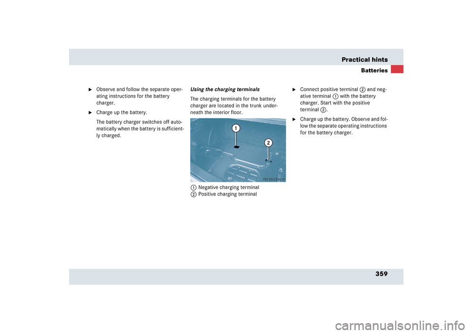
ly charged.Using the charging terminals
The charging terminals for the battery
charger are located in the trunk under-
neath the interior floor.
1Negative charging terminal
2Positive charging terminal
�
Connect positive terminal2 and neg-
ative terminal1 with the battery
charger. Start with the positive
terminal2.
�
Charge up the battery. Observe and fol-
low the separate operating instructions
for the battery charger.
Page 363 of 409
.1Towing eye bolt
�
Remove cover from the access hole.")
362 Practical hintsTowing the vehicleInstalling/reinstalling towing eye bolt�
Take the towing eye bolt1 from its
storage compartment (
�page 342).1Towing eye bolt
�
Remove cover from the access hole.
�
Screw towing eye bolt1 in to its stop.
�
Remove the towing eye bolt when you
no longer need it. To do this, carry out
the above steps in reverse order.
Points to bear in mind�
The vehicle must not be tow-started.
�
If the vehicle is to be towed, only tow it
with all wheels on the ground.
�
If the vehicle has suffered transmission
damage, only tow it with the propeller
shaft disconnected.
�
Before towing the vehicle, make sure
the battery is connected and charged.
Otherwise you will not be able to switch
on the ignition and move the selector
lever to N. There will then be no power
assistance when steering and braking.
Transporting the vehicle
The towing eye bolt can be used to pull the
vehicle onto a trailer or transporter for
transporting purposes.�
Move the selector lever to N.
iThe gear selector lever will remain
locked in positionP and the SmartKey
will not turn in the starter switch if the
battery is disconnected or discharged.
See notes on the battery (
�page 356).
!Only secure the tow bar to the towing
eye bolt. The vehicle could otherwise
be damaged.!Your vehicle is equipped with a front
towing eye bolt only (
�page 362).
You cannot tow other vehicles with
your vehicle.
!Due to the low clearance height of the
SLR, care must be taken when loading
and unloading from a transporter to
avoid damaging the vehicle body work.
To secure the vehicle, only tie it down
by the wheels or tires. Otherwise it
could be damaged.
Page 375 of 409
374 Technical dataElectrical systemGenerator (alternator)
14 V/150 A
Starter motor
12 V/1.7 kW
BatteryStarter battery
12 V/35 Ah
Battery for electrical consumers
12 V/70 Ah
Spark plugs
NGK ILFR6A
Electrode gap
0.031 in (0.8 mm)
Tightening torque
18 – 22 lb-ft (25 – 30 Nm)
Page 390 of 409

SRS
(Supplemental R
estraint S
ystem)
Seat belts, emergency tensioning de-
vice and airbags. Though independent
systems, they are closely interfaced to
pro")
389 Technical terms
Sidewall
(
�page 283)
SRS
(Supplemental R
estraint S
ystem)
Seat belts, emergency tensioning de-
vice and airbags. Though independent
systems, they are closely interfaced to
provide effective occupant protection.
Tele Aid
(Tele
matic A
larm I
dentification on D
e--
mand)
The Tele Aid system consists of three
types of response: automatic and man-
ual emergency, roadside assistance
and information. Tele Aid is initially ac-
tivated by completing a subscriber
agreement and placing an acquain-
tance call.
The Tele Aid system is operational pro-
vided that the vehicle’s battery is
charged, properly connected, not dam-
aged and cellular and GPS coverage is
available.Tightening torque
Force times lever arm (e.g. a lug
wrench) with which threaded fasteners
such as wheel bolts are tightened.
TIN
(T
ire I
dentification N
umber)
(
�page 283)
Tire load rating
(�page 283)
Tire ply composition and material used
(�page 283)
Tire speed rating
(�page 283)
TIREFIT kit
Accessory for emergency and tempo-
rary tire repair. The TIREFIT kit consists
of a container with sealant material, a
filler hose and an air compressor.
Traction
(�page 283)Tread
(
�page 283)
Treadwear indicators
(�page 283)
Uniform Tire Quality Grading Standards
(�page 284)
Vehicle capacity weight
(�page 284)
Vehicle maximum load on the tire
(�page 284)
VIN
(Vehicle I
dentification N
umber)
The number set by the manufacturer
and placed on the body to uniquely
identify each vehicle produced.
Page 393 of 409

392 IndexAutomatic climate control 182
Adjusting air volume 186
Air conditioning refrigerant 378
Air conditioning, Cooling 192
Air distribution 187
Air recirculation mode 188
Air vents 183
Control panel 184
Deactivating system 191
Defrosting 181, 188
MAXCOOL 187
Residual heat utilization 190
Side air vents 31
Temperature 185
Temperature sensor 33
Automatic headlamp mode 106
Automatic lighting control, Interior
lighting 111Automatic transmission 167
Accelerator position 173
Damage 362
Driving tips 173
Emergency operation (Limp Home
Mode) 178
Gear ranges 170
Gear selector lever 32, 167
Gear selector lever position 167, 171
Gear shifting malfunctions 178
Kickdown 173
Manual gearshift program 176
Manual shifting 168
One-touch gearshifting 168
Shift program mode selector
switch 173
Starting the engine 49
Steering wheel gearshift control 174
Towing 362
Transmission fluid level 249
Automatic transmission fluid 249B
BabySmart
TM
Airbag deactivation system 75, 385
Compatible child seats 385
Self-test 75
Backup lamp 349
Messages in the multifunction
display 332
Bar 281
BAS 81, 385
Batteries, SmartKey
Checking battery condition 99
Replacing 346
Batteries, Vehicle 251
Charging 358
Consumer battery 356
Jump starting 356
Maintenance 356
Messages in the multifunction
display 315
Starter battery 251
Batteries, vehicle
Consumer battery 251
Battery charger 358
Bead 281
Bi-Xenon headlamps 385
Page 399 of 409

398 IndexInstrument cluster 28, 113, 387
Illumination brightness 113
Lamps 298
Messages in display see Multifunction
display messages
Multifunction display 117
Instrument lighting 113
Instrument panel see Instrument cluster
Instruments and controls see Cockpit
Interior lighting 111
Delayed switch-off 135
Interior rear view mirror 44
Auto-dimming 179
Interior storage spaces see Storage com-
partments
J
Jacking up the vehicle 351
Jump starting 356K
Key, Mechanical 344
Key, SmartKey
Battery check lamp 98
Checking the batteries 99
Factory setting 98
Locking/unlocking 96
Locking/unlocking, Global setting 98
Locking/unlocking, Selective
setting 98
Loss of 99
Messages in the multifunction
display 329
Opening and closing the
windows 195, 196
Positions in starter switch 40
Remote control 96
Replacing the batteries 346
Turning off the engine 58
Unlocking, Trunk 99
Kickdown 173, 387
Kilopascal 282
Knee airbags 68L
Labels
Certification 368
Emission control label 368
Vacuum line routing 368
Lamps
Exterior 348
Lamps, exterior
Messages in the multifunction
display 330
Lamps, indicator and warning
ABS 29, 299
ABS/ESP
®
29, 298
Airbrake 29, 303
Battery, SmartKey 98
Brake 29, 300
Center console 306
Coolant 29, 302
Engine malfunction 29, 301
Engine oil temperature 29, 303
Fog lamps 108
Fuel reserve 29, 303
Gearshift 29, 303
High beam 29
Instrument cluster 298
Maintenance service indicator 289

14 V/150 A
Starter motor
12 V/1.7 kW
BatteryStarter battery
12 V/35 Ah
Battery for electrical consumers
12 V/70 Ah
Spark plugs
NGK ILFR6A
Elec")