Page 380 of 480

379 Practical hints
What to do if …
Left display
Right display
Possible cause/consequence
Possible solution
.
Turn signal
Rear right
Substitute
bulb on
The right rear turn signal lamp is
malfunctioning. A substitute bulb
has been brought into use.
�
Replace the bulb as soon as possible.
Visit workshop!
The display for the lights is malfunc-
tioning.
�
Visit an authorized Mercedes-Benz Center as
soon as possible.
C
Raise
roll-over bar
The roll bar is malfunctioning.
�
Raise the roll bar using the roll bar button
(�page 75).
�
Have the roll bar checked by an authorized
Mercedes-Benz Center.
<
Seat belt system
Drive to
workshop
The seat belt system is malfunction-
ing.
�
Visit an authorized Mercedes-Benz Center as
soon as possible.
L
TeleAid
Drive to
workshop
One or more main functions of the
Tele Aid system are malfunctioning.
�
Have the Tele Aid system checked by an au-
thorized Mercedes-Benz Center.
t
Function
unavailable
This display appears if button t
or s on the multifunction steer-
ing wheel is pressed and the vehicle
is not equipped with a telephone.
Page 391 of 480
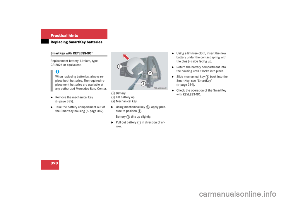
390 Practical hintsReplacing SmartKey batteriesSmartKey with KEYLESS-GO*
Replacement battery: Lithium, type
CR 2025 or equivalent.�
Remove the mechanical key
(�page 385).
�
Take the battery compartment out of
the SmartKey housing (
�page 389).1Battery
2Tilt battery up
3Mechanical key
�
Using mechanical key3, apply pres-
sure to position 2.
Battery 1 tilts up slightly.
�
Pull out battery 1 in direction of ar-
row.
�
Using a lint-free cloth, insert the new
battery under the contact spring with
the plus (+) side facing up.
�
Return the battery compartment into
the housing until it locks into place.
�
Slide mechanical key 1 back into the
SmartKey, see “SmartKey”
(�page 389).
�
Check the operation of the SmartKey
with KEYLESS-GO.
iWhen replacing batteries, always re-
place both batteries. The required re-
placement batteries are available at
any authorized Mercedes-Benz Center.
Page 392 of 480
391 Practical hints
Replacing bulbs
�Replacing bulbs
Bulbs
Safe vehicle operation depends on proper
exterior lighting and signaling. It is there-
fore essential that all bulbs and lamp as-
semblies are in good working order at all
times.
Correct headlamp adjustment is extremely
important. Have headlamps checked and
readjusted at regular intervals and when a
bulb has been replaced. See an authorized
Mercedes-Benz Center for headlamp ad-
justment.
iIf the headlamps or front fog lamps are
fogged up on the inside as a result of
high humidity, driving the vehicle a dis-
tance with the lights on should clear up
the fogging.
iSubstitute bulbs will be brought into
use when the following lamps malfunc-
tion:�
Turn signal lamps
�
Brake lamps
�
Parking lamps
�
Tail lamps
Observe the messages in the multi-
function display (
�page 345).
Page 394 of 480

393 Practical hints
Replacing bulbs
Notes on bulb replacement�
Only use 12-volt bulbs of the same type
and with the specified watt rating.
�
Switch the lights off before changing a
bulb to prevent short circuits.
�
Always use a clean lint-free cloth when
handling bulbs.
�
Your hands should be dry and free of oil
and grease.
�
If the newly installed bulb does not
come on, visit an authorized
Mercedes-Benz Center.Have the LEDs and bulbs for the following
lamps replaced by an authorized
Mercedes-Benz Center:
�
the additional turn signals in the exteri-
or rear view mirrors
�
the high mounted brake lamp
�
the brake lamps
�
the parking lamps and the side marker
lamps in the tail lamp unit
�
the rear fog lamps
�
the low beam (Xenon or Bi-Xenon*)
lamps
�
the front fog lamps
�
the front side marker lamps
Warning!
G
Bulbs and bulb sockets can be very hot. Al-
low the lamp to cool down before changing
a bulb.
Keep bulbs out of reach of children.
Halogen lamps contain pressurized gas. A
bulb can explode if you:�
touch or move it when hot
�
drop the bulb
�
scratch the bulb
Wear eye and hand protection.
Because of high voltage in Xenon lamps, it is
dangerous to replace the bulb or repair the
lamp and its components. We recommend
that you have such work done by a qualified
technician.
iHave the headlamp adjustment
checked regularly.
Page 402 of 480

401 Practical hints
Flat tire
�
Screw the air pump’s air hose5 onto
flange6 of the TIREFIT container.
�
Stick TIREFIT container1 upside
down into notch3 of the electric air
pump.
7Tire valve
8Electric air pump switch
9Air hose with pressure gauge and vent
screw
aFiller hose
�
Unscrew the valve cap from tire
valve7.
�
Screw filler hosea onto tire valve7.
�
Insert electrical plug4 into vehicle
cigarette lighter socket.
�
Turn the SmartKey in the starter switch
to position1 (
�page 36).
or
�
Press the KEYLESS-GO* start/stop
button (
�page 37) on the gear selec-
tor lever once. Do not depress brake
pedal.
�
PressI on electric air pump switch8.
The electric air pump should now
switch on and inflate the tire.After 5 minutes, the pressure gauge must
display at least 26 psi (1.8 bar). The air
hose can become hot during inflation.
Please exercise appropriate caution.
�
If this tire inflation pressure is not at-
tained, turn off the electric air pump,
detach the filler hose from the tire
valve, and drive vehicle back and forth
very slowly approximately 30 ft (10 m).
This serves to better distribute the
TIREFIT sealant material inside the tire.
�
Unscrew the air pump’s air hose5
from flange6 of the TIREFIT contain-
er.
�
Screw air hose5onto tire valve7.
�
Inflate the tire again.
Warning!
G
Observe safety instructions on air pump la-
bel.
!Do not operate the electric air pump
longer than 8 minutes without interrup-
tion. Otherwise it may overheat.
You may operate the air pump again af-
ter it has cooled off.
��
Page 408 of 480
.
�
Continue to turn the crank")
407 Practical hints
Flat tire
�
Keeping jack in this position, turn
crank3 clockwise until the jack base
meets the ground. Make sure the jack
is vertical (plumb line).
�
Continue to turn the crank until the tire
is a maximum of 1.2 in (3 cm) from the
ground.Removing the wheel
1Alignment bolt
�
Unscrew upper-most wheel bolt and re-
move.
�
Replace this wheel bolt with alignment
bolt1 supplied in the tool kit.
�
Remove the remaining bolts.
�
Remove the wheel.Mounting the new wheel
�
Clean contact surfaces of wheel and
wheel hub.
�
Guide the spare wheel onto the align-
ment bolt and push it on.
�
Insert wheel bolts and tighten them
slightly.
!Do not place wheel bolts in sand or dirt.
This could result in damage to the bolt
and wheel hub threads.
Warning!
G
Inflate spare wheel tire only after the wheel
is properly mounted.
Inflate the spare wheel tire using the electric
pump (
�page 408) before
lowering the ve-
hicle.
Warning!
G
Always replace wheel bolts that are dam-
aged or rusted.
Never apply oil or grease to wheel bolts.
��
Page 409 of 480
.
1Flap
2Air")
408 Practical hintsFlat tire�
Unscrew the alignment bolt, install last
wheel bolt and tighten slightly.Inflating the spare tire
�
Take the electric air pump out of the
trunk (
�page 383).
1Flap
2Air pump switch
3Electrical plug
4Air hose with pressure gauge and vent
screw
5Union nut
�
Open flap 1 on air pump.
�
Pull out electrical plug 3 and air hose
with the pressure gauge 4.
�
Remove the valve cap from the tire
valve.
�
Screw union nut 5 onto the tire valve.
�
Insert electrical plug 3 into vehicle ci-
gar lighter socket.
Damaged wheel hub threads should be re-
paired immediately. Do not continue to drive
under these circumstances! Contact an au-
thorized Mercedes-Benz Center or call
Roadside Assistance.
Incorrect wheel bolts or improperly tight-
ened wheel bolts can cause the wheel to
come off. This could cause an accident. Be
sure to use the correct wheel bolts.Warning!
G
Only use genuine equipment
Mercedes-Benz wheel bolts. They are identi-
fied by the Mercedes star. Other wheel bolts
may come loose.
Do not tighten the wheel bolts when the ve-
hicle is raised. Otherwise the vehicle could
fall off the jack.
!Do not lower the vehicle before inflat-
ing the spare wheel tire. Otherwise the
rim may be damaged.Warning!
G
Observe instructions on air pump label.
��
Page 421 of 480

420 Practical hintsJump startingThe starter battery is located on the right
side of the engine compartment.�
Make sure the two vehicles do not
touch.
�
Turn off all electrical consumers.
�
Apply the parking brake (
�page 59).
�
Shift gear selector lever to positionP.
�
Open the hood (
�page 272).
�
Remove the red cover from positive ter-
minal on both vehicles (
�page 413).1Negative terminal of charged battery
2Negative terminal of discharged
battery
3Positive terminal of discharged battery
4Positive terminal of charged battery
�
Connect positive terminals 3 and 4
of the batteries with the jumper cables.
Clamp cable to charged battery 4
first.
�
Start the engine of the vehicle with the
charged battery and run at idle speed.
�
Connect negative terminals 1 and 2
of the batteries with the jumper cables.
Clamp cable to charged battery 1
first.
�
Start the engine of the disabled vehi-
cle.
You can now turn on the electrical con-
sumers. Do not turn on the lights under
any circumstances.
�
Remove the jumper cables first from
negative terminals 2 and 1 and then
from positive terminals 3 and 4.
You can now turn on the lights.
�
Have the battery checked at the near-
est Mercedes-Benz Center.
Warning!
G
Keep flames or sparks away from battery.
Do not smoke.
Observe all safety instructions and precau-
tions when handling automotive batteries
(�page 279).
!Never invert the terminal connections.
!Do not tow-start the vehicle.