Page 442 of 561

441 Practical hints
What to do if …
Display symbol
Display messages
Possible cause/consequence
Possible solution
F
Key
still in vehicle
A SmartKey with KEYLESS-GO*
left in the vehicle was recog-
nized while trying to lock the ve-
hicle from the outside.
�
Take the SmartKey with KEYLESS-GO*
out of the vehicle.
Remove key
You have forgotten to remove
the SmartKey.
�
Remove the SmartKey from the starter
switch.
Replace key
Drive to workshop
There is no additional code avail-
able for SmartKey or SmartKey
with KEYLESS-GO*.
�
Visit an authorized Mercedes-Benz Light
Truck Center as soon as possible.
Key
Check battery
The batteries in the SmartKey
with KEYLESS-GO* are dis-
charged.
�
Replace the batteries (
�page 464).
Do not
forget key
This message appears for a
maximum of 60 seconds if the
driver’s door is opened with the
engine shut off and no SmartKey
in the starter switch.
This message is only a reminder.
�
Insert SmartKey in the starter switch.
or
�
Take the SmartKey with KEYLESS-GO*
with you when leaving the vehicle.
Page 460 of 561
459 Practical hints
Unlocking / locking in an emergency
�Unlocking / locking in an emergency
Unlocking the vehicle
If you cannot unlock the vehicle with the
SmartKey or KEYLESS-GO*, open the driv-
er’s door using the mechanical key.
Removing the mechanical key
SmartKey1Mechanical key locking tab
2Mechanical key
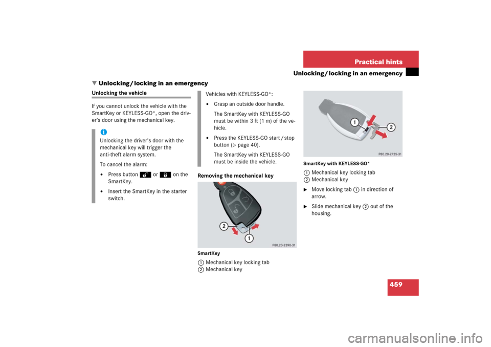
SmartKey with KEYLESS-GO*1Mechanical key locking tab
2Mechanical key�
Move locking tab1 in direction of
arrow.
�
Slide mechanical key2 out of the
housing.
iUnlocking the driver’s door with the
mechanical key will trigger the
anti-theft alarm system.
To cancel the alarm:�
Press buttonŒ or‹on the
SmartKey.
�
Insert the SmartKey in the starter
switch.
Vehicles with KEYLESS-GO*:�
Grasp an outside door handle.
The SmartKey with KEYLESS-GO
must be within 3 ft (1 m) of the ve-
hicle.
�
Press the KEYLESS-GO start / stop
button (
�page 40).
The SmartKey with KEYLESS-GO
must be inside the vehicle.
Page 461 of 561

460 Practical hintsUnlocking / locking in an emergencyUnlocking the driver’s door
1Unlocking
2Mechanical key�
Insert mechanical key 2 into the
driver’s door lock until it stops.
�
Turn mechanical key 2 counterclock-
wise to position1 and hold it there.
�
Pull the door handle until the locking
knob moves up.
The driver’s door is unlocked.
�
Pull the door handle once more to open
the driver’s door.
Locking the vehicle
If you cannot lock the vehicle with the
SmartKey or KEYLESS-GO*, lock the vehi-
cle carrying out the following steps.�
Close the front passenger door, the
rear right door and the tailgate.
�
Open the driver’s door and the rear left
door.
�
Press the central locking switch on the
driver’s door (
�page 131).
The locking knobs of the front passen-
ger door and the rear doors move
down.
If the vehicle battery is disconnected or
drained:
�
Press down the locking knobs of
the front passenger door and the
rear doors manually.
�
Exit the vehicle.
�
Close the driver’s door.
�
Enter the vehicle through the rear left
door.
�
Press down the locking knob of the
driver’s door.
�
Exit the vehicle.
�
Close the rear left door.
The vehicle is locked.!To prevent inadvertent lockout, make
sure to have the SmartKey or SmartKey
with KEYLESS-GO* with you before
proceeding with the next step. The next
step will lock the vehicle.
Page 463 of 561

462 Practical hintsOpening / closing in an emergencyPower tilt/sliding sunroof*
You can open or close the tilt/sliding
sunroof manually should an electrical
malfunction occur.
The tilt/sliding sunroof drive is located
behind a cover on the overhead control
panel.
1Cover�
Remove the SmartKey from the starter
switch.Vehicles with KEYLESS-GO*:
�
Turn off the engine by pressing the
KEYLESS-GO start/stop button
(�page 66).
�
Open the driver’s door (this puts
the starter switch to position0,
same as with the SmartKey re-
moved from starter switch). The
driver’s door can then be closed
again.
�
Press on cover1 at the position indi-
cated by the arrow.
�
Take off cover 1.
2Crank
�
Take crank 2 out of the Operator’s
Manual pouch.
�
Insert crank2 into hole.
�
Turn crank2 clockwise to�
slide sunroof closed
�
raise sunroof at the rear
�
Turn crank2 counterclockwise to�
slide sunroof open
�
lower sunroof at the rear
iTurn crank2 slowly and smoothly.
The tilt/sliding sunroof must be syn-
chronized if it has been operated man-
ually (
�page 258).
iThe panorama roof with power
tilt/sliding panel* cannot be operated
as described. Contact an authorized
Mercedes-Benz Light Truck Center.
Page 495 of 561
.
�
Carry out steps 6 to 1 in reverse order
to complete reinstall the battery,
(�page 492) to (
�page 490).
Step 1")
494 Practical hintsBattery�
Carry out step 8 to reconnect the bat-
tery (
�page 493).
�
Carry out steps 6 to 1 in reverse order
to complete reinstall the battery,
(�page 492) to (
�page 490).
Step 11 (Reconnecting)
�
If the battery has been removed, carry
out step 9 (
�page 493) first and then
step 7 (
�page 493), both in reverse
order, before starting the connecting
procedure.
�
Open the driver’s door.
�
Make sure the SmartKey is removed
from the starter switch.
Vehicles with KEYLESS-GO*:�
Make sure the vehicle’s on-board
electronics have status 0.
With the driver’s door opened, the
vehicle’s on-board electronics have
status 0, same as SmartKey re-
moved from the starter switch
(�page 39).
�
Connect the positive lead to the posi-
tive terminal and fasten it’s cover
(�page 493).
�
Connect the negative lead to the nega-
tive terminal (
�page 493).
!Never invert the terminal connections!
iThe following procedures must be car-
ried out following any interruption of
battery power (e.g. due to disconnec-
tion):�
Set the clock (
�page 180).
Vehicles with Modular COMAND
system with navigation module*:
Time and date are set automatical-
ly.
�
Synchronize the door windows
(�page 251).
�
Synchronize the power tilt/sliding
sunroof* (
�page 258).
�
Synchronize the power tilt/sliding
panel* (
�page 262).
�
Synchronize the power folding
exterior rear view mirrors*
(�page 211).
��
Page 502 of 561

501 Practical hints
Towing the vehicle
Installing towing eye bolts
The front towing eye is located behind a
cover on the passenger side below the
front bumper.
1Towing eye cover
iThe vehicle cannot be started via
tow-start.iIf the battery is disconnected or dis-
charged, the automatic transmission
will remain locked in positionP and the
SmartKey will not turn in the starter
switch. For more information, see “Bat-
tery” (
�page 487) and “Jump starting”
(
�page 496).
!When towing the vehicle with all wheels
on the ground, note the following:
With the automatic central locking
activated and the ignition in position2
(�page 38), the vehicle doors lock if
the left front wheel is turning at a speed
of approx. 9 mph (15 km / h) or above.
To prevent the vehicle doors from
locking, deactivate the automatic
central locking (
�page 130).
Switch off the tow-away alarm
(
�page 107).
Towing of the vehicle should only be
done using the towing eye. Never
attach tow cable, tow rope or tow rod
to vehicle chassis, frame or suspension
parts.
Page 530 of 561

Prevents the wheels from locking up
during braking so that the vehicle can
continue to be steered.
Accessory weight
(
�page 385)
ADS
(Adaptive D
am")
529 Technical terms
ABS
(A
ntilock B
rake S
ystem)
Prevents the wheels from locking up
during braking so that the vehicle can
continue to be steered.
Accessory weight
(
�page 385)
ADS
(Adaptive D
amping S
ystem)
Automatically adapts the optimum sus-
pension damping to prevailing driving
conditions.
Airmatic*
Automatically selects the optimum sus-
pension tuning and ride height for your
vehicle. Airmatic consists of two com-
ponents:
�
Adaptive Damping System
�
Vehicle level control
Air pressure
(
�page 385)Alignment bolt
Metal pin with thread. The centering
pin is an aid used when changing a tire
to align the wheel with the wheel hub.
Aspect ratio
(
�page 385)
Bar
(�page 386)
BAS
(Brake A
ssist S
ystem)
System for potentially reducing braking
distances in emergency braking situa-
tions. The system is activated when it
senses an emergency based on how
fast the brake is applied.
Bead
(
�page 386)
Bi-Xenon headlamps*
Headlamps which use an electric arc as
the light source and produce a more
intense light than filament headlamps.
Bi-Xenon headlamps produce low
beam and high beam.CAC
(C
ustomer A
ssistance C
enter)
Mercedes-Benz customer service
center, which can help you with any
questions about your vehicle and
provide assistance in the event of a
breakdown.
CAN system
(C
ontroller A
rea N
etwork)
Data bus network serving to control
vehicle functions such as door locking
or windshield wiping.
Cockpit
All instruments, switches, buttons and
indicator / warning lamps in the
passenger compartment needed for
vehicle operation and monitoring.
Cold tire inflation pressure
(
�page 386)
Page 532 of 561

Satellite-based system for relaying
geographic location information to and
from vehicles equipped with special re-
ceivers. Employs CD or DVD d")
531 Technical terms
GPS
(G
lobal P
ositioning S
ystem)
Satellite-based system for relaying
geographic location information to and
from vehicles equipped with special re-
ceivers. Employs CD or DVD digital
maps for navigation.
GVW
(G
ross V
ehicle W
eight)
(
�page 386)
GVWR
(Gross V
ehicle W
eight R
ating)
(
�page 386)
Instrument cluster
The displays and indicator/warning
lamps in the driver’s field of vision, in-
cluding the tachometer, speedometer,
engine temperature and fuel gauge.Kickdown
Depressing the accelerator past the
point of resistance shifts the transmis-
sion down to the lowest possible gear.
This very quickly accelerates the vehi-
cle and should not be used for normal
acceleration needs.
Kilopascal (kPa)
(
�page 386)
Line of fall
The direct line that an object moves
downhill when influenced by the force
of gravity alone.
Locking knob
Knob on the door which indicates
whether the door is locked or un-
locked. Pushing the locking knob down
on an individual door from inside will
lock that door.Maintenance System (U.S. vehicles)
Maintenance service indicator in the
multifunction display that informs the
driver when the next vehicle mainte-
nance service is due. The Maintenance
system tracks distance driven and the
time elapsed since the last mainte-
nance service, calculates other mainte-
nance service work required, and calls
for the next service accordingly.
Maximum load rating
(
�page 387)
Maximum loaded vehicle weight
(�page 387)
Maximum tire inflation pressure
(�page 387)
Modular COMAND System
Information and operating center for
vehicle sound and communications
systems, including the radio and the ra-
dio and navigation system, as well as
for other optional equipment (CD
changer, telephone, etc.).