Page 491 of 561

�
Set the automatic position to P
(�page 199).
�
Firmly depress the parking brake
(�page 65).
�
Turn off the engine (
�page 66).
�
Leave the ignition")
490 Practical hintsBatteryStep 1 (Disconnecting)
�
Set the automatic position to P
(�page 199).
�
Firmly depress the parking brake
(�page 65).
�
Turn off the engine (
�page 66).
�
Leave the ignition switched on
(�page 38).
�
Switch off all electrical consumers.
�
Read and observe safety instructions
and precautions (
�page 487).
�
Open the front passenger door.
�
Move the front passenger seat to the
most rearward position (
�page 43).Step 2 (Disconnecting)
1Seat rail covers, front right
2Seat rail covers, front left
�
Pull off right seat rail cover 1 in direc-
tion of arrow.
�
Pull left seat rail cover 2 in direction
of arrow as far as it will go.
Left seat rail cover 2 cannot be re-
moved.
iWith a disconnected battery you will no
longer be able to turn the SmartKey in
the starter switch and pressing the
KEYLESS-GO* start/stop button will
have no effect.iIf your battery is discharged, the vehi-
cle must be jump started (
�page 496)
using the jump start contacts in the
engine compartment, or an accessory
battery charge unit* approved by
Mercedes-Benz must be connected
using the jump start contacts in the
engine compartment (see separate
instructions for the accessory battery
charge unit*) before any of the follow-
ing steps can be performed. If the bat-
tery cannot be jumped or charged,
please contact an authorized
Mercedes-Benz Light Truck Center.
iOpen doors only when conditions are
safe to do so.
Page 492 of 561
491 Practical hints
Battery
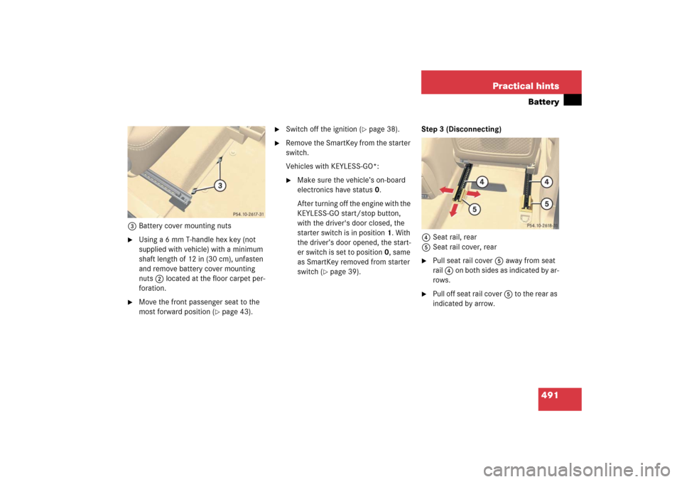
3Battery cover mounting nuts�
Using a 6 mm T-handle hex key (not
supplied with vehicle) with a minimum
shaft length of 12 in (30 cm), unfasten
and remove battery cover mounting
nuts 2 located at the floor carpet per-
foration.
�
Move the front passenger seat to the
most forward position (
�page 43).
�
Switch off the ignition (
�page 38).
�
Remove the SmartKey from the starter
switch.
Vehicles with KEYLESS-GO*:�
Make sure the vehicle’s on-board
electronics have status 0.
After turning off the engine with the
KEYLESS-GO start/stop button,
with the driver's door closed, the
starter switch is in position1. With
the driver’s door opened, the start-
er switch is set to position0, same
as SmartKey removed from starter
switch (
�page 39).Step 3 (Disconnecting)
4Seat rail, rear
5Seat rail cover, rear
�
Pull seat rail cover 5 away from seat
rail 4 on both sides as indicated by ar-
rows.
�
Pull off seat rail cover 5 to the rear as
indicated by arrow.
Page 495 of 561
.
�
Carry out steps 6 to 1 in reverse order
to complete reinstall the battery,
(�page 492) to (
�page 490).
Step 1")
494 Practical hintsBattery�
Carry out step 8 to reconnect the bat-
tery (
�page 493).
�
Carry out steps 6 to 1 in reverse order
to complete reinstall the battery,
(�page 492) to (
�page 490).
Step 11 (Reconnecting)
�
If the battery has been removed, carry
out step 9 (
�page 493) first and then
step 7 (
�page 493), both in reverse
order, before starting the connecting
procedure.
�
Open the driver’s door.
�
Make sure the SmartKey is removed
from the starter switch.
Vehicles with KEYLESS-GO*:�
Make sure the vehicle’s on-board
electronics have status 0.
With the driver’s door opened, the
vehicle’s on-board electronics have
status 0, same as SmartKey re-
moved from the starter switch
(�page 39).
�
Connect the positive lead to the posi-
tive terminal and fasten it’s cover
(�page 493).
�
Connect the negative lead to the nega-
tive terminal (
�page 493).
!Never invert the terminal connections!
iThe following procedures must be car-
ried out following any interruption of
battery power (e.g. due to disconnec-
tion):�
Set the clock (
�page 180).
Vehicles with Modular COMAND
system with navigation module*:
Time and date are set automatical-
ly.
�
Synchronize the door windows
(�page 251).
�
Synchronize the power tilt/sliding
sunroof* (
�page 258).
�
Synchronize the power tilt/sliding
panel* (
�page 262).
�
Synchronize the power folding
exterior rear view mirrors*
(�page 211).
��
Page 501 of 561

500 Practical hintsTowing the vehicle
!
To be certain to avoid additional dam-
age to the vehicle powertrain, however
you should observe the following:�
With damage to the front axle�
raise front axle
�
remove flexible drive shaft be-
tween rear axle and transfer
case
�
With damage to the rear axle�
raise rear axle
�
tow vehicle with wheel lift or
dolly placed under front wheels
�
With damage to the transfer case�
remove flexible drive shaft to
the drive axles
Always install new self-locking nuts
when reinstalling flexible drive shaft.
Warning!
G
If circumstances require towing the vehicle
with all wheels on the ground, always tow
with a tow bar if:�
the engine will not run
�
there is a malfunction in the power
supply or in the vehicle’s electrical sys-
tem
Prior to towing the vehicle with all wheels on
the ground, make sure the SmartKey is in
starter switch position2.
If the SmartKey is left in starter switch
position0 for an extended period of time, it
can no longer be turned in the switch. In this
case, the steering is locked. To unlock,
remove SmartKey from starter switch and
reinsert.
Warning!
G
With the engine not running, there is no
power assistance for the brake and steering
systems. In this case, it is important to keep
in mind that a considerably higher degree of
effort is necessary to brake and steer the
vehicle. Adapt your driving accordingly.iTo signal turns while being towed with
hazard warning flasher in use, turn the
SmartKey in starter switch to
position2 and activate combination
switch for left or right turn signal in
usual manner – only the selected turn
signal will operate.
Upon canceling the turn signal, the
hazard warning flasher will operate
again.
Page 503 of 561

502 Practical hintsTowing the vehicleThe rear towing eye is located behind the
right side cover in the rear bumper panel.
1Towing eye cover
�
Press mark on cover1 as indicated by
the arrow.
�
Lift off cover1 to reveal the threaded
hole for towing eye bolt.
�
Take the towing eye bolt and wheel
wrench from the vehicle toolkit
(�page 455).
�
Screw towing eye bolt in to its stop and
tighten with wheel wrench.
�
After use, unscrew towing eye bolt.
�
Store the towing eye bolt and wheel
wrench back into the vehicle toolkit
(�page 455).
�
Engage cover1 at top and press at
bottom.
Stranded vehicle
Freeing a stranded vehicle, on which the
wheels are dug into sand or mud, should
be done with the greatest of care, especial-
ly if the vehicle is heavily loaded.
Avoid pulling the vehicle abruptly or diago-
nally, since it could result in damage to the
chassis alignment.
Never try to free a vehicle that is still cou-
pled to a trailer.
If possible, a vehicle equipped with trailer
hitch receiver should be pulled backward
in its own previously made tracks.
Warning!
G
In order to avoid possible serious burns or
injury, use extreme caution when removing
the cover, because the rear exhaust pipe is
extremely hot.
Page 511 of 561
510 Technical dataIdentification labels1Certification label (on driver’s B-pillar)
Example certification label R 5002Paintwork code
3Vehicle Identification Number (VIN)
The vehicle identification number (VIN) is
also embossed underneath the passen-
ger-side seat in the second seat row.4Second-row seat
5Carpet
6Vehicle Identification Number (VIN)
�
Move second-row seat 4 on passen-
ger side to the rear as far as possible
(�page 137).
�
Fold carpet 5 in direction of arrow.
You may have to cut the perforated car-
pet using a sharp object, e. g. a knife.
iData shown on certification label are
for illustration purposes only. These
data are specific to each vehicle and
may vary from data shown in the illus-
tration. Refer to certification label on
vehicle for actual data specific to your
vehicle.
iWhen ordering parts, please specify
vehicle identification and engine num-
ber.
Page 520 of 561
519 Technical data
Main Dimensions
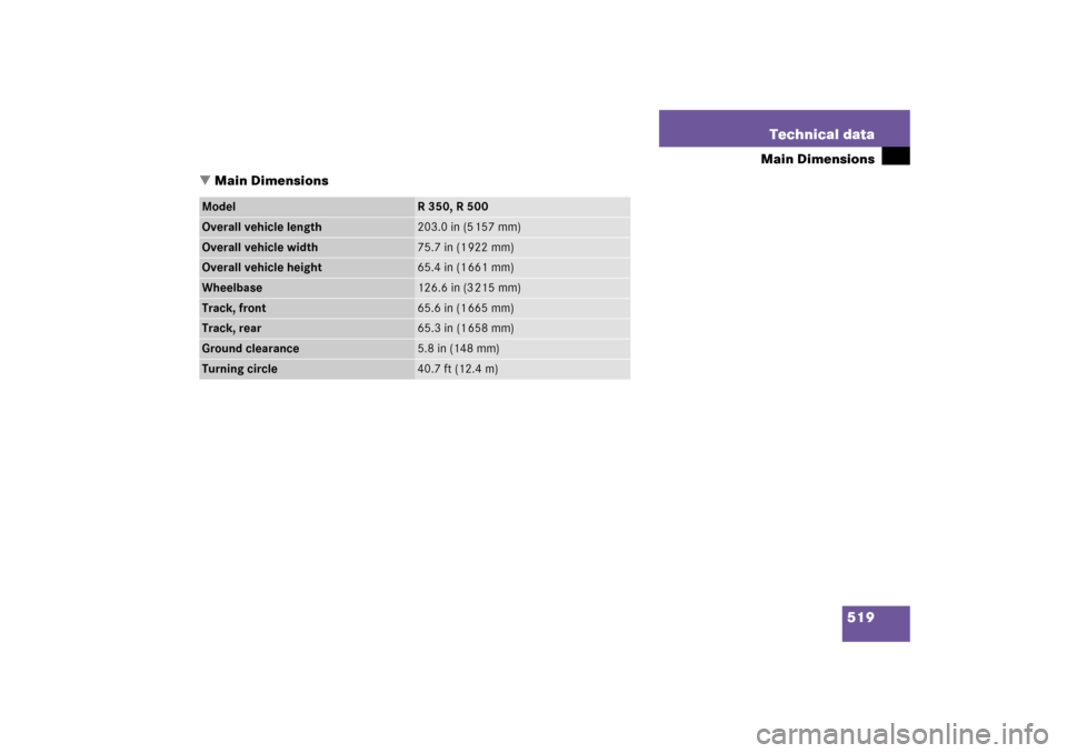
�Main Dimensions
Model
R 350, R 500
Overall vehicle length
203.0in (5157mm)
Overall vehicle width
75.7 in (1 922 mm)
Overall vehicle height
65.4 in (1 661 mm)
Wheelbase
126.6 in (3 215 mm)
Track, front
65.6 in (1 665 mm)
Track, rear
65.3 in (1 658 mm)
Ground clearance
5.8 in (148 mm)
Turning circle
40.7 ft (12.4 m)
Page 522 of 561
521 Technical data
Fuels, coolants, lubricants, etc.
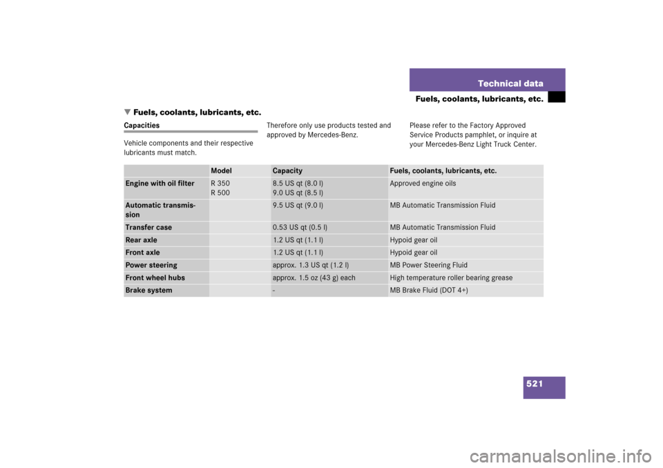
�Fuels, coolants, lubricants, etc.
Capacities
Vehicle components and their respective
lubricants must match.Therefore only use products tested and
approved by Mercedes-Benz.Please refer to the Factory Approved
Service Products pamphlet, or inquire at
your Mercedes-Benz Light Truck Center.
Model
Capacity
Fuels, coolants, lubricants, etc.
Engine with oil filter
R 350
R 500
8.5 US qt (8.0 l)
9.0 US qt (8.5 l)
Approved engine oils
Automatic transmis-
sion
9.5 US qt (9.0 l)
MB Automatic Transmission Fluid
Transfer case
0.53 US qt (0.5 l)
MB Automatic Transmission Fluid
Rear axle
1.2 US qt (1.1 l)
Hypoid gear oil
Front axle
1.2 US qt (1.1 l)
Hypoid gear oil
Power steering
approx. 1.3 US qt (1.2 l)
MB Power Steering Fluid
Front wheel hubs
approx. 1.5 oz (43 g) each
High temperature roller bearing grease
Brake system
-
MB Brake Fluid (DOT 4+)

Example certification label R 5002Paintwork code
3Vehicle Identification Number (VIN)
The vehicle identification nu")