Page 461 of 561

460 Practical hintsUnlocking / locking in an emergencyUnlocking the driver’s door
1Unlocking
2Mechanical key�
Insert mechanical key 2 into the
driver’s door lock until it stops.
�
Turn mechanical key 2 counterclock-
wise to position1 and hold it there.
�
Pull the door handle until the locking
knob moves up.
The driver’s door is unlocked.
�
Pull the door handle once more to open
the driver’s door.
Locking the vehicle
If you cannot lock the vehicle with the
SmartKey or KEYLESS-GO*, lock the vehi-
cle carrying out the following steps.�
Close the front passenger door, the
rear right door and the tailgate.
�
Open the driver’s door and the rear left
door.
�
Press the central locking switch on the
driver’s door (
�page 131).
The locking knobs of the front passen-
ger door and the rear doors move
down.
If the vehicle battery is disconnected or
drained:
�
Press down the locking knobs of
the front passenger door and the
rear doors manually.
�
Exit the vehicle.
�
Close the driver’s door.
�
Enter the vehicle through the rear left
door.
�
Press down the locking knob of the
driver’s door.
�
Exit the vehicle.
�
Close the rear left door.
The vehicle is locked.!To prevent inadvertent lockout, make
sure to have the SmartKey or SmartKey
with KEYLESS-GO* with you before
proceeding with the next step. The next
step will lock the vehicle.
Page 463 of 561

462 Practical hintsOpening / closing in an emergencyPower tilt/sliding sunroof*
You can open or close the tilt/sliding
sunroof manually should an electrical
malfunction occur.
The tilt/sliding sunroof drive is located
behind a cover on the overhead control
panel.
1Cover�
Remove the SmartKey from the starter
switch.Vehicles with KEYLESS-GO*:
�
Turn off the engine by pressing the
KEYLESS-GO start/stop button
(�page 66).
�
Open the driver’s door (this puts
the starter switch to position0,
same as with the SmartKey re-
moved from starter switch). The
driver’s door can then be closed
again.
�
Press on cover1 at the position indi-
cated by the arrow.
�
Take off cover 1.
2Crank
�
Take crank 2 out of the Operator’s
Manual pouch.
�
Insert crank2 into hole.
�
Turn crank2 clockwise to�
slide sunroof closed
�
raise sunroof at the rear
�
Turn crank2 counterclockwise to�
slide sunroof open
�
lower sunroof at the rear
iTurn crank2 slowly and smoothly.
The tilt/sliding sunroof must be syn-
chronized if it has been operated man-
ually (
�page 258).
iThe panorama roof with power
tilt/sliding panel* cannot be operated
as described. Contact an authorized
Mercedes-Benz Light Truck Center.
Page 467 of 561
466 Practical hintsReplacing bulbsFront lamps Rear lamps
Lamp
Type
1
Parking/standing lamp
W 5 W
2
Turn signal lamp
PY 21 W
3
Additional turn signal
lamp
LED
4
Headlamps:
Low beam
H7 (55W)
Bi-Xenon headlamps*:
Low beam
1
1Vehicles with Bi-Xenon* headlamps: Do not
replace the Bi-Xenon bulbs yourself. Contact an
authorized Mercedes-Benz Light Truck Center.
D2S-35 W
5
Headlamps:
High beam/high beam
flasher
H7 (55W)
Bi-Xenon headlamps*:
High beam/high beam
flasher spot lamp
H7 (55W)
6
Sidemarker lamp
WY 5 W
7
Corner-illuminating
front fog lamp*
H11 (55W)
Lamp
Type
8
High-mounted brake
lamp
LED
9
Tail, brake, and
sidemarker lamp
P 21 W
a
Turn signal lamp
PY 21 W
b
Backup lamp
P 21 W
c
Rear fog lamp (driver’s
side only)
P 21 W
d
License plate lamps
C 5 W
Page 468 of 561

467 Practical hints
Replacing bulbs
Notes on bulb replacement�
Only use 12-volt bulbs of the same type
and with the specified watt rating.
�
Switch the lights off before changing a
bulb to prevent short circuits.
�
Always use a clean lint-free cloth when
handling bulbs.
�
Your hands should be dry and free of oil
and grease.
�
If the newly installed bulb does not
come on, visit an authorized
Mercedes-Benz Light Truck Center.Have the LEDs and bulbs for the following
lamps replaced by an authorized
Mercedes-Benz Light Truck Center:
�
the additional turn signal lamps in the
exterior rear view mirrors
�
the high mounted brake lamp
�
the Bi-Xenon* low beam lamps
�
the Bi-Xenon high beam flasher spot-
light*
�
the front sidemarker lamps
Warning!
G
Bulbs and bulb sockets can be very hot.
Allow the lamp to cool down before chang-
ing a bulb.
Keep bulbs out of reach of children.
Halogen lamps contain pressurized gas.
A bulb can explode if you:�
touch or move it when hot
�
drop the bulb
�
scratch the bulb
Wear eye and hand protection.
Because of high voltage in Xenon lamps, it is
dangerous to replace the bulb or repair the
lamp and its components. We recommend
that you have such work done by a qualified
technician.
Page 473 of 561

472 Practical hintsReplacing bulbs�
Turn bulb socket 5 clockwise until it
engages.
�
Insert corner-illuminating front fog
lamp 1 back into bumper.
�
Fasten retaining screws4.
�
Reinsert cover 2 and press it in until it
engages.
�
Fasten retaining screw3.Additional turn signal lamps bulbs
The additional turn signal lamps in the
exterior rear view mirrors have LEDs.
If a malfunction occurs or LEDs fail to func-
tion, the entire turn signal unit must be re-
placed. Have the turn signal unit replaced
by an authorized Mercedes-Benz Light
Truck Center.
Front sidemarker lamp bulbs
Since replacing the sidemarker lamp bulbs
is a technically highly demanding process,
we recommend you have the sidemarker
lamp bulbs replaced by an authorized
Mercedes-Benz Light Truck Center.
Replacing bulbs for rear lamps
Before you start to replace a bulb for a rear
lamp, do the following first:�
Turn the combination switch to
positionM (
�page 147).
Tail lamp unit
�
Open the tailgate (
�page 122).
iTo access the tail lamp units, you have
to remove the cover in the correspond-
ing side trim panel of the cargo com-
partment.
��
Page 477 of 561

476 Practical hintsReplacing wiper bladesInstalling
1Wiper blade
2Attachment
3Guide tab
4Opening�
With guide tab 3 sliding into opening
4, place wiper blade 1 onto wiper
arm in direction of arrow.
�
Fold wiper blade 1 towards wiper
arm.
Tabs 2 must engage into both recess-
es of attachment 2.
�
Check whether the wiper blade is
securely fastened.
�
Fold the wiper arm backward to rest on
the windshield.
Make sure to hold on to the wiper when
folding the wiper arm back.
Rear wiper bladeWarning!
G
For safety reasons, switch off wipers and
remove SmartKey from starter switch
(vehicles with KEYLESS-GO*: Make sure the
vehicle’s on-board electronics have
status0) before replacing a wiper blade.
Otherwise the motor could suddenly turn on
and cause injury.!Hold on to the wiper when folding the
wiper arm back. If released, the force
of the impact from the tensioning
spring could crack the rear window.
Do not allow the wiper arms to contact
the rear window glass without a wiper
blade inserted.
Page 478 of 561

477 Practical hints
Replacing wiper blades
Removing�
Remove the SmartKey from the starter
switch.
or
�
Vehicles with KEYLESS-GO*:
Make sure the vehicle’s on-board
electronics have status0 (
�page 39).
�
Fold wiper arm 1 away from the rear
window until it engages.
1Wiper arm
2Wiper blade
�
Turn wiper blade2 to form a right an-
gle with wiper arm 1 as shown.
�
Hold wiper arm 1 and disengage wip-
er blade 2 by carefully sliding it in
direction of arrow.
�
Remove wiper blade 2.Installing
1Wiper arm
2Wiper blade
�
Insert wiper blade 2 into wiper
arm1.
�
Hold wiper arm 1 and engage wiper
blade 2 by pushing it in direction of ar-
row until it locks into place.
�
Check whether the wiper blade is
securely fastened.
�
Fold the wiper arm to rest on the rear
window.
Make sure to hold on to the wiper when
folding the wiper arm back. Make sure the wiper blades are proper-
ly installed. Improperly installed wiper
blades may cause rear window dam-
age.
For your convenience, we recommend
that you have this work carried out by
an authorized Mercedes-Benz Light
Truck Center.
Page 481 of 561
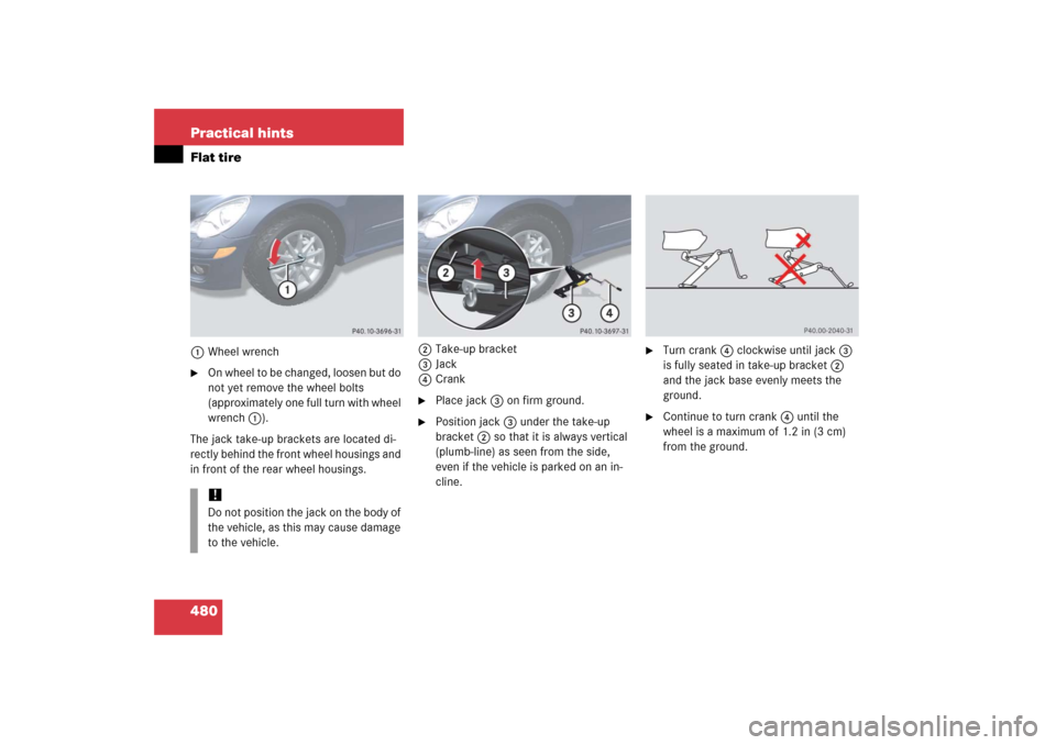
480 Practical hintsFlat tire1Wheel wrench�
On wheel to be changed, loosen but do
not yet remove the wheel bolts
(approximately one full turn with wheel
wrench 1).
The jack take-up brackets are located di-
rectly behind the front wheel housings and
in front of the rear wheel housings.2Take-up bracket
3Jack
4Crank
�
Place jack 3 on firm ground.
�
Position jack3 under the take-up
bracket2 so that it is always vertical
(plumb-line) as seen from the side,
even if the vehicle is parked on an in-
cline.
�
Turn crank4 clockwise until jack 3
is fully seated in take-up bracket2
and the jack base evenly meets the
ground.
�
Continue to turn crank 4 until the
wheel is a maximum of 1.2 in (3 cm)
from the ground.
!Do not position the jack on the body of
the vehicle, as this may cause damage
to the vehicle.

Bi-Xenon h")