Page 431 of 521

430 Practical hintsReplacing SmartKey batteries�
Pull battery compartment3
(�page 429) out of the housing in di-
rection of arrow.
�
Remove the batteries4 in direction of
arrow.
4Battery
5Contact spring
�
Using a lint-free cloth, insert new
batteries4 under the contact spring
5 with the positive terminal (+) side
facing up.
�
Return battery compartment3
(�page 429) into housing until it locks
into place.
�
Slide mechanical key1 (
�page 429)
back into the SmartKey.
�
Check the operation of the SmartKey.
SmartKey with KEYLESS-GO*
Replacement batteries: Lithium, type
CR 2025 or equivalent.�
Remove the mechanical key
(�page 424).
�
Insert the mechanical key1
(�page 429) in side opening and push
grey slide2 (
�page 429).
Battery compartment3 (
�page 429)
is unlatched.
�
Pull battery compartment3
(�page 429) out of the housing in di-
rection of arrow.1Battery
2Tilt battery up
3Mechanical key
�
Using mechanical key3 apply pres-
sure to position2.
Battery1 tilts up slightly.
�
Pull out batteries1 in direction of ar-
row.
�
Using a lint-free cloth, insert new bat-
teries with the positive terminal (+) side
facing up.
�
Return battery compartment3
(�page 429) into housing until it locks
into place.
��
Page 435 of 521

434 Practical hintsReplacing bulbsReplacing bulbs for front lamps
1Housing cover for low beam halogen or
Bi-Xenon* headlamp2Bulb socket for high beam head-
lamp/high beam flasher bulb
3Bulb socket for parking and standing
lamp bulb
4Bulb socket for low beam headlamp
bulb (halogen headlamps only)
5Bulb socket for turn signal lamp bulb
Before you start to replace a bulb for a
front lamp, do the following first:
�
Turn the exterior lamp switch to
positionM (
�page 143).
�
Open the hood (
�page 315).Low beam bulb (halogen headlamps
only)
�
Turn housing cover1 counterclock-
wise and remove it.
�
Turn bulb socket4 with the bulb
counterclockwise and remove it.
�
Pull the bulb out of bulb socket4.
�
Press the new bulb gently into bulb
socket4.
�
Place bulb socket5 back into the
lamp and turn it clockwise until it en-
gages.
�
Align housing cover1 and turn it
clockwise until it engages.
Warning!
G
Do not remove the cover1 for the
Bi-Xenon* headlamp. Because of high
voltage in Bi-Xenon* lamps, it is dangerous
to replace the bulb or repair the lamp and its
components. We recommend that you have
such work done by a qualified technician.
Page 436 of 521

435 Practical hints
Replacing bulbs
High beam bulb/high beam flasher
bulb (halogen headlamps)/high beam
flasher bulb (Bi-Xenon* headlamps)�
Turn bulb socket2 with the bulb
counterclockwise and remove it.
�
Pull the bulb out of bulb socket2.
�
Press the new bulb gently into bulb
socket2.
�
Place bulb socket2 back into the
lamp and turn it clockwise until it en-
gages.Front turn signal lamp bulb
�
Turn bulb socket5 with the bulb
counterclockwise and remove it.
�
Press gently onto the bulb and turn
counterclockwise out of bulb
socket5.
�
Press the new bulb gently into bulb
socket5 and turn clockwise until it
engages.
�
Place bulb socket5 back into the
lamp and turn it clockwise until it en-
gages.
Parking and standing lamp bulb
�
Turn bulb socket3 with the bulb
counterclockwise and remove it.
�
Pull the bulb out of bulb socket3.
�
Press the new bulb gently into bulb
socket3.
�
Place bulb socket3 back into the
lamp and turn clockwise until it engag-
es.Additional turn signal lamp bulbs
The additional turn signal lamps in the
exterior rear view mirrors have LEDs.
If a malfunction occurs or LEDs fail to func-
tion, the entire turn signal unit must be re-
placed. Have the turn signal unit replaced
by an authorized Mercedes-Benz Center.
Front side marker lamp bulbs
Since replacing the side marker lamp bulbs
is a technically highly demanding process,
we recommend you have the side marker
lamp bulbs replaced by an authorized
Mercedes-Benz Center.
Page 439 of 521

438 Practical hintsReplacing wiper bladesInstalling front wiper blades�
Slide the wiper blade onto wiper arm
until it locks in place.
�
Rotate the wiper blade into position
parallel to wiper arm.
�
Fold the wiper arm backward to rest on
the windshield. Make sure you hold on
to the wiper when folding the wiper arm
back.
Removing rear wiper blade�
Fold the wiper arm forward until it en-
gages.
!Never open the hood when the wiper
arm is folded forward.
Hold on to the wiper when folding the
wiper arm back. If released, the force
of the impact from the tensioning
spring could crack the windshield.
Do not allow the wiper arms to contact
the windshield glass without a wiper
blade inserted.
Make certain that the wiper blades are
properly installed. Improperly installed
wiper blades may cause windshield
damage.
For your convenience, we recommend
that you have this work carried out by
an authorized Mercedes-Benz Center.
Warning!
G
For safety reasons, switch off wipers and
remove SmartKey from starter switch (vehi-
cles with KEYLESS-GO*: Make sure the
vehicle’s on-board electronics have
status0) before replacing a wiper blade.
Otherwise the motor could suddenly turn on
and cause injury.
Page 440 of 521
439 Practical hints
Replacing wiper blades
1Wiper blade
2Tab
3Attachment
4Removing�
Turn the wiper blade1 at a right angle
to wiper arm.
�
Press tab2 down and push wiper
blade1 downward in direction of
arrow4.
�
Remove wiper blade1.
Installing rear wiper blade
1Wiper blade
2Tab
3Attachment
4Installing�
Slide the wiper blade1 into
attachment3 in direction of
arrow4.
�
Let tab2 latch into attachment3
until it locks in place.
�
Check if the wiper blade is securely fas-
tened.
�
Fold the wiper arm backward to rest on
the rear windshield.
Make sure you hold on to the wiper arm
when folding it back.
Page 446 of 521

445 Practical hints
Flat tire
Mounting the spare wheel Preparing the vehicle
Prepare the vehicle as described
(
�page 440).
Vehicles with Minispare wheel
(except E 55 AMG):
�
Take the Minispare wheel, wheel
wrench and the jack out of the cargo
compartment (
�page 422).
Vehicles with collapsible tire (E 55 AMG
without folding third row seat only):
�
Take the collapsible tire, wheel wrench,
jack and electric air pump out of the
cargo compartment (
�page 422).Lifting the vehicle
�
Prevent the vehicle from rolling away
by blocking wheels with wheel chocks
or other sizable objects.
One wheel chock is included with the
vehicle tool kit (
�page 419).
When changing wheel on a level surface:
�
Place the wheel chock in front of and
another sizable object behind the
wheel that is diagonally opposite to the
wheel being changed.
Always try lifting the vehicle using the jack
on a level surface. However, should
circumstances require you to do so on a
hill, place the wheel chock and the other
sizeable object as follows:
�
Place the wheel chock and another siz-
able object on the downhill side block-
ing both wheels of the axle not being
worked on.
Warning!
G
The dimensions of the spare wheel
(Minispare or collapsible tire) are different
from those of the road wheels. As a result,
the vehicle handling characteristics change
when driving with a spare wheel mounted.
Adapt your driving style accordingly.
The spare wheel is for temporary use only.
When driving with spare wheel mounted,
ensure proper tire pressure and do not ex-
ceed a vehicle speed of 50 mph (80 km/h).
Drive to the nearest Mercedes-Benz Center
as soon as possible to have the spare wheel
replaced with a regular road wheel.
Never operate the vehicle with more than
one spare wheel mounted.
Do not switch off the ESP
® when a
Minispare wheel or spare wheel with
collapsible tire is mounted.
��
Page 447 of 521

446 Practical hintsFlat tire
�
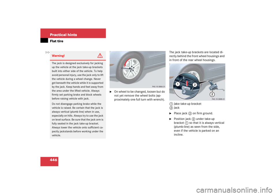
On wheel to be changed, loosen but do
not yet remove the wheel bolts (ap-
proximately one full turn with wrench). The jack take-up brackets are located di-
rectly behind the front wheel housings and
in front of the rear wheel housings.
1Jake take-up bracket
2Jack
�
Place jack2 on firm ground.
�
Position jack2 under take-up
bracket1 so that it is always vertical
(plumb-line) as seen from the side,
even if the vehicle is parked on an
incline.
Warning!
G
The jack is designed exclusively for jacking
up the vehicle at the jack take-up brackets
built into either side of the vehicle. To help
avoid personal injury, use the jack only to lift
the vehicle during a wheel change. Never
get beneath the vehicle while it is supported
by the jack. Keep hands and feet away from
the area under the lifted vehicle. Always
firmly set parking brake and block wheels
before raising vehicle with jack.
Do not disengage parking brake while the
vehicle is raised. Be certain that the jack is
always vertical (plumb line) when in use,
especially on hills. Always try to use the jack
on level surface. Be sure that the jack arm is
fully seated in the jack take-up bracket.
Always lower the vehicle onto sufficient ca-
pacity jackstands before working under the
vehicle.
��
Page 451 of 521

450 Practical hintsFlat tire�
Press0 on electric air pump switch 2.
�
Turn the SmartKey in the starter switch
to position0.
�
If the tire pressure is above 51 psi
(3.5 bar), release excess tire pressure
using the vent screw.
�
Detach the electric air pump.
�
Store the electrical plug 3 and the air
hose 4 behind the flap 1 and place
the electric air pump back in the desig-nated storage space underneath the
cargo compartment floor
(
�page 419).
Lowering the vehicle
�
Lower vehicle by turning crank coun-
terclockwise until vehicle is resting ful-
ly on its own weight.
�
Remove the jack.
1-5 Wheel bolts
�
Tighten the five wheel bolts evenly, fol-
lowing the diagonal sequence illustrat-
ed (1 to 5), until all bolts are tight.
Observe a tightening torque of 96 lb-ft
(130 Nm).Before storing the jack, it should be fully
collapsed, with handle folded in (storage
position).
�
Store the jack and the other vehicle
tools in the designated storage space
underneath the cargo compartment
floor (
�page 419).
Warning!
G
Follow recommend inflation pressures.
Do not overinflate tires. Overinflating tires
can result in sudden deflation (blowout) be-
cause they are more likely to become punc-
tured or damaged by road debris, potholes,
etc.
Do not underinflate tires. Underinflated tires
wear unevenly, adversely affect handling
and fuel economy, and are more likely to fail
from being overheated.
Warning!
G
Have the tightening torque checked after
changing a wheel. The wheels could come
loose if they are not tightened to a torque of
96 lb-ft (130 Nm).iWrap the damaged wheel in the protec-
tive film that comes with the spare
wheel and put the wheel in the cargo
compartment.
Do not activate the tire pressure moni-
toring system* until the depressurized
tire is no longer in the vehicle.
��