Page 1622 of 3383
DTC P0453 EVAP CONTROL SYSTEM PRESSURE SENSOREC-411
C
DE
F
G H
I
J
K L
M A
EC
Revision: November 2009 2006 QX56
DTC P0453 EVAP CONTROL SYSTEM PRESSURE SENSORPFP:25085
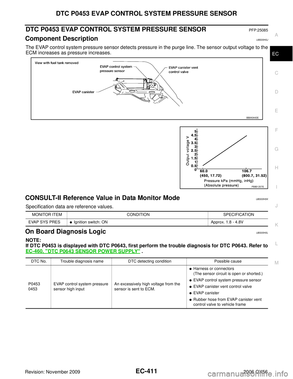
Component DescriptionUBS00H5J
The EVAP control system pressure sensor detects pressure in the purge line. The sensor output voltage to the
ECM increases as pressure increases.
CONSULT-II Reference Value in Data Monitor ModeUBS00H5K
Specification data are reference values.
On Board Diagnosis LogicUBS00H5L
NOTE:
If DTC P0453 is displayed with DTC P0643, first perform the trouble diagnosis for DTC P0643. Refer to
EC-460, "
DTC P0643 SENSOR POWER SUPPLY" .
BBIA0443E
PBIB1207E
MONITOR ITEMCONDITION SPECIFICATION
EVAP SYS PRES
�Ignition switch: ON Approx. 1.8 - 4.8V
DTC No. Trouble diagnosis nameDTC detecting conditionPossible cause
P0453
0453 EVAP control system pressure
sensor high input An excessively high voltage from the
sensor is sent to ECM.
�Harness or connectors
(The sensor circuit is open or shorted.)
�EVAP control system pressure sensor
�EVAP canister vent control valve
�EVAP canister
�Rubber hose from EVAP canister vent
control valve to vehicle frame
Page 1623 of 3383
EC-412Revision: November 2009
DTC P0453 EVAP CONTROL SYSTEM PRESSURE SENSOR
2006 QX56
DTC Confirmation ProcedureUBS00H5M
NOTE:
If DTC Confirmation Procedure has been previously conducted, always turn ignition switch OFF and wait at
least 10 seconds before conducting the next test.
TESTING CONDITION:
Always perform test at a temperature of 5°C (41 °F) or more.
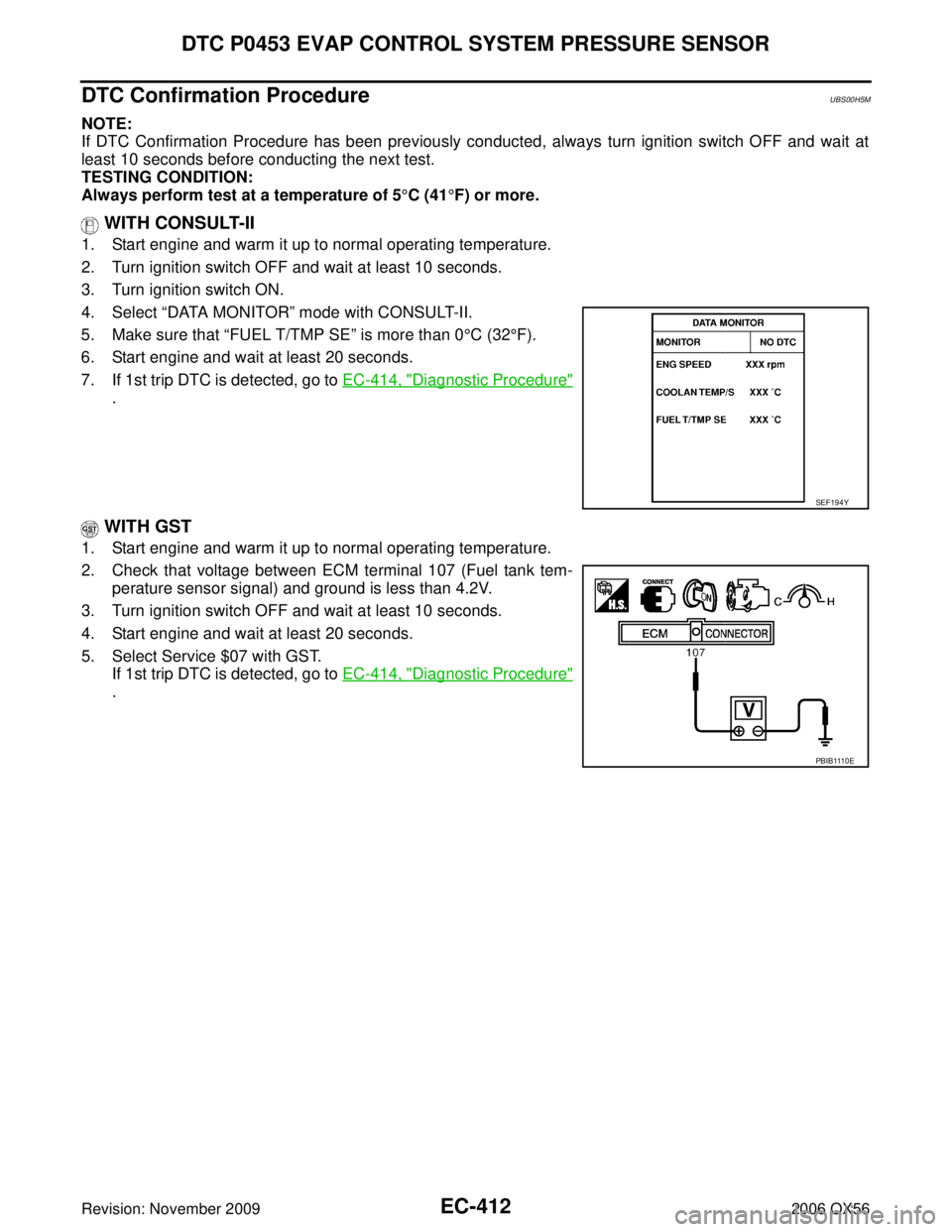
WITH CONSULT-II
1. Start engine and warm it up to normal operating temperature.
2. Turn ignition switch OFF and wait at least 10 seconds.
3. Turn ignition switch ON.
4. Select “DATA MONITOR ” mode with CONSULT-II.
5. Make sure that “FUEL T/TMP SE ” is more than 0°C (32 °F).
6. Start engine and wait at least 20 seconds.
7. If 1st trip DTC is detected, go to EC-414, "
Diagnostic Procedure"
.
WITH GST
1. Start engine and warm it up to normal operating temperature.
2. Check that voltage between ECM terminal 107 (Fuel tank tem-
perature sensor signal) and ground is less than 4.2V.
3. Turn ignition switch OFF and wait at least 10 seconds.
4. Start engine and wait at least 20 seconds.
5. Select Service $07 with GST. If 1st trip DTC is detected, go to EC-414, "
Diagnostic Procedure"
.
SEF194Y
PBIB1110E
Page 1625 of 3383
EC-414Revision: November 2009
DTC P0453 EVAP CONTROL SYSTEM PRESSURE SENSOR
2006 QX56
Specification data are reference values and are measured between each terminal and ground.
CAUTION:
Do not use ECM ground terminals when measuring input/output voltage. Doing so may result in dam-
age to the ECM's transistor. Use a ground other than ECM terminals, such as the ground.
Diagnostic ProcedureUBS00H5O
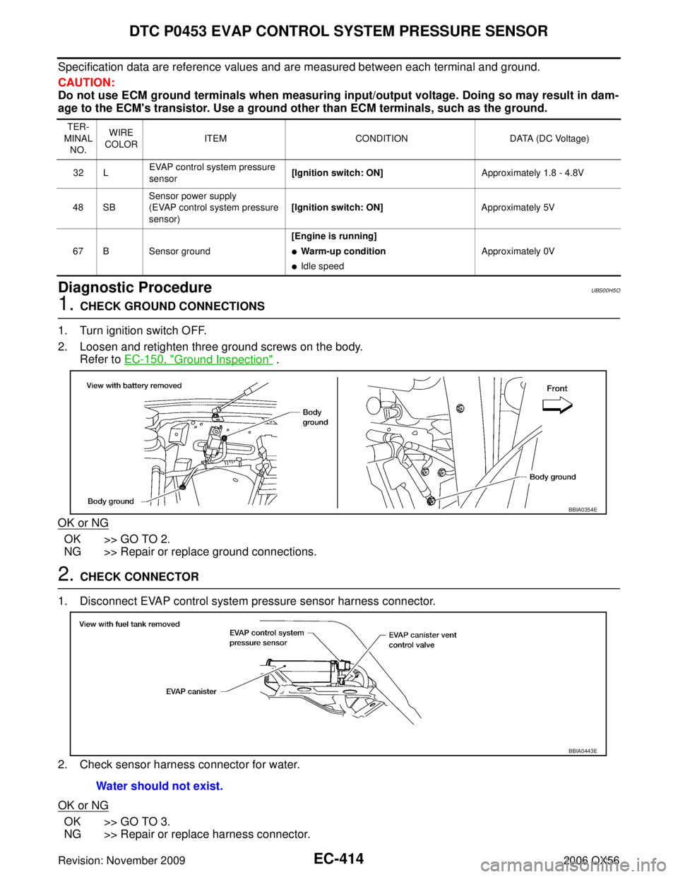
1. CHECK GROUND CONNECTIONS
1. Turn ignition switch OFF.
2. Loosen and retighten three ground screws on the body. Refer to EC-150, "
Ground Inspection" .
OK or NG
OK >> GO TO 2.
NG >> Repair or replace ground connections.
2. CHECK CONNECTOR
1. Disconnect EVAP control system pressure sensor harness connector.
2. Check sensor harness connector for water.
OK or NG
OK >> GO TO 3.
NG >> Repair or replace harness connector.
TER-
MINAL NO. WIRE
COLOR ITEM
CONDITION DATA (DC Voltage)
32 L EVAP control system pressure
sensor [Ignition switch: ON]
Approximately 1.8 - 4.8V
48 SB Sensor power supply
(EVAP control system pressure
sensor) [Ignition switch: ON]
Approximately 5V
67 B Sensor ground [Engine is running]
�Warm-up condition
�Idle speed
Approximately 0V
BBIA0354E
Water should not exist.
BBIA0443E
Page 1626 of 3383
DTC P0453 EVAP CONTROL SYSTEM PRESSURE SENSOREC-415
C
DE
F
G H
I
J
K L
M A
EC
Revision: November 2009 2006 QX56
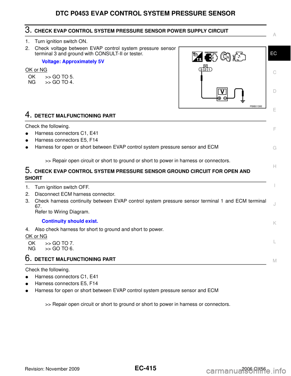
3. CHECK EVAP CONTROL SYSTEM PRESSURE SENSOR POWER SUPPLY CIRCUIT
1. Turn ignition switch ON.
2. Check voltage between EVAP control system pressure sensor terminal 3 and ground with CONSULT-II or tester.
OK or NG
OK >> GO TO 5.
NG >> GO TO 4.
4. DETECT MALFUNCTIONING PART
Check the following.
�Harness connectors C1, E41
�Harness connectors E5, F14
�Harness for open or short between EVAP control system pressure sensor and ECM
>> Repair open circuit or short to ground or short to power in harness or connectors.
5. CHECK EVAP CONTROL SYSTEM PRESSURE SENSOR GROUND CIRCUIT FOR OPEN AND
SHORT1. Turn ignition switch OFF.
2. Disconnect ECM harness connector.
3. Check harness continuity between EVAP control system pressure sensor terminal 1 and ECM terminal 67.
Refer to Wiring Diagram.
4. Also check harness for short to ground and short to power.
OK or NG
OK >> GO TO 7.
NG >> GO TO 6.
6. DETECT MALFUNCTIONING PART
Check the following.
�Harness connectors C1, E41
�Harness connectors E5, F14
�Harness for open or short between EVAP control system pressure sensor and ECM
>> Repair open circuit or short to ground or short to power in harness or connectors.
Voltage: Approximately 5V
PBIB0138E
Continuity should exist.
Page 1629 of 3383
EC-418Revision: November 2009
DTC P0453 EVAP CONTROL SYSTEM PRESSURE SENSOR
2006 QX56
Component InspectionUBS00H5P
EVAP CONTROL SYSTEM PRESSURE SENSOR
1. Remove EVAP control system pressure sensor with its harness connector connected from EVAP canister.Always replace O-ring with a new one.
2. Install a vacuum pump to EVAP control system pressure sensor.
3. Turn ignition switch ON and check output voltage between ECM terminal 32 and ground under the following conditions.
CAUTION:
�Always calibrate the vacuum pump gauge when using it.
�Do not apply below -93.3 kPa (-700 mmHg, -27.56 inHg) or
pressure over 101.3 kPa (760 mmHg, 29.92 inHg).
4. If NG, replace EVAP control system pressure sensor.
Applied vacuum kPa (mmHg, inHg) Voltage V
Not applied 1.8 - 4.8
-26.7 (-200, -7.87) 2.1 to 2.5V lower than above value
PBIB1173E
Page 1631 of 3383
EC-420Revision: November 2009
DTC P0455 EVAP CONTROL SYSTEM
2006 QX56
DTC Confirmation ProcedureUBS00H5R
CAUTION:
Never remove fuel filler cap during the DTC Confirmation Procedure.
NOTE:
�Make sure that EVAP hoses are connected to EVAP canister purge volume control solenoid valve
properly.
�If DTC Confirmation Procedure has been previously conducted, always turn ignition switch OFF and wait
at least 10 seconds before conducting the next test.
TESTING CONDITION:
�Perform “DTC WORK SUPPORT” when the fuel level is between 1/4 and 3/4 full, and vehicle is
placed on flat level surface.
�Open engine hood before conducting the following procedures.
WITH CONSULT-II
1. Tighten fuel filler cap securely until ratcheting sound is heard.
2. Turn ignition switch ON.
3. Turn ignition switch OFF and wait at least 10 seconds.
4. Turn ignition switch ON and select “DATA MONITOR” mode with CONSULT-II.
5. Make sure that the following conditions are met. COOLAN TEMP/S: 0 - 70 °C (32 - 158 °F)
INT/A TEMP SE: 0 - 60 °C (32 - 140 °F)
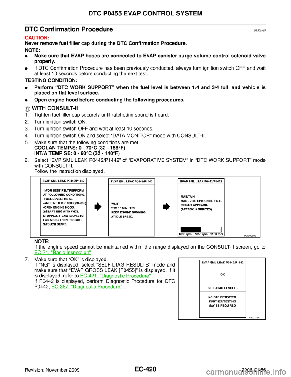
6. Select “EVP SML LEAK P0442/P1442 ” of “EVAPORATIVE SYSTEM ” in “DTC WORK SUPPORT ” mode
with CONSULT-II.
Follow the instruction displayed.
NOTE:
If the engine speed cannot be maintained within the range displayed on the CONSULT-II screen, go to
EC-71, "
Basic Inspection" .
7. Make sure that “OK ” is displayed.
If “NG ” is displayed, select “SELF-DIAG RESULTS” mode and
make sure that “EVAP GROSS LEAK [P0455] ” is displayed. If it
is displayed, refer to EC-421, "
Diagnostic Procedure" .
If P0442 is displayed, perform Diagnostic Procedure for DTC
P0442, EC-367, "
Diagnostic Procedure" .
PBIB0829E
SEC763C
Page 1632 of 3383
DTC P0455 EVAP CONTROL SYSTEMEC-421
C
DE
F
G H
I
J
K L
M A
EC
Revision: November 2009 2006 QX56
WITH GST
NOTE:
Be sure to read the explanation of EC-58, "
Driving Pattern" before driving vehicle.
1. Start engine.
2. Drive vehicle according to EC-58, "
Driving Pattern" .
3. Stop vehicle.
4. Turn ignition switch OFF, wait at least 10 seconds and then turn ON.
5. Select Service $07 with GST.
�If P0455 is displayed on the screen, go to EC-421, "Diagnostic Procedure" .
�If P0442 is displayed on the screen, go to EC-367, "Diagnostic Procedure" .
�If P0441 is displayed on the screen, go to EC-362, "Diagnostic Procedure" .
Diagnostic ProcedureUBS00H5S
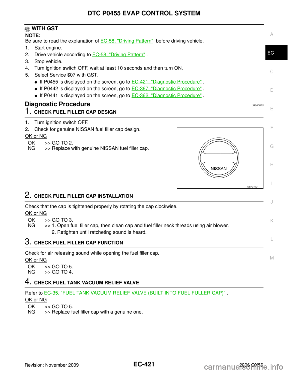
1. CHECK FUEL FILLER CAP DESIGN
1. Turn ignition switch OFF.
2. Check for genuine NISSAN fuel filler cap design.
OK or NG
OK >> GO TO 2.
NG >> Replace with genuine NISSAN fuel filler cap.
2. CHECK FUEL FILLER CAP INSTALLATION
Check that the cap is tightened properly by rotating the cap clockwise.
OK or NG
OK >> GO TO 3.
NG >> 1. Open fuel filler cap, then clean cap and fuel filler neck threads using air blower. 2. Retighten until ratcheting sound is heard.
3. CHECK FUEL FILLER CAP FUNCTION
Check for air releasing sound while opening the fuel filler cap.
OK or NG
OK >> GO TO 5.
NG >> GO TO 4.
4. CHECK FUEL TANK VACUUM RELIEF VALVE
Refer to EC-35, "
FUEL TANK VACUUM RELIEF VALVE (BUILT INTO FUEL FULLER CAP)" .
OK or NG
OK >> GO TO 5.
NG >> Replace fuel filler cap with a genuine one.
SEF915U
Page 1634 of 3383
DTC P0455 EVAP CONTROL SYSTEMEC-423
C
DE
F
G H
I
J
K L
M A
EC
Revision: November 2009 2006 QX56
9. CHECK FOR EVAP LEAK
With CONSULT-II
1. Turn ignition switch ON.
2. Select “EVAP SYSTEM CLOSE ” of “WORK SUPPORT ” mode
with CONSULT-II.
3. Touch “START” and apply pressure into the EVAP line until the
pressure indicator reaches the middle of the bar graph.
CAUTION:
�Do not use compressed air or a high pressure pump.
�Do not exceed 4.12 kPa (0.042 kg/cm2 , 0.6 psi) of pres-
sure in the system.
4. Using EVAP leak detector, locate the EVAP leak. For the leak detector, refer to the instruction manual for more details.
Refer to EC-33, "
EVAPORATIVE EMISSION LINE DRAWING" .
OK or NG
OK >> GO TO 11.
NG >> Repair or replace.
PEF917U
SEF200U