Page 3350 of 3383
FRONT WIPER AND WASHER SYSTEMWW-23
C
DE
F
G H
I
J
L
M A
B
WW
Revision: November 2009 2006 QX56
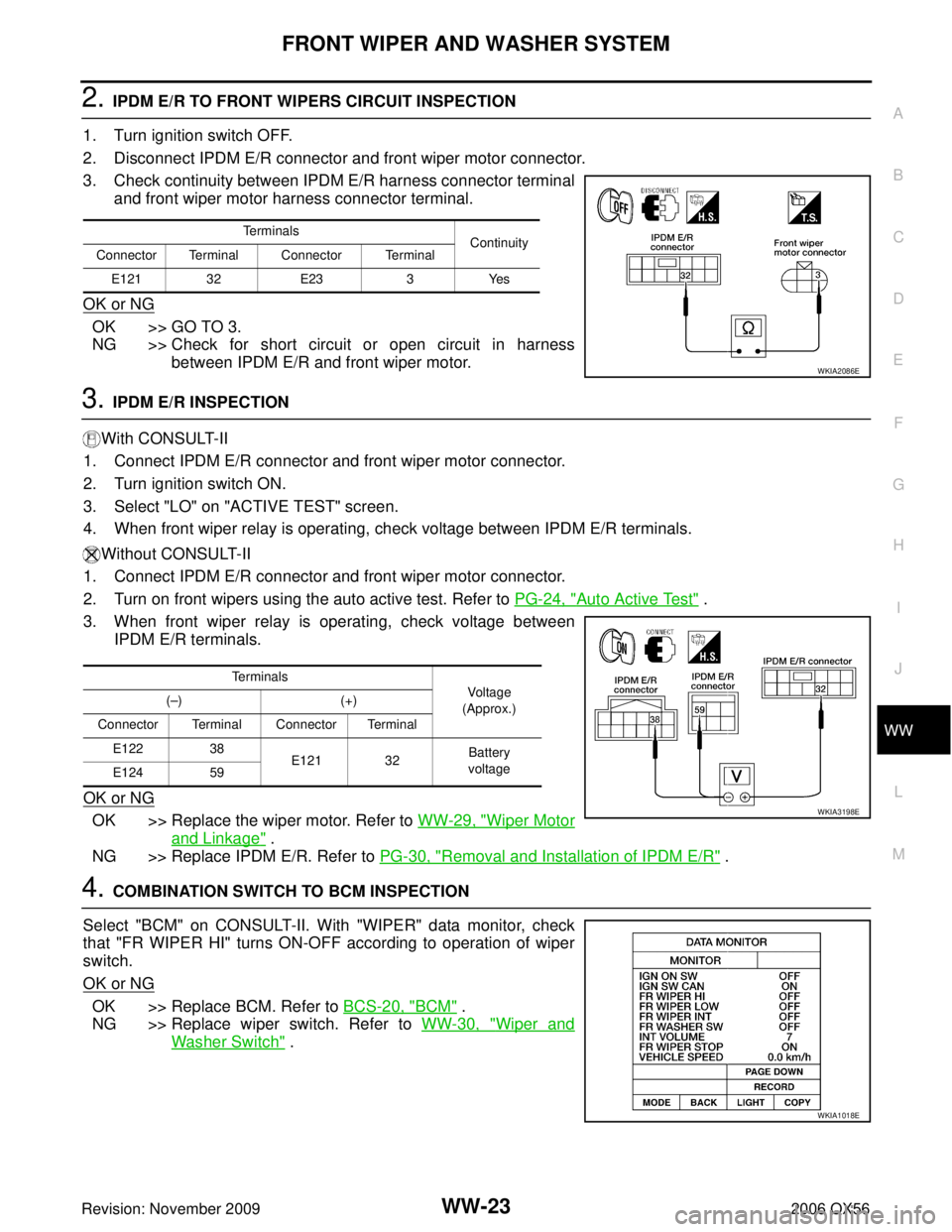
2. IPDM E/R TO FRONT WIPERS CIRCUIT INSPECTION
1. Turn ignition switch OFF.
2. Disconnect IPDM E/R connector and front wiper motor connector.
3. Check continuity between IPDM E/R harness connector terminal and front wiper motor harness connector terminal.
OK or NG
OK >> GO TO 3.
NG >> Check for short circuit or open circuit in harness between IPDM E/R and front wiper motor.
3. IPDM E/R INSPECTION
With CONSULT-II
1. Connect IPDM E/R connector and front wiper motor connector.
2. Turn ignition switch ON.
3. Select "LO" on "ACTIVE TEST" screen.
4. When front wiper relay is operating, check voltage between IPDM E/R terminals.
Without CONSULT-II
1. Connect IPDM E/R connector and front wiper motor connector.
2. Turn on front wipers using the auto active test. Refer to PG-24, "
Auto Active Test" .
3. When front wiper relay is operating, check voltage between IPDM E/R terminals.
OK or NG
OK >> Replace the wiper motor. Refer to WW-29, "Wiper Motor
and Linkage" .
NG >> Replace IPDM E/R. Refer to PG-30, "
Removal and Installation of IPDM E/R" .
4. COMBINATION SWITCH TO BCM INSPECTION
Select "BCM" on CONSULT-II. With "WIPER" data monitor, check
that "FR WIPER HI" turns ON-OFF according to operation of wiper
switch.
OK or NG
OK >> Replace BCM. Refer to BCS-20, "BCM" .
NG >> Replace wiper switch. Refer to WW-30, "
Wiper and
Washer Switch" .
Terminals Continuity
Connector Terminal Connector Terminal
E121 32 E233Yes
WKIA2086E
Terminals
Vo l ta g e
(Approx.)
(
– )( +)
Connector Terminal Connector Terminal E122 38
E121 32 Battery
voltage
E124 59
WKIA3198E
WKIA1018E
Page 3352 of 3383
FRONT WIPER AND WASHER SYSTEMWW-25
C
DE
F
G H
I
J
L
M A
B
WW
Revision: November 2009 2006 QX56
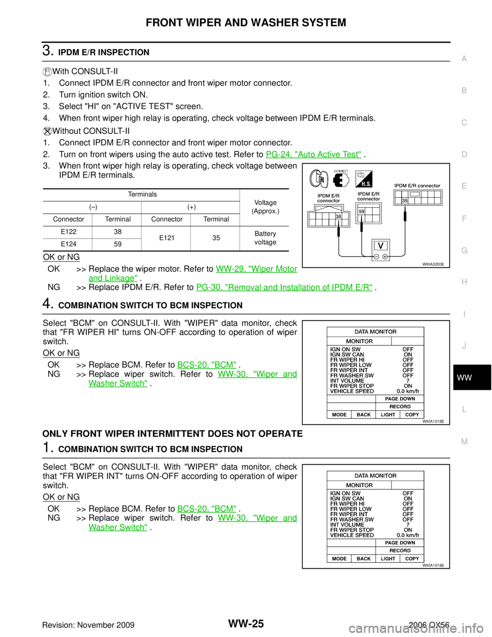
3. IPDM E/R INSPECTION
With CONSULT-II
1. Connect IPDM E/R connector and front wiper motor connector.
2. Turn ignition switch ON.
3. Select "HI" on "ACTIVE TEST" screen.
4. When front wiper high relay is operating, check voltage between IPDM E/R terminals.
Without CONSULT-II
1. Connect IPDM E/R connector and front wiper motor connector.
2. Turn on front wipers using the auto active test. Refer to PG-24, "
Auto Active Test" .
3. When front wiper high relay is operating, check voltage between IPDM E/R terminals.
OK or NG
OK >> Replace the wiper motor. Refer to WW-29, "Wiper Motor
and Linkage" .
NG >> Replace IPDM E/R. Refer to PG-30, "
Removal and Installation of IPDM E/R" .
4. COMBINATION SWITCH TO BCM INSPECTION
Select "BCM" on CONSULT-II. With "WIPER" data monitor, check
that "FR WIPER HI" turns ON-OFF according to operation of wiper
switch.
OK or NG
OK >> Replace BCM. Refer to BCS-20, "BCM" .
NG >> Replace wiper switch. Refer to WW-30, "
Wiper and
Washer Switch" .
ONLY FRONT WIPER INTERMITTENT DOES NOT OPERATE
1. COMBINATION SWITCH TO BCM INSPECTION
Select "BCM" on CONSULT-II. With "WIPER" data monitor, check
that "FR WIPER INT" turns ON-OFF according to operation of wiper
switch.
OK or NG
OK >> Replace BCM. Refer to BCS-20, "BCM" .
NG >> Replace wiper switch. Refer to WW-30, "
Wiper and
Washer Switch" .
Te r m i n a l s
Vo l ta g e
(Approx.)
(
– )(+)
Connector Terminal Connector Terminal E122 38
E121 35Battery
voltage
E124 59
WKIA3200E
WKIA1018E
WKIA1018E
Page 3354 of 3383
FRONT WIPER AND WASHER SYSTEMWW-27
C
DE
F
G H
I
J
L
M A
B
WW
Revision: November 2009 2006 QX56
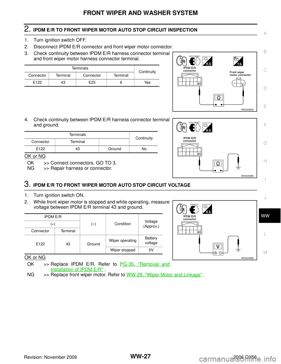
2. IPDM E/R TO FRONT WIPER MOTOR AUTO STOP CIRCUIT INSPECTION
1. Turn ignition switch OFF.
2. Disconnect IPDM E/R connector and front wiper motor connector.
3. Check continuity between IPDM E/R harness connector terminal and front wiper motor harness connector terminal.
4. Check continuity between IPDM E/R harness connector terminal and ground.
OK or NG
OK >> Connect connectors. GO TO 3.
NG >> Repair harness or connector.
3. IPDM E/R TO FRONT WIPER MOTOR AUTO STOP CIRCUIT VOLTAGE
1. Turn ignition switch ON.
2. While front wiper motor is stopped and while operating, measure voltage between IPDM E/R terminal 43 and ground.
OK or NG
OK >> Replace IPDM E/R. Refer to PG-30, "Removal and
Installation of IPDM E/R" .
NG >> Replace front wiper motor. Refer to WW-29, "
Wiper Motor and Linkage" .
Terminals
Continuity
Connector Terminal Connector Terminal
E122 43 E236Yes
WKIA2084E
Terminals
Continuity
Connector Terminal
E122 43Ground No
WKIA2088E
IPDM E/R
(– ) Condition Voltage
(Approx.)
(+)
Connector Terminal
E122 43 Ground Wiper operating
Battery
voltage
Wiper stopped 0V
WKIA2085E
Page 3365 of 3383
WW-38
REAR WIPER AND WASHER SYSTEM
Revision: November 20092006 QX56
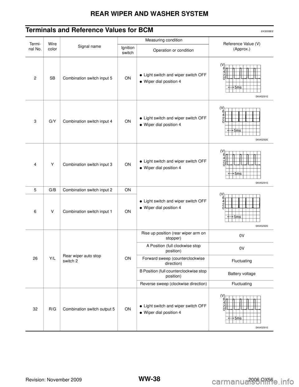
Terminals and Reference Values for BCMEKS00BEE
Te r m i -
nal No. Wire
color Signal name Measuring condition
Reference Value (V)
(Approx.)
Ignition
switch Operation or condition
2 SB Combination switch input 5 ON
�Light switch and wiper switch OFF
�Wiper dial position 4
3 G/Y Combination switch input 4 ON
�Light switch and wiper switch OFF
�Wiper dial position 4
4 Y Combination switch input 3 ON
�Light switch and wiper switch OFF
�Wiper dial position 4
5 G/B Combination switch input 2 ON
�Light switch and wiper switch OFF
�Wiper dial position 4
6 V Combination switch input 1 ON
26 Y/L Rear wiper auto stop
switch 2
ONRise up position (rear wiper arm on
stopper) 0V
A Position (full clockwise stop position) 0V
Forward sweep (counterclockwise direction) Fluctuating
B Position (full counterclockwise stop position) Battery voltage
Reverse sweep (clockwise direction) Fluctuating
32 R/G Combination switch output 5 ON
�Light switch and wiper switch OFF
�Wiper dial position 4
SKIA5291E
SKIA5292E
SKIA5291E
SKIA5292E
SKIA5291E
Page 3366 of 3383
REAR WIPER AND WASHER SYSTEMWW-39
C
DE
F
G H
I
J
L
M A
B
WW
Revision: November 2009 2006 QX56
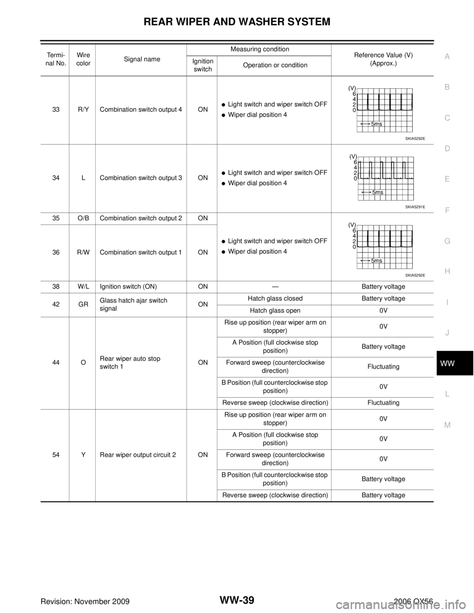
33 R/Y Combination switch output 4 ON�Light switch and wiper switch OFF
�Wiper dial position 4
34 L Combination switch output 3 ON
�Light switch and wiper switch OFF
�Wiper dial position 4
35 O/B Combination switch output 2 ON
�Light switch and wiper switch OFF
�Wiper dial position 4
36 R/W Combination switch output 1 ON
38 W/L Ignition switch (ON) ON— Battery voltage
42 GR Glass hatch ajar switch
signal ONHatch glass closed
Battery voltage
Hatch glass open 0V
44 O Rear wiper auto stop
switch 1 ONRise up position (rear wiper arm on
stopper) 0V
A Position (full clockwise stop position) Battery voltage
Forward sweep (counterclockwise direction) Fluctuating
B Position (full counterclockwise stop position) 0V
Reverse sweep (clockwise direction) Fluctuating
54 Y Rear wiper output circuit 2 ON Rise up position (rear wiper arm on
stopper) 0V
A Position (full clockwise stop position) 0V
Forward sweep (counterclockwise direction) 0V
B Position (full counterclockwise stop position) Battery voltage
Reverse sweep (clockwise direction) Battery voltage
Te r m i -
nal No. Wire
color Signal name Measuring condition
Reference Value (V)
(Approx.)
Ignition
switch Operation or condition
SKIA5292E
SKIA5291E
SKIA5292E
Page 3367 of 3383
WW-40
REAR WIPER AND WASHER SYSTEM
Revision: November 20092006 QX56
How to Proceed With Trouble DiagnosisEKS00BEF
1. Confirm the symptoms and customer complaint.
2. Understand operation description and function description. Refer to WW-32, "
System Description" .
3. Perform the Preliminary Check. Refer to WW-40, "
Preliminary Inspection" .
4. Check symptom and repair or replace the cause of malfunction.
5. Does the rear wiper operate normally? If YES: GO TO 6. If NO: GO TO 4.
6. Inspection End.
Preliminary InspectionEKS00BEG
INSPECTION FOR POWER SUPPLY AND GROUND CIRCUIT
Inspection procedure
1. CHECK FUSE
Check if wiper or washer fuse is blown.
OK or NG
OK >> GO TO 2.
NG >> If fuse is blown, be sure to eliminate cause of problem before installing new fuse. Refer to PG-4,
"POWER SUPPLY ROUTING CIRCUIT" .
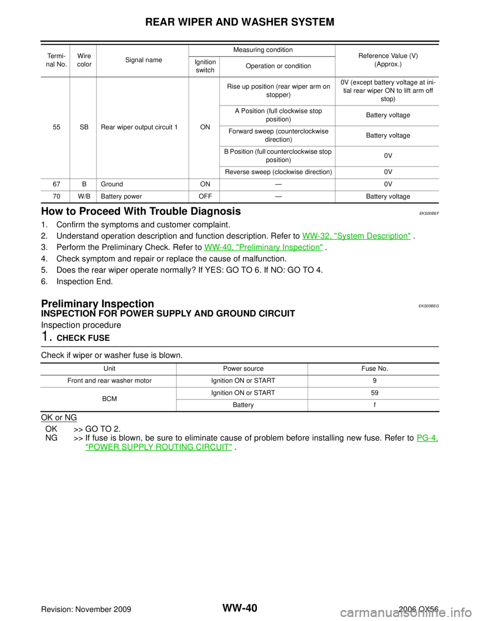
55 SB Rear wiper output circuit 1 ONRise up position (rear wiper arm on
stopper) 0V (except battery voltage at ini-
tial rear wiper ON to lift arm off
stop)
A Position (full clockwise stop position) Battery voltage
Forward sweep (counterclockwise direction) Battery voltage
B Position (full counterclockwise stop position) 0V
Reverse sweep (clockwise direction) 0V
67 B Ground ON— 0V
70 W/B Battery power OFF— Battery voltage
Te r m i -
nal No. Wire
color Signal name Measuring condition
Reference Value (V)
(Approx.)
Ignition
switch Operation or condition
Unit
Power source Fuse No.
Front and rear washer motor Ignition ON or START 9
BCM Ignition ON or START
59
Battery f
Page 3368 of 3383
REAR WIPER AND WASHER SYSTEMWW-41
C
DE
F
G H
I
J
L
M A
B
WW
Revision: November 2009 2006 QX56
2. CHECK POWER SUPPLY CIRCUIT
1. Disconnect BCM connectors.
2. Check voltage between BCM harness connector terminals and ground.
OK or NG
OK >> GO TO 3.
NG >> Check harness for open or short between BCM and fuse.
3. GROUND CIRCUIT INSPECTION (BCM)
Check for continuity between the BCM terminal and ground.
OK or NG
OK >> Inspection End.
NG >> Repair/replace BCM ground circuit.
Terminals Ignition switch position
(+) (– )O FF O N
Connector Terminal
M18 38 Ground0V
Battery voltage
M20 70 Battery voltage Battery voltage
WKIA2089E
Terminals
Ignition switch
condition Continuity
Connector Terminal
M20 67 Ground OFF Yes
WKIA2090E
Page 3374 of 3383
REAR WIPER AND WASHER SYSTEMWW-47
C
DE
F
G H
I
J
L
M A
B
WW
Revision: November 2009 2006 QX56
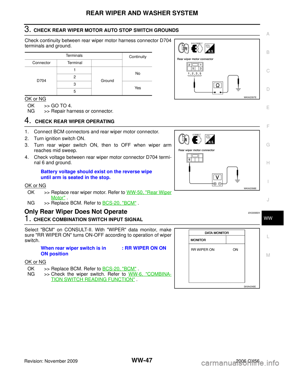
3. CHECK REAR WIPER MOTOR AUTO STOP SWITCH GROUNDS
Check continuity between rear wiper motor harness connector D704
terminals and ground.
OK or NG
OK >> GO TO 4.
NG >> Repair harness or connector.
4. CHECK REAR WIPER OPERATING
1. Connect BCM connectors and rear wiper motor connector.
2. Turn ignition switch ON.
3. Turn rear wiper switch ON, then to OFF when wiper arm reaches mid sweep.
4. Check voltage between rear wiper motor connector D704 termi- nal 6 and ground.
OK or NG
OK >> Replace rear wiper motor. Refer to WW-50, "Rear Wiper
Motor" .
NG >> Replace BCM. Refer to BCS-20, "
BCM" .
Only Rear Wiper Does Not OperateEKS00BEK
1. CHECK COMBINATION SWITCH INPUT SIGNAL
Select "BCM" on CONSULT-II. With "WIPER" data monitor, make
sure "RR WIPER ON" turns ON-OFF according to operation of wiper
switch.
OK or NG
OK >> Replace BCM. Refer to BCS-20, "BCM" .
NG >> Check the wiper switch. Refer to WW-6, "
COMBINA-
TION SWITCH READING FUNCTION" .
Terminals
Continuity
Connector Terminal
D704 1
Ground No
2
3
Ye s
5
WKIA2097E
Battery voltage should exist on the reverse wipe
until arm is seated in the stop.
WKIA2098E
When rear wiper switch is in
ON position : RR WIPER ON ON
SKIA4248E