Page 801 of 3383
BL-20
POWER DOOR LOCK SYSTEM
Revision: November 20092006 QX56
Wiring Diagram — D/LOCK —EIS005ZA
WIWA0742E
Page 831 of 3383
BL-50
REMOTE KEYLESS ENTRY SYSTEM
Revision: November 20092006 QX56
Wiring Diagram — KEYLES —EIS005ZT
WIWA1308E
Page 847 of 3383

BL-66
REMOTE KEYLESS ENTRY SYSTEM
Revision: November 20092006 QX56
2. CHECK KEYFOB FUNCTION
With CONSULT-II
Check keyfob function in “DATA MONITOR” mode with CONSULT-II.
When pushing each button of keyfob, the corresponding monitor item should
be turned as follows.
Without CONSULT-II
Check keyfob function using Remote Keyless Entry Tester J-43241.
OK or NG
OK >> WITH CONSULT-II: Keyfob, remote keyless entry receiver and wiring harness between BCM and remote keyless entry receiver are OK. Replace BCM. Refer to BCS-20, "
BCM" .
OK >> WITHOUT CONSULT-II: Keyfob is OK. Further inspection is necessary. Refer to BL-60, "
SYMP-
TOM CHART" .
NG >> WITH CONSULT-II: Further inspection is necessary. Refer to BL-60, "
SYMPTOM CHART" .
NG >> WITHOUT CONSULT-II: Replace keyfob. Refer to BL-71, "
ID Code Entry Procedure" .
Remote Keyless Entry Receiver System CheckEIS00605
1. REMOTE KEYLESS ENTRY RECEIVER SIGNAL
Check signal voltage waveform between BCM connector M18 termi-
nal 20 and ground using an oscilloscope.
OK or NG
OK >> Remote keyless entry receiver signal power supply, ground and signal circuits are OK. Replace BCM. Refer to BCS-20, "
BCM" .
NG >> GO TO 2. Condition
Monitor item
Pushing LOCK KEYLESS LOCK : ON
Pushing UNLOCK KEYLESS UNLOCK : ON
Keep pushing UNLOCK RKE KEEP UNLK
turns to ON 3 seconds
after UNLOCK button
is pushed.
Pushing PANIC KEYLESS PANIC : ON
Pushing LOCK and UNLOCK
at the same time RKE LCK-UNLCK : ON
Pushing Power Back Door KEYLESS PBD : ON
LIIA1487E
Condition:
Keyfob buttons released : Refer to BL-53, "
Te r m i -
nals and Reference Value
for BCM" .
Keyfob buttons pressed : Refer to BL-53, "
Te r m i -
nals and Reference Value
for BCM" .LIIA1275E
Page 861 of 3383
BL-80
VEHICLE SECURITY (THEFT WARNING) SYSTEM
Revision: November 20092006 QX56
Wiring Diagram — VEHSEC —EIS0060I
WIWA1227E
Page 887 of 3383
BL-106
AUTOMATIC BACK DOOR SYSTEM
Revision: November 20092006 QX56
Wiring Diagram — B/CLOS —EIS0060Z
WIWA2211E
Page 921 of 3383
BL-140
IVIS (INFINITI VEHICLE IMMOBILIZER SYSTEM-NATS)
Revision: November 20092006 QX56
Wiring Diagram — NATS —EIS0061K
WIWA1548E
Page 937 of 3383
BL-156
HOMELINK UNIVERSAL TRANSCEIVER
Revision: November 20092006 QX56
HOMELINK UNIVERSAL TRANSCEIVERPFP:96401
Wiring Diagram — TRNSCV —EIS0061W
WIWA0759E
Page 996 of 3383

PRECAUTIONSBR-3
C
DE
G H
I
J
K L
M A
B
BR
Revision: November 2009 2006 QX56
PRECAUTIONSPFP:00001
Precautions for Supplemental Restraint System (SRS) “AIR BAG” and “SEAT
BELT PRE-TENSIONER”
EFS004VW
The Supplemental Restraint System such as “AIR BAG” and “SEAT BELT PRE-TENSIONER ”, used along
with a front seat belt, helps to reduce the risk or severity of injury to the driver and front passenger for certain
types of collision. This system includes seat belt switch inputs and dual stage front air bag modules. The SRS
system uses the seat belt switches to determine the front air bag deployment, and may only deploy one front
air bag, depending on the severity of a collision and whether the front occupants are belted or unbelted.
Information necessary to service the system safely is included in the SRS and SB section of this Service Man-
ual.
WARNING:
�To avoid rendering the SRS inoperative, which could increase the risk of personal injury or death
in the event of a collision which would result in air bag inflation, all maintenance must be per-
formed by an authorized NISSAN/INFINITI dealer.
�Improper maintenance, including incorrect removal and installation of the SRS, can lead to per-
sonal injury caused by unintentional activation of the system. For removal of Spiral Cable and Air
Bag Module, see the SRS section.
�Do not use electrical test equipment on any circuit related to the SRS unless instructed to in this
Service Manual. SRS wiring harnesses can be identified by yellow and/or orange harnesses or
harness connectors.
Precautions for Brake SystemEFS004VX
�Always use recommended brake fluid. Refer to MA-11, "RECOMMENDED FLUIDS AND LUBRICANTS" .
�Do not reuse drained brake fluid.
�Be careful not to splash brake fluid on painted areas.
�To clean or wash all parts of master cylinder, disc brake caliper and wheel cylinder, use clean brake fluid.
�Do not use mineral oils such as gasoline or kerosene. They will ruin rubber parts of the hydraulic system.
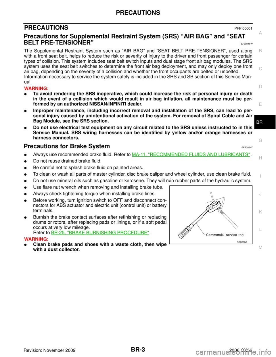
�Use flare nut wrench when removing and installing brake tube.
�Always check tightening torque when installing brake lines.
�Before working, turn ignition switch to OFF and disconnect con-
nectors for ABS actuator and electric unit (control unit) or battery
terminals.
�Burnish the brake contact surfaces after refinishing or replacing
drums or rotors, after replacing pads or linings, or if a soft pedal
occurs at very low mileage.
Refer to BR-25, "
BRAKE BURNISHING PROCEDURE" .
WARNING:
�Clean brake pads and shoes with a waste cloth, then wipe
with a dust collector.SBR686C