Page 2869 of 3383
RSU-30
REAR SUSPENSION ASSEMBLY
Revision: November 20092006 QX56
5. Push the vehicle slowly ahead to rotate the wheels 180° (a half
turn).
If the wheels are rotated more than 180 ° (a half turn), then
repeat the above steps. Never push the vehicle backward.
6. Measure the distance “B” (front side) across from tire to tire.
7. If the toe-in is outside the specified value, adjust the toe-in using the adjusting bolt in the rear lower link.
CAUTION:
Be sure to adjust equally on RH and LH sides using the
adjusting bolt.
NOTE:
Toe changes about 1.5 mm (0.059 in) [one side] with each grad-
uation of the adjusting bolt.
8. Tighten the adjusting bolt nuts to specification. Total toe-in : Refer to
RSU-48, "
Wheel Alignment" .
SFA234AC
LEIA0009E
Page 2870 of 3383
REAR SUSPENSION MEMBERRSU-31
C
DF
G H
I
J
K L
M A
B
RSU
Revision: November 2009 2006 QX56
REAR SUSPENSION MEMBERPFP:55501
Removal and InstallationEES001HI
Rear Suspension
WEIA0092E
Page 2871 of 3383

RSU-32
REAR SUSPENSION MEMBER
Revision: November 20092006 QX56
Rear Load Leveling Air Suspension System
REMOVAL
1. Use the CONSULT-II “EXHAUST SOLENOID” active test to release the air pressure from the rear load
leveling air suspension system.
2. Disconnect the electrical connectors for the height sensor and the rear load leveling air suspension com- pressor assembly.
3. Unclip the rubber cover to access the rear load leveling air suspension compressor assembly.
1. Seat belt latch anchor 2. Stabilizer bar bushing 3. Stabilizer bar clamp
4. Stabilizer bar 5. Connecting rod 6. Front lower link
7. Knuckle 8. Bushing 9. Rear lower link
10. Shock absorber 11. Suspension arm 12. Lower rubber seat
13. Coil spring 14. Upper rubber seat 15. Rear suspension member
16. Spare tire bracket 17. Bound bumper
LEIA0072E
1. Rear load leveling air suspension
hose, RH 2. Shock absorber, RH 3. Height sensor
4. Rear load leveling air suspension hose, LH 5. Shock absorber, LH
6. Rear load leveling air suspension
compressor assembly (includes the
bracket and rubber cover)
Page 2872 of 3383

REAR SUSPENSION MEMBERRSU-33
C
DF
G H
I
J
K L
M A
B
RSU
Revision: November 2009 2006 QX56
4. Disconnect the rear load leveling air suspension hoses at the
rear load leveling air suspension compressor assembly.
�To disconnect the hoses, push in on the lock ring using a suit-
able tool and pull the hose out.
5. Remove both of the rear wheel and tire assemblies using power tool.
6. Remove the brake caliper without disconnecting the brake hoses, using power tool. Reposition the brake caliper out of the
way using a suitable wire. Refer to BR-28, "
Removal and Instal-
lation of Brake Caliper and Disc Rotor" .
CAUTION:
�Do not crimp or stretch the brake hose when repositioning the brake caliper out of the way.
�Do not press brake pedal while the brake caliper is removed.
7. Remove the spare tire.
8. Disconnect the two rear ABS sensor electrical connectors.
9. Remove the two rear drive shafts. Refer to RAX-7, "
Removal and Installation" .
10. Remove the rear final drive. Refer to RFD-13, "
REAR FINAL DRIVE ASSEMBLY" .
11. Remove the EVAP canister bolt from the top of the rear suspension member.
12. Disconnect the parking brake cables from the brackets on the rear suspension member.
13. Set a suitable jack to support each of the rear lower links and the coil spring tension.
14. Remove both of the rear lower link outer bolts and lower the jack to remove the rear coil springs.
15. Remove the two bolts to disconnect the seat belt latch anchor from the rear suspension member.
16. Disconnect both of the connecting rods from the rear stabilizer bar.
17. Set a suitable jack under the rear suspension member.
18. Remove the six rear suspension member bolts.
19. Slowly lower the jack to remove the rear suspension member, suspension arm, front and rear lower links and stabilizer bar as
an assembly.
20. If necessary, remove the suspension arm, spare tire bracket, height sensor, rear load leveling air suspension hoses, stabilizer
bar, knuckle, and front and rear lower links from the rear suspension member.
INSPECTION AFTER REMOVAL
Check the rear suspension member for deformation, cracks, and other damage and replace if necessary.
LEIA0074E
LEIA0077E
LEIA0075E
Page 2873 of 3383

RSU-34
REAR SUSPENSION MEMBER
Revision: November 20092006 QX56
INSTALLATION
Installation is in the reverse order of removal.
�When raising the rear suspension member assembly, use the
locating pins to align the rear suspension member to the vehicle
body.
�When installing the upper and lower rubber seats for the rear
coil springs, the arrow embossed on the rubber seats must point
out toward the wheel and tire assembly.
�To connect the rear load leveling air suspension hoses, the lock
ring must be fully seated in the fitting. Insert the hose “B” into the
lock ring “A” until the lock ring “A” is touching the hose “B” as
shown. Pull on the hose to check that it is securely inserted.
�Perform the final tightening of the nuts and bolts for the links (rubber bushing) under unladen condition
(unladen condition means that the fuel tank, engine coolant and lubricants are at the full specification, and
the spare tire, jack, hand tools, and mats are in their designated positions) with the tires on level ground.
�Check the wheel alignment. Refer to RSU-48, "Wheel Alignment" .
LEIA0083E
LEIA0076E
LEIA0078E
Page 2874 of 3383

SHOCK ABSORBERRSU-35
C
DF
G H
I
J
K L
M A
B
RSU
Revision: November 2009 2006 QX56
SHOCK ABSORBERPFP:56210
Removal and Installation EES001HJ
REMOVAL
1. Remove the wheel and tire assembly using power tool. Refer to WT-7, "Rotation" .
2. Use CONSULT-II “EXHAUST SOLENOID ” active test to release the air pressure from the rear load level-
ing air suspension system.
3. Remove the four clips and remove the rear fender protector, front.
4. Disconnect the rear load leveling air suspension hose from the shock absorber.
�To disconnect the hose, push in on the lock ring using a suit-
able tool and pull the air hose out.
5. Remove the shock absorber upper and lower end bolts using power tool.
6. Remove the shock absorber.
CAUTION:
Do not damage the rubber boot on the shock absorber.
INSTALLATION
Installation is in the reverse order of removal.
�Tighten the shock absorber bolts to specification. Refer to RSU-26, "Components" .
INSPECTION AFTER INSTALLATION
�Check the shock absorber for any air leaks or damage to the rubber boot.
�Check the shock absorber for smooth operation through a full stroke, both compression and extension.
�Check piston rod for cracks, deformation or other damage and replace if necessary.
LEIA0081E
LEIA0082E
Page 2875 of 3383

RSU-36
SUSPENSION ARM
Revision: November 20092006 QX56
SUSPENSION ARMPFP:55501
Removal and Installation EES001HK
REMOVAL
1. Remove the rear suspension member assembly using power tool. Refer to RSU-31, "Removal and Instal-
lation" .
NOTE:
It is necessary to remove the rear suspension member to remove the front upper bolt from the suspension
arm.
2. Remove the shock absorber upper end bolt.
3. Remove the suspension arm upper nuts and bolts on the sus- pension member side using power tool.
4. Remove the suspension arm pinch bolt and nut on the knuckle side using power tool.
5. Disconnect the suspension arm from the knuckle using a soft hammer.
CAUTION:
Do not damage the ball joint with the soft hammer.
6. Remove the suspension arm.
INSPECTION AFTER REMOVAL
�Check the suspension arm for damage, cracks, deformation and replace if necessary.
�Check the rubber bushing for damage, cracks and deformation. Replace suspension arm assembly if nec-
essary.
�Before checking, turn the ball joint at least 10 revolutions so that the ball joint is properly broken in.
LEIA0082E
LEIA0087E
Page 2876 of 3383
SUSPENSION ARMRSU-37
C
DF
G H
I
J
K L
M A
B
RSU
Revision: November 2009 2006 QX56
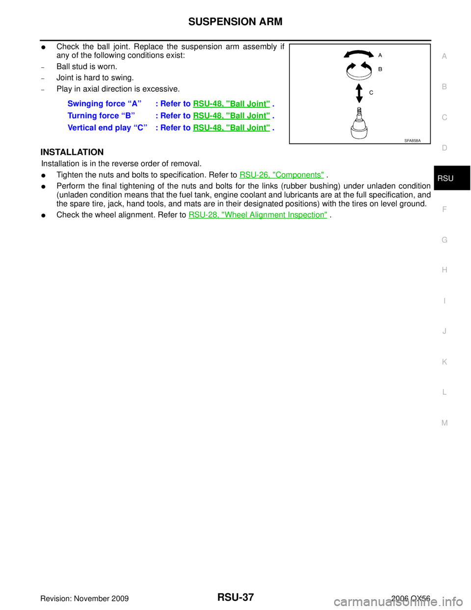
�Check the ball joint. Replace the suspension arm assembly if
any of the following conditions exist:
–Ball stud is worn.
–Joint is hard to swing.
–Play in axial direction is excessive.
INSTALLATION
Installation is in the reverse order of removal.
�Tighten the nuts and bolts to specification. Refer to RSU-26, "Components" .
�Perform the final tightening of the nuts and bolts for the links (rubber bushing) under unladen condition
(unladen condition means that the fuel tank, engine coolant and lubricants are at the full specification, and
the spare tire, jack, hand tools, and mats are in their designated positions) with the tires on level ground.
�Check the wheel alignment. Refer to RSU-28, "Wheel Alignment Inspection" .
Swinging force “A” : Refer to
RSU-48, "
Ball Joint" .
Turning force “B” : Refer to RSU-48, "
Ball Joint" .
Vertical end play “C” : Refer to RSU-48, "
Ball Joint" .
SFA858A
.
If the wheels are rotated more than 180 ° (a half turn), th")