Page 2265 of 3383
IP-16
INSTRUMENT PANEL ASSEMBLY
Revision: November 20092006 QX56
Center ConsoleEIS007XB
REMOVAL AND INSTALLATION
WIIA0923E
Page 2266 of 3383

INSTRUMENT PANEL ASSEMBLYIP-17
C
DE
F
G H
J
K L
M A
B
IP
Revision: November 2009 2006 QX56
Removal
1. Move front seats forward.
2. Disconnect battery negative terminal.
3. Remove control device. Refer to AT- 2 2 6 , "
Control Device Removal and Installation" .
4. Remove glove box assembly. Refer to IP-14, "
Lower Instrument Panel RH and Glove Box" .
5. Remove center console lower cover RH.
6. Remove console cover RH screws.
7. Remove center console lower cover LH.
8. Remove console cover LH screws.
9. Disconnect center console electrical connectors.
10. Remove center console assembly in a rearward direction.
Installation
Installation is in the reverse order of removal.
Center ConsoleEIS007X7
DISASSEMBLY AND ASSEMBLY
Disassembly
1. Remove mats from storage compartment and console bin.
2. Remove latch from console lid and remove key cylinder from latch.
3. Remove console lid.
4. Remove console bin.
5. Disconnect electrical harness from DVD player (if equipped).
6. Remove hinge.
7. Remove rear upper finisher.
8. Remove rear cup holder assembly.
9. Remove rear finisher assembly.
10. Disconnect rear finisher assembly electrical connectors.
11. Remove console power socket.
12. Remove upper side finishers LH/RH.
13. Remove heat duct and console rear duct.
14. Disconnect clips and remove console covers LH/RH.
15. Remove mask and storage compartment.
16. Remove console front bracket.
17. Remove console rear bracket.
ASSEMBLY
Assembly is in the reverse order of disassembly.
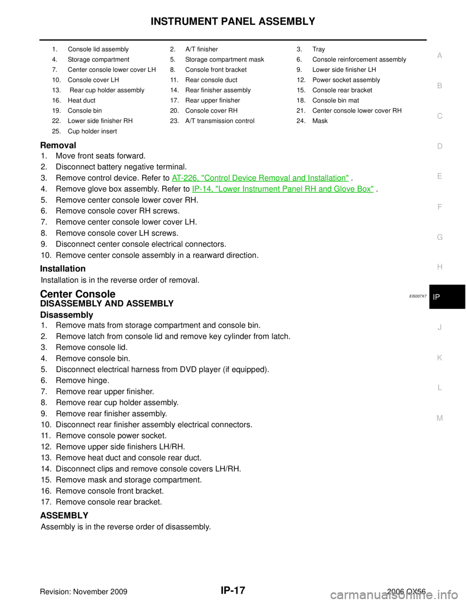
1. Console lid assembly 2. A/T finisher 3. Tray
4. Storage compartment 5. Storage compartment mask 6. Console reinforcement assembly
7. Center console lower cover LH 8. Console front bracket 9. Lower side finisher LH
10. Console cover LH 11. Rear console duct 12. Power socket assembly
13. Rear cup holder assembly 14. Rear finisher assembly 15. Console rear bracket
16. Heat duct 17. Rear upper finisher 18. Console bin mat
19. Console bin 20. Console cover RH 21. Center console lower cover RH
22. Lower side finisher RH 23. A/T transmission control 24. Mask
25. Cup holder insert
Page 2267 of 3383
IP-18
INSTRUMENT PANEL ASSEMBLY
Revision: November 20092006 QX56
Rear ConsoleEIS007XC
REMOVAL AND INSTALLATION
1. Lid assembly2. Lid latch 3. Console bin
4. Cup holder insert 5. Rear upper console assembly 6. Rubber bumper
7. Floor latch 8. Rear console floor bracket 9. Rear console floor base
10. Hinge cover 11. Hinge 12. Base hook
13. Rear lower console assembly 14. Console bin mat
LIIA0938E
Page 2268 of 3383
INSTRUMENT PANEL ASSEMBLYIP-19
C
DE
F
G H
J
K L
M A
B
IP
Revision: November 2009 2006 QX56
Removal
1. Remove cup holder insert.
2. Release latch and remove rear console assembly.
Installation
Installation is in the reverse order of removal.
Rear ConsoleEIS007XD
DISASSEMBLY AND ASSEMBLY
Disassembly
1. Remove hinge cover.
2. Remove screws and remove lid assembly.
3. Remove screw and remove latch from lid assembly
4. Remove screws and remove hinge.
5. Remove screws and separate rear upper console assembly and rear lower console assembly.
6. Remove floor latch from rear upper console assembly.
7. Remove screws and remove console bin from rear upper console assembly.
8. Remove screws and remove rear console floor base.
9. Remove bolts and remove rear console floor bracket.
Assembly
Assembly is in the reverse order of disassembly.
Page 2269 of 3383
IP-20
INSTRUMENT PANEL ASSEMBLY
Revision: November 20092006 QX56
Page 2471 of 3383
LT-64
AUTO LIGHT SYSTEM
Revision: November 20092006 QX56
Optical SensorEKS00B96
REMOVAL AND INSTALLATION
Removal
1. Remove defrost grille. Refer to IP-10, "INSTRUMENT PANEL ASSEMBLY" .
2. Disconnect the connector.
3. Turn the optical sensor counterclockwise to remove it from defroster grille.
Installation
Installation is in the reverse order of removal.
WKIA1061E
Page 2475 of 3383
LT-68
HEADLAMP AIMING CONTROL
Revision: November 20092006 QX56
Headlamp Aiming SwitchEKS00B99
REMOVAL AND INSTALLATION
Removal
1. Remove cluster lid A. Refer to IP-10, "INSTRUMENT PANEL ASSEMBLY" .
2. Carefully release the headlamp aiming switch retaining pawls and remove the switch.
Installation
Installation is in the reverse order of removal.
Switch Circuit InspectionEKS00B9A
Using a circuit tester, check continuity between the headlamp aiming
switch connector terminals in each operation status of the aiming
switch.
WKIA1879E
Resistor tolerance : ± 5%
WKIA1882E
Page 2533 of 3383

LT-126
TRAILER TOW
Revision: November 20092006 QX56
TRAILER TOWPFP:93020
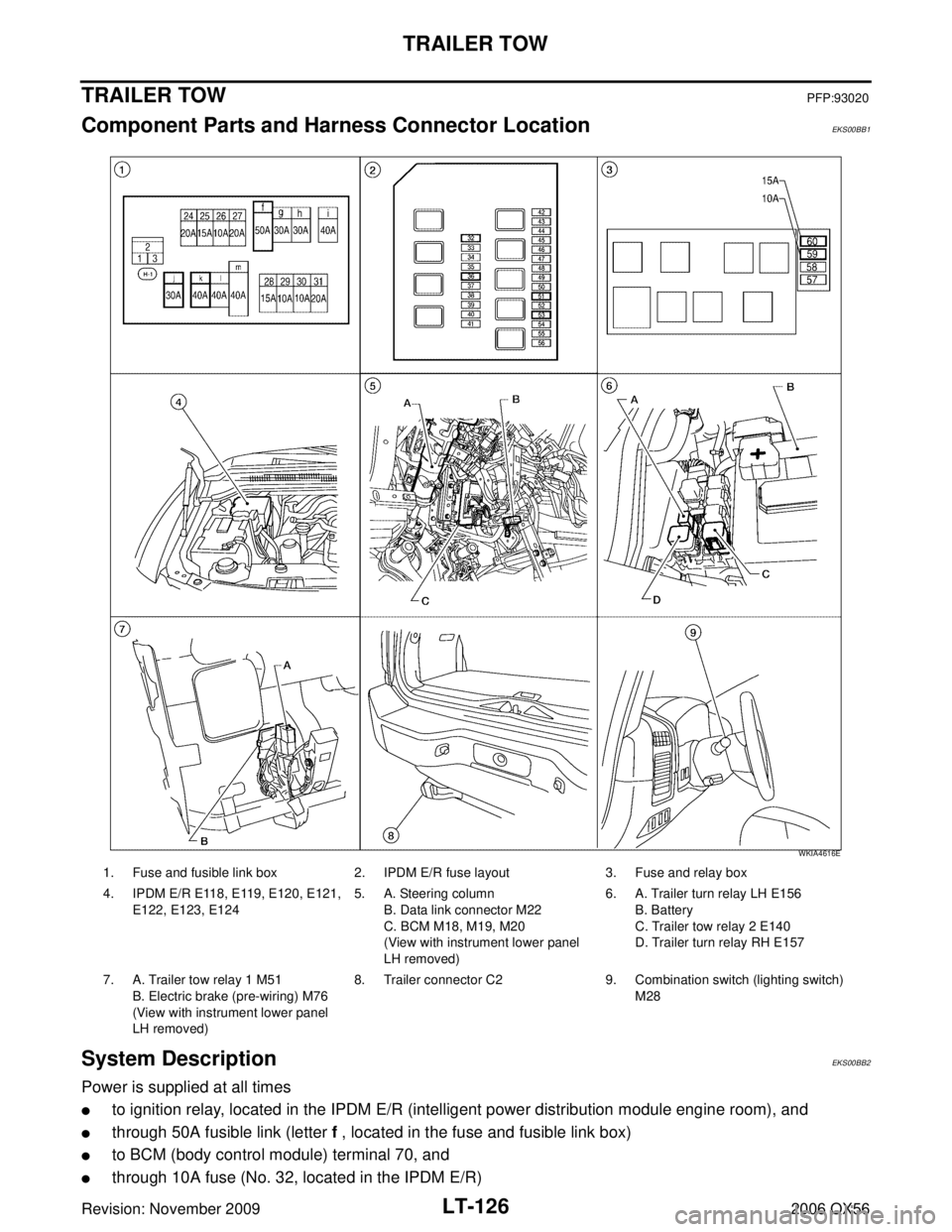
Component Parts and Harness Connector LocationEKS00BB1
System DescriptionEKS00BB2
Power is supplied at all times
�to ignition relay, located in the IPDM E/R (intelligent power distribution module engine room), and
�through 50A fusible link (letter f , located in the fuse and fusible link box)
�to BCM (body control module) terminal 70, and
�through 10A fuse (No. 32, located in the IPDM E/R)
1. Fuse and fusible link box2. IPDM E/R fuse layout 3. Fuse and relay box
4. IPDM E/R E118, E119, E120, E121, E122, E123, E124 5. A. Steering column
B. Data link connector M22
C. BCM M18, M19, M20
(View with instrument lower panel
LH removed) 6. A. Trailer turn relay LH E156
B. Battery
C. Trailer tow relay 2 E140
D. Trailer turn relay RH E157
7. A. Trailer tow relay 1 M51 B. Electric brake (pre-wiring) M76
(View with instrument lower panel
LH removed) 8. Trailer connector C2
9. Combination switch (lighting switch)
M28
WKIA4616E