Page 2927 of 3383
SC-22
CHARGING SYSTEM
Revision: November 20092006 QX56
DIAGNOSTIC PROCEDURE 1
Check Charge Warning Lamp Circuit
1. CHECK CHARGE WARNING LAMP CIRCUIT CONNECTION
1. Turn the ignition switch OFF.
2. Check to see if terminal 3 is clean and tight.
OK or NG
OK >> GO TO 2.
NG >> Repair terminal 3 connection. Confirm repair by performing complete Battery/Starting/Charging system test.
2. CHECK CHARGE WARNING LAMP CIRCUIT
1. Disconnect E205 connector from generator.
2. Apply ground to connector E205 terminal 3 with the ignition switch in the ON position.
OK or NG
OK >> GO TO SC-21, "WORK FLOW" .
NG >> Check the following.
�10A fuse [No. 14, located in fuse block (J/B)]
�Charge warning lamp
�Harness for open or short between combination
meter and fuse
�Harness for open or short between combination meter and generator
Charge warning lamp should
light up.
WKIA2110E
Page 3079 of 3383
SRS-38
TROUBLE DIAGNOSIS
Revision: November 20092006 QX56
Trouble Diagnosis Without CONSULT-IIEHS001MZ
DIAGNOSTIC PROCEDURE 6
Inspect SRS Malfunction Using "AIR BAG" Warning Lamp—Diagnosis Mode
NOTE:
SRS will not enter Diagnosis mode if no malfunction is detected in User mode.
1. Turn ignition switch ON.
2. After “AIR BAG ” warning lamp lights for 7 seconds, turn ignition switch OFF within 1 second.
3. Wait more than 3 seconds.
4. Repeat steps 1 to 3 two more times (3 times total).
5. Turn ignition switch ON.
SRS is now in Diagnosis mode.
"AIR BAG" warning lamp operates in Diagnosis mode as follows:
Page 3140 of 3383

TROUBLE DIAGNOSISTF-35
CE F
G H
I
J
K L
M A
B
TF
Revision: November 2009 2006 QX56
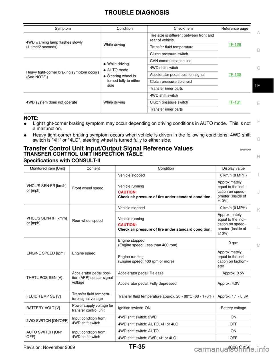
NOTE:
�Light tight-corner braking symptom may occur depending on driving conditions in AUTO mode. This is not
a malfunction.
�Heavy tight-corner braking symptom occurs when vehicle is driven in the following conditions: 4WD shift
switch is "4H" or "4LO", steering wheel is turned fully to either side.
Transfer Control Unit Input/Output Signal Reference ValuesEDS002HJ
TRANSFER CONTROL UNIT INSPECTION TABLE
Specifications with CONSULT-II
4WD warning lamp flashes slowly
(1 time/2 seconds)While drivingTire size is different between front and
rear of vehicle.
TF-129
Transfer fluid temperature
Clutch pressure switch
Heavy tight-corner braking symptom occurs
(See NOTE.)
�While driving
�AUTO mode
�Steering wheel is
turned fully to either
side CAN communication line
TF-130
4WD shift switch
Accelerator pedal position signal
Clutch pressure solenoid
Transfer inner parts
4WD system does not operate While driving 4WD shift switch
TF-131
Clutch pressure switch
Transfer inner parts
Symptom
ConditionCheck itemReference page
Monitored item [Unit] Content ConditionDisplay value
VHCL/S SEN ·FR [km/h]
or [mph] Front wheel speed Vehicle stopped
0 km/h (0 MPH)
Vehicle running
CAUTION:
Check air pressure of tire under standard condition. Approximately
equal to the indi-
cation on speed-
ometer (Inside of
±
10%)
VHCL/S SEN ·RR [km/h]
or [mph] Rear wheel speed Vehicle stopped
0 km/h (0 MPH)
Vehicle running
CAUTION:
Check air pressure of tire under standard condition. Approximately
equal to the indi-
cation on speed-
ometer (Inside of
±
10%)
ENGINE SPEED [rpm] Engine speed Engine stopped
(Engine speed: Less than 400 rpm)
0 rpm
Engine running
(Engine speed: 400 rpm or more) Approximately
equal to the indi-
cation on tachom-
eter
THRTL POS SEN [V] Accelerator pedal posi-
tion (APP) sensor signal
voltage Accelerator pedal: Release
Approx. 0.5V
Accelerator pedal: Fully depressed Approx. 4.0V
FLUID TEMP SE [V] Transfer fluid tempera-
ture signal voltage Transfer fluid temperature approx. 20 - 80°C (68 - 176
°F) Approx. 1.1 - 0.3V
BATTERY VOLT [V] Power supply voltage for
transfer control unit
Ignition switch: ON
Battery voltage
2WD SWITCH [ON/OFF] Input condition from
4WD shift switch 4WD shift switch: 2WD
ON
4WD shift switch: AUTO, 4H or 4LO OFF
AUTO SWITCH [ON/
OFF] Input condition from
4WD shift switch 4WD shift switch: AUTO
ON
4WD shift switch: 2WD, 4H or 4LO OFF