Page 2868 of 3383

REAR SUSPENSION ASSEMBLYRSU-29
C
DF
G H
I
J
K L
M A
B
RSU
Revision: November 2009 2006 QX56
�Check with the manufacturer of your specific alignment machine for their recommended Service/Cali-
bration Schedule.
THE ALIGNMENT PROCESS
IMPORTANT: Use only the alignment specifications listed in this Service Manual. Refer to RSU-48, "Wheel
Alignment" .
1. When displaying the alignment settings, many alignment machines use “indicators”: (Green/red, plus or
minus, Go/No Go). Do NOT use these indicators.
�The alignment specifications programmed into your alignment machine that operate these indicators
may not be correct.
�This may result in an ERROR.
2. Some newer alignment machines are equipped with an optional “Rolling Compensation” method to “com-
pensate ” the sensors (alignment targets or head units). Do NOT use this “Rolling Compensation”
method.
�Use the “Jacking Compensation ” method. After installing the alignment targets or head units, raise the
vehicle and rotate the wheels 1/2 turn both ways.
�See Instructions in the alignment machine you are using for more information.
CAMBER
1. Measure camber of both the right and left wheels with a suitable alignment gauge and adjust as necessary to specification.
2. If outside of the specified value, adjust the camber using the adjusting bolt in the front lower link.
CAUTION:
After adjusting the camber then check the toe-in.
NOTE:
Camber changes about 0 ° 5' with each graduation of the adjust-
ing bolt.
3. Tighten the adjusting bolt nuts to specification.
TOE-IN
1. Bounce the rear of the vehicle up and down two to three times to stabilize the vehicle height. Refer to RSU-49, "
Wheelarch Height (Unladen*1 )" .
2. Push the vehicle straight ahead about 5 m (16 ft).
3. Put a mark on the base line of the tread (rear side) of both of the tires at the same height as the center of the hub. This will be the
measuring points.
4. Measure the distance “A” (rear side) across from tire to tire.
Camber : Refer to
RSU-48, "
Wheel Alignment" .
SRA096A
LEIA0041E
SFA614B
Page 2869 of 3383
RSU-30
REAR SUSPENSION ASSEMBLY
Revision: November 20092006 QX56
5. Push the vehicle slowly ahead to rotate the wheels 180° (a half
turn).
If the wheels are rotated more than 180 ° (a half turn), then
repeat the above steps. Never push the vehicle backward.
6. Measure the distance “B” (front side) across from tire to tire.
7. If the toe-in is outside the specified value, adjust the toe-in using the adjusting bolt in the rear lower link.
CAUTION:
Be sure to adjust equally on RH and LH sides using the
adjusting bolt.
NOTE:
Toe changes about 1.5 mm (0.059 in) [one side] with each grad-
uation of the adjusting bolt.
8. Tighten the adjusting bolt nuts to specification. Total toe-in : Refer to
RSU-48, "
Wheel Alignment" .
SFA234AC
LEIA0009E
Page 2873 of 3383

RSU-34
REAR SUSPENSION MEMBER
Revision: November 20092006 QX56
INSTALLATION
Installation is in the reverse order of removal.
�When raising the rear suspension member assembly, use the
locating pins to align the rear suspension member to the vehicle
body.
�When installing the upper and lower rubber seats for the rear
coil springs, the arrow embossed on the rubber seats must point
out toward the wheel and tire assembly.
�To connect the rear load leveling air suspension hoses, the lock
ring must be fully seated in the fitting. Insert the hose “B” into the
lock ring “A” until the lock ring “A” is touching the hose “B” as
shown. Pull on the hose to check that it is securely inserted.
�Perform the final tightening of the nuts and bolts for the links (rubber bushing) under unladen condition
(unladen condition means that the fuel tank, engine coolant and lubricants are at the full specification, and
the spare tire, jack, hand tools, and mats are in their designated positions) with the tires on level ground.
�Check the wheel alignment. Refer to RSU-48, "Wheel Alignment" .
LEIA0083E
LEIA0076E
LEIA0078E
Page 2876 of 3383
SUSPENSION ARMRSU-37
C
DF
G H
I
J
K L
M A
B
RSU
Revision: November 2009 2006 QX56
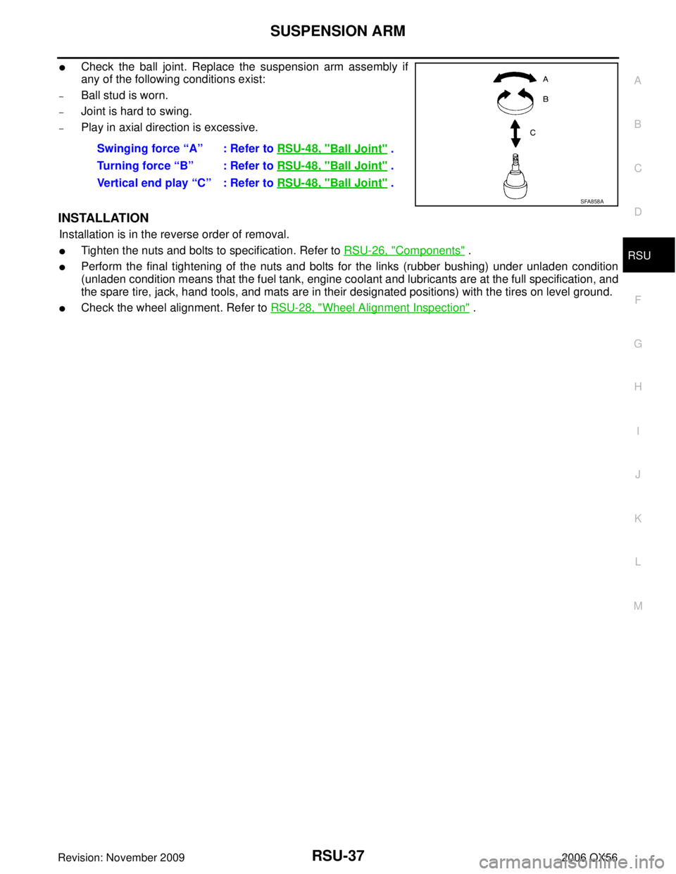
�Check the ball joint. Replace the suspension arm assembly if
any of the following conditions exist:
–Ball stud is worn.
–Joint is hard to swing.
–Play in axial direction is excessive.
INSTALLATION
Installation is in the reverse order of removal.
�Tighten the nuts and bolts to specification. Refer to RSU-26, "Components" .
�Perform the final tightening of the nuts and bolts for the links (rubber bushing) under unladen condition
(unladen condition means that the fuel tank, engine coolant and lubricants are at the full specification, and
the spare tire, jack, hand tools, and mats are in their designated positions) with the tires on level ground.
�Check the wheel alignment. Refer to RSU-28, "Wheel Alignment Inspection" .
Swinging force “A” : Refer to
RSU-48, "
Ball Joint" .
Turning force “B” : Refer to RSU-48, "
Ball Joint" .
Vertical end play “C” : Refer to RSU-48, "
Ball Joint" .
SFA858A
Page 2878 of 3383
FRONT LOWER LINKRSU-39
C
DF
G H
I
J
K L
M A
B
RSU
Revision: November 2009 2006 QX56
INSTALLATION
Installation is in the reverse order of removal.
�Tighten the nuts and bolts to specification. Refer to RSU-26, "Components" .
�Perform the final tightening of the nuts and bolts for the links (rubber bushing) under unladen condition
(unladen condition means that the fuel tank, engine coolant and lubricants are at the full specification, and
the spare tire, jack, hand tools, and mats are in their designated positions) with the tires on level ground.
�Check the wheel alignment. Refer to RSU-28, "Wheel Alignment Inspection" .
Page 2880 of 3383
REAR LOWER LINK & COIL SPRINGRSU-41
C
DF
G H
I
J
K L
M A
B
RSU
Revision: November 2009 2006 QX56
8. Remove the rear lower link adjusting bolt and nut from the rear
suspension member using power tool, then remove the rear
lower link.
INSPECTION AFTER REMOVAL
Check the coil spring and rubber seats for deformation, cracks, or other damage and replace if necessary.
INSTALLATION
Installation is in the reverse order of removal.
�Tighten the nuts and bolts to specification. Refer to RSU-26, "Components" .
�When installing the upper and lower rubber seats for the rear
coil springs, the arrow embossed on the rubber seats must point
out toward the wheel and tire assembly.
�After installing the rear lower link and coil spring, check the
wheel alignment and adjust if necessary. Refer to RSU-28,
"Wheel Alignment Inspection" .
LEIA0009E
LEIA0076E
Page 2887 of 3383
RSU-48
SERVICE DATA AND SPECIFICATIONS (SDS)
Revision: November 20092006 QX56
SERVICE DATA AND SPECIFICATIONS (SDS)PFP:00030
Wheel AlignmentEES001HT
Ball JointEES001HU
Camber
Degree minute (decimal degree)Minimum
0° 0 ′ (0 °)
Nominal - 0° 30 ′ (-0.5 °)
Maximum - 1° 0 ′ (-1.0 °)
Cross camber 0° 45′ (0.75 °)
Toe-in Distance (A - B)
Minimum
0 mm (0 in)
Nominal 3.3 mm (0.130 in)
Maximum 6.6 mm (0.260 in)
Cross toe 2 mm (0.079 in)
Angle (left, right)
Degree minute (decimal degree) Minimum
0° 0 ′ (0 °)
Nominal 0° 7 ′ (0.11 °)
Maximum 0° 14′ (0.22 °)
Cross toe 0° 8 ′ (0.14 °)
SFA234AC
Swinging force (measurement point: cotter pin hole of ball stud) “A ” 11.4 - 145.5 N (1.16 - 14.8 kg, 2.56 - 32.7 lb)
Turning torque “B ” 0.5 - 6.4 N·m (0.06 - 0.65 kg-m, 5 - 56 in-lb)
Vertical end play “C ” 0 mm (0 in)
SFA858A
Page 3101 of 3383

SRS-60
COLLISION DIAGNOSIS
Revision: November 20092006 QX56
COLLISION DIAGNOSISPFP:00015
For Frontal CollisionEHS001N3
Check the SRS components using the following table.
�After the work is completed, perform self-diagnosis to check that no malfunction is detected. Refer to
SRS-20, "
SRS Operation Check" .
SRS INSPECTION (FOR FRONTAL COLLISION)
PartSRS is activated SRS is NOT activated
Driver air bag module If the driver air bag has deployed:
REPLACE
Install with new fas-
teners. If the driver air bag has NOT been activated:
1. Remove driver air bag module. Check harness cover and connectors for damage,
terminals for deformities, and harness for binding.
2. Install driver air bag module into the steering wheel to check fit and alignment with the wheel.
3. If no damage is found, reinstall with new fasteners.
4. If damaged —REPLACE. Install driver air bag modules with new fasteners.
Front passenger air
bag module If the front passenger
air bag has deployed:
REPLACE
Install with new fas-
teners. If the front passenger air bag has NOT been activated:
1. Remove front passenger air bag module. Check harness cover and connectors for
damage, terminals for deformities, and harness for binding.
2. Install front passenger air bag module into the instrument panel to check fit with the instrument panel.
3. If no damage is found, reinstall with new fasteners.
4. If damaged —REPLACE. Install front passenger air bag modules with new fasten-
ers.
Crash zone sensor If any of the front air bags or seat belt pre-
tensioners* have
been activated:
REPLACE the crash
zone sensor and
bracket with new fas-
teners.
*: Confirm seat belt
pre-tensioner activa-
tion using CONSULT-
II only. If the front air bags or seat belt pre-tensioners have NOT been activated:
1. Remove the crash zone sensor. Check harness connectors for damage, terminals
for deformities, and harness for binding.
2. Check for visible signs of damage (dents, cracks, deformation) of the crash zone sensor and bracket.
3. Install the crash zone sensor to check fit.
4. If no damage is found, reinstall with new fasteners.
5. If damaged —REPLACE the crash zone sensor and bracket with new fasteners.
Seat belt pre-ten-
sioner assemblies
(All applicable loca-
tions: buckle, reel, lap
outer) If either the driver or
passenger seat belt
pre-tensioner* has
been activated:
REPLACE all seat
belt pre-tensioner
assemblies with new
fasteners.
*: Confirm seat belt
pre-tensioner activa-
tion using CONSULT-
II only. If the pre-tensioners have NOT been activated:
1. Remove seat belt pre-tensioners.
Check harness cover and connectors for damage, terminals for deformities, and
harness for binding.
2. Check belts for damage and anchors for loose mounting.
3. Check retractor for smooth operation.
4. Check seat belt adjuster for damage.
5. Check for deformities of the center pillar inner.
6. If the center pillar inner has no damage, REPLACE the seat belt pre-tensioner assembly.
7. If no damage is found, reinstall seat belt pre-tensioner assembly.
8. If damaged —REPLACE. Install the seat belt pre-tensioners with new fasteners.
Diagnosis sensor unit If any of the SRS components have
been activated:
REPLACE the diag-
nosis sensor unit.
Install with new fas-
teners. If none of the SRS components have been activated:
1. Check case for dents, cracks or deformities.
2. Check connectors for damage, and terminals for deformities.
3. If no damage is found, reinstall with new fasteners.
4. If damaged
—REPLACE. Install diagnosis sensor unit with new fasteners.
.
If the wheels are rotated more than 180 ° (a half turn), th")


Revision: November 20092006 QX56
SERVICE DATA AND SPECIFICATIONS (SDS)PFP:00030
Wheel AlignmentEES001HT
Ball JointEES001HU
Camber
Degree minute (decimal de")