2006 INFINITI QX56 fuel
[x] Cancel search: fuelPage 1145 of 3383
DI-24
COMBINATION METERS
Revision: November 20092006 QX56
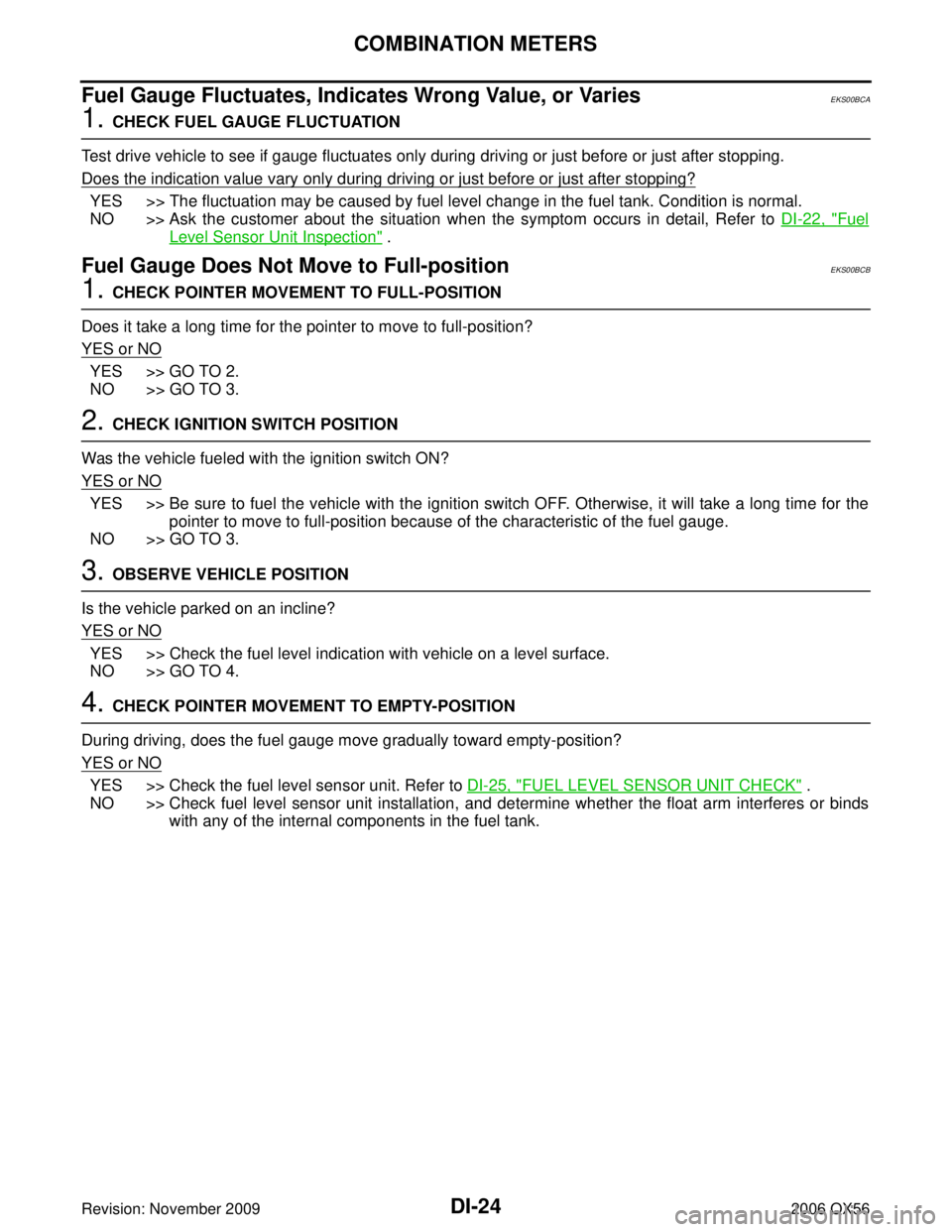
Fuel Gauge Fluctuates, Indicates Wrong Value, or VariesEKS00BCA
1. CHECK FUEL GAUGE FLUCTUATION
Test drive vehicle to see if gauge fluctuates only during driving or just before or just after stopping.
Does the indication value vary only during driving or just before or just after stopping?
YES >> The fluctuation may be caused by fuel level change in the fuel tank. Condition is normal.
NO >> Ask the customer about the situation when the symptom occurs in detail, Refer to DI-22, "
Fuel
Level Sensor Unit Inspection" .
Fuel Gauge Does Not Move to Full-positionEKS00BCB
1. CHECK POINTER MOVEMENT TO FULL-POSITION
Does it take a long time for the pointer to move to full-position?
YES or NO
YES >> GO TO 2.
NO >> GO TO 3.
2. CHECK IGNITION SWITCH POSITION
Was the vehicle fueled with the ignition switch ON?
YES or NO
YES >> Be sure to fuel the vehicle with the ignition switch OFF. Otherwise, it will take a long time for the pointer to move to full-position because of the characteristic of the fuel gauge.
NO >> GO TO 3.
3. OBSERVE VEHICLE POSITION
Is the vehicle parked on an incline?
YES or NO
YES >> Check the fuel level indication with vehicle on a level surface.
NO >> GO TO 4.
4. CHECK POINTER MOVEMENT TO EMPTY-POSITION
During driving, does the fuel gauge move gradually toward empty-position?
YES or NO
YES >> Check the fuel level sensor unit. Refer to DI-25, "FUEL LEVEL SENSOR UNIT CHECK" .
NO >> Check fuel level sensor unit installation, and determine whether the float arm interferes or binds with any of the internal components in the fuel tank.
Page 1146 of 3383
COMBINATION METERSDI-25
C
DE
F
G H
I
J
L
M A
B
DI
Revision: November 2009 2006 QX56
Electrical Components InspectionEKS00BCC
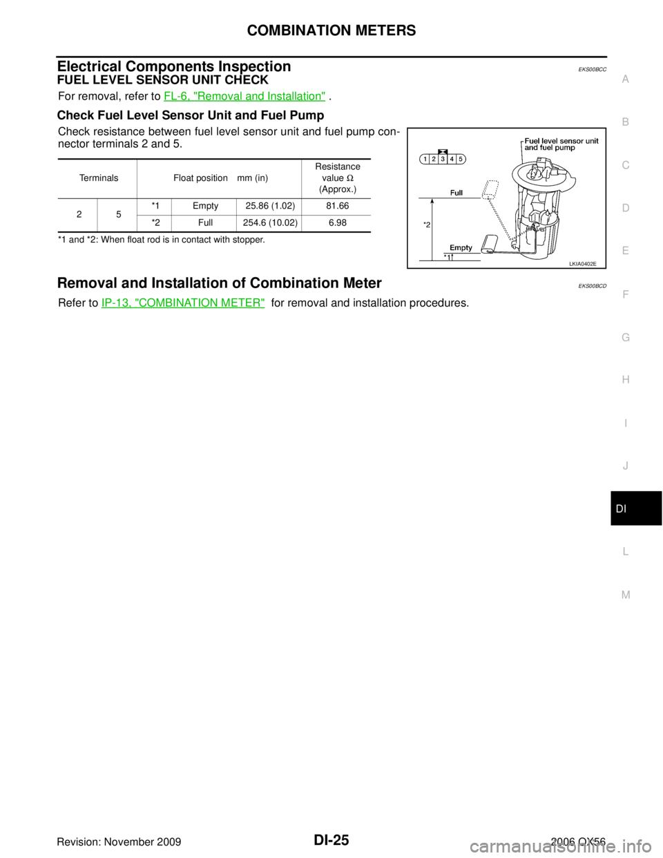
FUEL LEVEL SENSOR UNIT CHECK
For removal, refer to FL-6, "Removal and Installation" .
Check Fuel Level Sensor Unit and Fuel Pump
Check resistance between fuel level sensor unit and fuel pump con-
nector terminals 2 and 5.
*1 and *2: When float rod is in contact with stopper.
Removal and Installation of Combination MeterEKS00BCD
Refer to IP-13, "COMBINATION METER" for removal and installation procedures.
Terminals Float position mm (in) Resistance
value Ω
(Approx.)
25 *1 Empty 25.86 (1.02) 81.66
*2 Full 254.6 (10.02) 6.98
LKIA0402E
Page 1212 of 3383

EC-1
ENGINE CONTROL SYSTEM
B ENGINE
CONTENTS
C
DE
F
G H
I
J
K L
M
SECTION
A
EC
Revision: November 2009 2006 QX56
INDEX FOR DTC ...................................................
..... 8
DTC No. Index .................................................... ..... 8
Alphabetical Index ............................................... ... 12
PRECAUTIONS ..................................................... ... 16
Precautions for Supplemental Restraint System
(SRS) “AIR BAG” and “SEAT BELT PRE-TEN-
SIONER” ............................................................. ... 16
On Board Diagnostic (OBD) System of Engine and
A/T ....................................................................... ... 16
Precaution ........................................................... ... 16
PREPARATION ...................................................... ... 20
Special Service Tools .......................................... ... 20
Commercial Service Tools ................................... ... 22
ENGINE CONTROL SYSTEM ............................... ... 23
System Diagram .................................................. ... 23
Multiport Fuel Injection (MFI) System ................. ... 24
Electronic Ignition (EI) System ............................ ... 26
Fuel Cut Control (at No Load and High Engine
Speed) ................................................................. ... 27
AIR CONDITIONING CUT CONTROL .................. ... 28
Input/Output Signal Chart .................................... ... 28
System Description ............................................. ... 28
AUTOMATIC SPEED CONTROL DEVICE (ASCD) ... 29
System Description ............................................. ... 29
Component Description ....................................... ... 30
CAN COMMUNICATION ....................................... ... 31
System Description ............................................. ... 31
EVAPORATIVE EMISSION SYSTEM .................... ... 32
Description .......................................................... ... 32
Component Inspection ........................................ ... 35
Removal and Installation ..................................... ... 36
How to Detect Fuel Vapor Leakage .................... ... 37
ON BOARD REFUELING VAPOR RECOVERY
(ORVR) ................................................................... ... 39
System Description ............................................. ... 39
Diagnostic Procedure .......................................... ... 40
Component Inspection ........................................ ... 43
POSITIVE CRANKCASE VENTILATION .............. ... 45
Description .......................................................... ... 45
Component Inspection ........................................ ... 45IVIS (INFINITI VEHICLE IMMOBILIZER SYSTEM-
NATS) .....................................................................
... 47
Description ........................................................... ... 47
ON BOARD DIAGNOSTIC (OBD) SYSTEM ......... ... 48
Introduction .......................................................... ... 48
Two Trip Detection Logic ..................................... ... 48
Emission-related Diagnostic Information ............. ... 49
Malfunction Indicator Lamp (MIL) ........................ ... 63
OBD System Operation Chart ............................. ... 65
BASIC SERVICE PROCEDURE ............................ ... 71
Basic Inspection ..................................................... 71
Idle Speed and Ignition Timing Check ................. ... 76
VIN Registration ..................................................... 77
Accelerator Pedal Released Position Learning ... ... 78
Throttle Valve Closed Position Learning .............. ... 78
Idle Air Volume Learning ..................................... ... 78
Fuel Pressure Check .............................................. 80
TROUBLE DIAGNOSIS ......................................... ... 83
Trouble Diagnosis Introduction ............................ ... 83
DTC Inspection Priority Chart .............................. ... 89
Fail-safe Chart ..................................................... ... 91
Symptom Matrix Chart ......................................... ... 92
Engine Control Component Parts Location ......... ... 96
Vacuum Hose Drawing ........................................ .102
Circuit Diagram .................................................... .103
ECM Harness Connector Terminal Layout .......... .105
ECM Terminals and Reference Value .................. .105
CONSULT-II Function (ENGINE) ......................... .114
Generic Scan Tool (GST) Function ...................... .127
CONSULT-II Reference Value in Data Monitor .... .129
Major Sensor Reference Graph in Data Monitor
Mode .................................................................... .132
TROUBLE DIAGNOSIS - SPECIFICATION VALUE .134
Description ........................................................... .134
Testing Condition ................................................. .134
Inspection Procedure ........................................... .134
Diagnostic Procedure .......................................... .135
TROUBLE DIAGNOSIS FOR INTERMITTENT INCI-
DENT ...................................................................... .144
Page 1214 of 3383
EC-3
C
DE
F
G H
I
J
K L
M
EC A
Revision: November 2009 2006 QX56
. 223
On Board Diagnosis Logic .................................. . 223
DTC Confirmation Procedure .............................. . 223
Wiring Diagram ................................................... . 225
Diagnostic Procedure .......................................... . 228
Removal and Installation ..................................... . 231
DTC P0132, P0152 A/F SENSOR 1 ...................... . 232
Component Description ....................................... . 232
CONSULT-II Reference Value in Data Monitor Mode . 232
On Board Diagnosis Logic .................................. . 232
DTC Confirmation Procedure .............................. . 232
Wiring Diagram ................................................... . 234
Diagnostic Procedure .......................................... . 237
Removal and Installation ..................................... . 240
DTC P0133, P0153 A/F SENSOR 1 ...................... . 241
Component Description ....................................... . 241
CONSULT-II Reference Value in Data Monitor Mode . 241
On Board Diagnosis Logic .................................. . 241
DTC Confirmation Procedure .............................. . 242
Wiring Diagram ................................................... . 244
Diagnostic Procedure .......................................... . 247
Removal and Installation ..................................... . 252
DTC P0137, P0157 HO2S2 ................................... . 253
Component Description ....................................... . 253
CONSULT-II Reference Value in Data Monitor Mode . 253
On Board Diagnosis Logic .................................. . 253
DTC Confirmation Procedure .............................. . 254
Overall Function Check ....................................... . 254
Wiring Diagram ................................................... . 256
Diagnostic Procedure .......................................... . 259
Component Inspection ........................................ . 262
Removal and Installation ..................................... . 263
DTC P0138, P0158 HO2S2 ................................... . 264
Component Description ....................................... . 264
CONSULT-II Reference Value in Data Monitor Mode . 264
On Board Diagnosis Logic .................................. . 264
DTC Confirmation Procedure .............................. . 265
Overall Function Check ....................................... . 266
Wiring Diagram ................................................... . 267
Diagnostic Procedure .......................................... . 270
Component Inspection ........................................ . 275
Removal and Installation ..................................... . 276
DTC P0139, P0159 HO2S2 ................................... . 277
Component Description ....................................... . 277
CONSULT-II Reference Value in Data Monitor Mode . 277
On Board Diagnosis Logic .................................. . 277
DTC Confirmation Procedure .............................. . 278
Overall Function Check ....................................... . 278
Wiring Diagram ................................................... . 280
Diagnostic Procedure .......................................... . 283
Component Inspection ........................................ . 286
Removal and Installation ..................................... . 287
DTC P0171, P0174 FUEL INJECTION SYSTEM
FUNCTION ............................................................. . 288On Board Diagnosis Logic ...................................
.288
DTC Confirmation Procedure .............................. .288
Wiring Diagram .................................................... .290
Diagnostic Procedure .......................................... .294
DTC P0172, P0175 FUEL INJECTION SYSTEM
FUNCTION ............................................................. .299
On Board Diagnosis Logic ................................... .299
DTC Confirmation Procedure .............................. .299
Wiring Diagram .................................................... .301
Diagnostic Procedure .......................................... .305
DTC P0181 FTT SENSOR ..................................... .309
Component Description ....................................... .309
On Board Diagnosis Logic ................................... .309
DTC Confirmation Procedure .............................. .309
Wiring Diagram .................................................... .311
Diagnostic Procedure .......................................... .312
Component Inspection ......................................... .314
Removal and Installation ..................................... .314
DTC P0182, P0183 FTT SENSOR ......................... .315
Component Description ....................................... .315
On Board Diagnosis Logic ................................... .315
DTC Confirmation Procedure .............................. .315
Wiring Diagram .................................................... .316
Diagnostic Procedure .......................................... .317
Component Inspection ......................................... .319
Removal and Installation ..................................... .319
DTC P0222, P0223 TP SENSOR ........................... .320
Component Description ....................................... .320
CONSULT-II Reference Value in Data Monitor Mode .320
On Board Diagnosis Logic ................................... .320
DTC Confirmation Procedure .............................. .321
Wiring Diagram .................................................... .322
Diagnostic Procedure .......................................... .323
Component Inspection ......................................... .326
Removal and Installation ..................................... .326
DTC P0300 - P0308 MULTIPLE CYLINDER MIS-
FIRE, NO. 1 - 8 CYLINDER MISFIRE .................... .327
On Board Diagnosis Logic ................................... .327
DTC Confirmation Procedure .............................. .327
Diagnostic Procedure .......................................... .328
DTC P0327, P0328, P0332, P0333 KS .................. .335
Component Description ....................................... .335
On Board Diagnosis Logic ................................... .335
DTC Confirmation Procedure .............................. .335
Wiring Diagram .................................................... .336
Diagnostic Procedure .......................................... .337
Component Inspection ......................................... .339
Removal and Installation ..................................... .339
DTC P0335 CKP SENSOR (POS) ......................... .340
Component Description ....................................... .340
CONSULT-II Reference Value in Data Monitor Mode .340
On Board Diagnosis Logic ................................... .340
DTC Confirmation Procedure .............................. .340
Wiring Diagram .................................................... .342
Diagnostic Procedure .......................................... .343
Component Inspection ......................................... .346
Removal and Installation ..................................... .346
Page 1215 of 3383

EC-4Revision: November 20092006 QX56
DTC P0340 CMP SENSOR (PHASE) ....................
.347
Component Description ....................................... .347
On Board Diagnosis Logic ................................... .347
DTC Confirmation Procedure .............................. .347
Wiring Diagram .................................................... .349
Diagnostic Procedure .......................................... .350
Component Inspection ......................................... .353
Removal and Installation ..................................... .353
DTC P0420, P0430 THREE WAY CATALYST FUNC-
TION ....................................................................... .354
On Board Diagnosis Logic ................................... .354
DTC Confirmation Procedure .............................. .354
Overall Function Check ....................................... .355
Diagnostic Procedure .......................................... .356
DTC P0441 EVAP CONTROL SYSTEM ................ .360
System Description .............................................. .360
On Board Diagnosis Logic ................................... .360
DTC Confirmation Procedure .............................. .360
Overall Function Check ....................................... .361
Diagnostic Procedure .......................................... .362
DTC P0442 EVAP CONTROL SYSTEM ................ .365
On Board Diagnosis Logic ................................... .365
DTC Confirmation Procedure .............................. .366
Diagnostic Procedure .......................................... .367
DTC P0443 EVAP CANISTER PURGE VOLUME
CONTROL SOLENOID VALVE .............................. .373
Description ........................................................... .373
CONSULT-II Reference Value in Data Monitor Mode .373
On Board Diagnosis Logic ................................... .374
DTC Confirmation Procedure .............................. .374
Wiring Diagram .................................................... .375
Diagnostic Procedure .......................................... .377
Component Inspection ......................................... .380
Removal and Installation ..................................... .380
DTC P0444, P0445 EVAP CANISTER PURGE VOL-
UME CONTROL SOLENOID VALVE ..................... .381
Description ........................................................... .381
CONSULT-II Reference Value in Data Monitor Mode .381
On Board Diagnosis Logic ................................... .382
DTC Confirmation Procedure .............................. .382
Wiring Diagram .................................................... .383
Diagnostic Procedure .......................................... .385
Component Inspection ......................................... .386
Removal and Installation ..................................... .387
DTC P0447 EVAP CANISTER VENT CONTROL
VALVE .................................................................... .388
Component Description ....................................... .388
CONSULT-II Reference Value in Data Monitor Mode .388
On Board Diagnosis Logic ................................... .388
DTC Confirmation Procedure .............................. .389
Wiring Diagram .................................................... .390
Diagnostic Procedure .......................................... .391
Component Inspection ......................................... .393
DTC P0448 EVAP CANISTER VENT CONTROL
VALVE .................................................................... .395
Component Description ....................................... .395CONSULT-II Reference Value in Data Monitor Mode
.395
On Board Diagnosis Logic ................................... .395
DTC Confirmation Procedure ............................... .396
Wiring Diagram .................................................... .397
Diagnostic Procedure ........................................... .398
Component Inspection ......................................... .400
DTC P0451 EVAP CONTROL SYSTEM PRESSURE
SENSOR ................................................................. .402
Component Description ....................................... .402
CONSULT-II Reference Value in Data Monitor Mode .402
On Board Diagnosis Logic ................................... .402
DTC Confirmation Procedure ............................... .403
Diagnostic Procedure ........................................... .403
Component Inspection ......................................... .404
DTC P0452 EVAP CONTROL SYSTEM PRESSURE
SENSOR ................................................................. .405
Component Description ....................................... .405
CONSULT-II Reference Value in Data Monitor Mode .405
On Board Diagnosis Logic ................................... .405
DTC Confirmation Procedure ............................... .406
Wiring Diagram .................................................... .407
Diagnostic Procedure ........................................... .408
Component Inspection ......................................... .410
DTC P0453 EVAP CONTROL SYSTEM PRESSURE
SENSOR ................................................................. .411
Component Description ....................................... .411
CONSULT-II Reference Value in Data Monitor Mode .411
On Board Diagnosis Logic ................................... .411
DTC Confirmation Procedure ............................... .412
Wiring Diagram .................................................... .413
Diagnostic Procedure ........................................... .414
Component Inspection ......................................... .418
DTC P0455 EVAP CONTROL SYSTEM ................ .419
On Board Diagnosis Logic ................................... .419
DTC Confirmation Procedure ............................... .420
Diagnostic Procedure ........................................... .421
DTC P0456 EVAP CONTROL SYSTEM ................ .427
On Board Diagnosis Logic ................................... .427
DTC Confirmation Procedure ............................... .428
Overall Function Check ........................................ .429
Diagnostic Procedure ........................................... .430
DTC P0460 FUEL LEVEL SENSOR ...................... .436
Component Description ....................................... .436
On Board Diagnosis Logic ................................... .436
DTC Confirmation Procedure ............................... .436
Diagnostic Procedure ........................................... .437
Removal and Installation ...................................... .437
DTC P0461 FUEL LEVEL SENSOR ...................... .438
Component Description ....................................... .438
On Board Diagnosis Logic ................................... .438
Overall Function Check ........................................ .438
Diagnostic Procedure ........................................... .439
Removal and Installation ...................................... .439
DTC P0462, P0463 FUEL LEVEL SENSOR CIR-
CUIT ........................................................................ .440
Page 1218 of 3383
EC-7
C
DE
F
G H
I
J
K L
M
EC A
Revision: November 2009 2006 QX56
Diagnostic Procedure ..........................................
. 588
Component Inspection ........................................ . 592
ASCD INDICATOR ................................................ . 593
Component Description ....................................... . 593
CONSULT-II Reference Value in Data Monitor Mode . 593
Wiring Diagram ................................................... . 594
Diagnostic Procedure .......................................... . 595
ELECTRICAL LOAD SIGNAL ............................... . 596
Description .......................................................... . 596
CONSULT-II Reference Value in Data Monitor Mode . 596
Diagnostic Procedure .......................................... . 596
FUEL INJECTOR ................................................... . 598
Component Description ....................................... . 598
CONSULT-II Reference Value in Data Monitor Mode . 598
Wiring Diagram ................................................... . 599
Diagnostic Procedure .......................................... . 600
Component Inspection ........................................ . 603
Removal and Installation ..................................... . 603
FUEL PUMP .......................................................... . 604
Description .......................................................... . 604
CONSULT-II Reference Value in Data Monitor Mode . 604
Wiring Diagram ................................................... . 605
Diagnostic Procedure .......................................... . 606
Component Inspection ........................................ . 609
Removal and Installation ..................................... . 609
ICC BRAKE SWITCH ............................................ . 610
Component Description ....................................... . 610
CONSULT-II Reference Value in Data Monitor Mode .610
Wiring Diagram .................................................... .611
Diagnostic Procedure .......................................... .612
Component Inspection ......................................... .617
IGNITION SIGNAL ................................................. .618
Component Description ....................................... .618
Wiring Diagram .................................................... .619
Diagnostic Procedure .......................................... .624
Component Inspection ......................................... .628
Removal and Installation ..................................... .629
REFRIGERANT PRESSURE SENSOR ................. .630
Component Description ....................................... .630
Wiring Diagram .................................................... .631
Diagnostic Procedure .......................................... .632
Removal and Installation ..................................... .634
MIL AND DATA LINK CONNECTOR ..................... .635
Wiring Diagram .................................................... .635
SERVICE DATA AND SPECIFICATIONS (SDS) ... .637
Fuel Pressure ...................................................... .637
Idle Speed and Ignition Timing ............................ .637
Calculated Load Value ......................................... .637
Mass Air Flow Sensor .......................................... .637
Intake Air Temperature Sensor ............................ .637
Engine Coolant Temperature Sensor .................. .637
A/F Sensor 1 Heater ............................................ .637
Heated Oxygen sensor 2 Heater ......................... .637
Crankshaft Position Sensor (POS) ...................... .637
Camshaft Position Sensor (PHASE) ................... .637
Throttle Control Motor .......................................... .637
Fuel Injector ......................................................... .638
Fuel Pump ........................................................... .638
Page 1220 of 3383
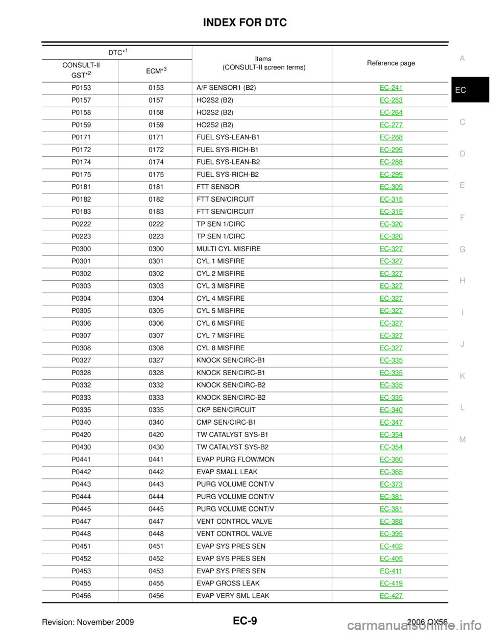
INDEX FOR DTCEC-9
C
DE
F
G H
I
J
K L
M A
EC
Revision: November 2009 2006 QX56P01530153 A/F SENSOR1 (B2) EC-241
P01570157 HO2S2 (B2) EC-253
P01580158 HO2S2 (B2) EC-264
P01590159 HO2S2 (B2) EC-277
P01710171 FUEL SYS-LEAN-B1 EC-288
P01720172 FUEL SYS-RICH-B1 EC-299
P01740174 FUEL SYS-LEAN-B2 EC-288
P01750175 FUEL SYS-RICH-B2 EC-299
P01810181 FTT SENSOR EC-309
P01820182 FTT SEN/CIRCUIT EC-315
P01830183 FTT SEN/CIRCUIT EC-315
P02220222 TP SEN 1/CIRC EC-320
P02230223 TP SEN 1/CIRC EC-320
P03000300 MULTI CYL MISFIRE EC-327
P03010301 CYL 1 MISFIRE EC-327
P03020302 CYL 2 MISFIRE EC-327
P03030303 CYL 3 MISFIRE EC-327
P03040304 CYL 4 MISFIRE EC-327
P03050305 CYL 5 MISFIRE EC-327
P03060306 CYL 6 MISFIRE EC-327
P03070307 CYL 7 MISFIRE EC-327
P03080308 CYL 8 MISFIRE EC-327
P03270327 KNOCK SEN/CIRC-B1 EC-335
P03280328 KNOCK SEN/CIRC-B1 EC-335
P03320332 KNOCK SEN/CIRC-B2 EC-335
P03330333 KNOCK SEN/CIRC-B2 EC-335
P03350335 CKP SEN/CIRCUIT EC-340
P03400340 CMP SEN/CIRC-B1 EC-347
P04200420 TW CATALYST SYS-B1 EC-354
P04300430 TW CATALYST SYS-B2 EC-354
P04410441 EVAP PURG FLOW/MON EC-360
P04420442 EVAP SMALL LEAK EC-365
P04430443 PURG VOLUME CONT/V EC-373
P04440444 PURG VOLUME CONT/V EC-381
P04450445 PURG VOLUME CONT/V EC-381
P04470447 VENT CONTROL VALVE EC-388
P04480448 VENT CONTROL VALVE EC-395
P04510451 EVAP SYS PRES SEN EC-402
P04520452 EVAP SYS PRES SEN EC-405
P04530453 EVAP SYS PRES SEN EC-411
P04550455 EVAP GROSS LEAK EC-419
P04560456 EVAP VERY SML LEAK EC-427
DTC*1
Items
(CONSULT-II screen terms) Reference page
CONSULT-II
GST*
2ECM*3
Page 1221 of 3383
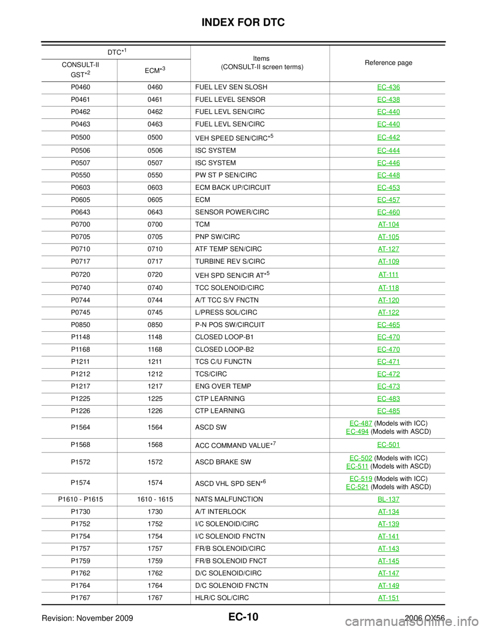
EC-10Revision: November 2009
INDEX FOR DTC
2006 QX56
P04600460 FUEL LEV SEN SLOSH EC-436
P04610461 FUEL LEVEL SENSOR EC-438
P04620462 FUEL LEVL SEN/CIRC EC-440
P04630463 FUEL LEVL SEN/CIRC EC-440
P05000500
VEH SPEED SEN/CIRC*5EC-442
P0506 0506 ISC SYSTEM EC-444
P05070507 ISC SYSTEM EC-446
P05500550 PW ST P SEN/CIRC EC-448
P06030603 ECM BACK UP/CIRCUIT EC-453
P06050605 ECM EC-457
P06430643 SENSOR POWER/CIRC EC-460
P07000700 TCM AT-104
P07050705 PNP SW/CIRC AT-105
P07100710 ATF TEMP SEN/CIRC AT-127
P07170717 TURBINE REV S/CIRC AT-109
P07200720
VEH SPD SEN/CIR AT*5AT- 111
P0740 0740 TCC SOLENOID/CIRC AT- 11 8
P07440744 A/T TCC S/V FNCTN AT-120
P07450745 L/PRESS SOL/CIRC AT-122
P08500850 P-N POS SW/CIRCUIT EC-465
P11481148 CLOSED LOOP-B1 EC-470
P11681168 CLOSED LOOP-B2 EC-470
P12111211 TCS C/U FUNCTN EC-471
P12121212 TCS/CIRC EC-472
P12171217 ENG OVER TEMP EC-473
P12251225 CTP LEARNING EC-483
P12261226 CTP LEARNING EC-485
P15641564 ASCD SW EC-487 (Models with ICC)
EC-494
(Models with ASCD)
P1568 1568
ACC COMMAND VALUE*
7EC-501
P1572 1572 ASCD BRAKE SW EC-502 (Models with ICC)
EC-511
(Models with ASCD)
P1574 1574
ASCD VHL SPD SEN*
6EC-519 (Models with ICC)
EC-521
(Models with ASCD)
P1610 - P1615 1610 - 1615 NATS MALFUNCTION BL-137
P17301730 A/T INTERLOCK AT-134
P17521752 I/C SOLENOID/CIRC AT-139
P17541754 I/C SOLENOID FNCTN AT-141
P17571757 FR/B SOLENOID/CIRC AT-143
P17591759 FR/B SOLENOID FNCT AT-145
P17621762 D/C SOLENOID/CIRC AT-147
P17641764 D/C SOLENOID FNCTN AT-149
P17671767 HLR/C SOL/CIRC AT-151
DTC*1
Items
(CONSULT-II screen terms) Reference page
CONSULT-II
GST*
2ECM*3