Page 1201 of 3383
DI-80
REAR VIEW MONITOR
Revision: November 20092006 QX56
CONSULT-II Function (REARVIEW CAMERA)EKS00BDK
CONSULT-II can display each diagnostic item using the diagnostic test modes shown following.
CONSULT-II BASIC OPERATION
CAUTION:
If CONSULT-II is used with no connection of CONSULT-II CONVERTER, malfunctions might be
detected in self-diagnosis depending on control unit which carries out CAN communication.
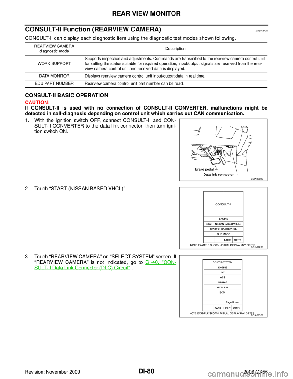
1. With the ignition switch OFF, connect CONSULT-II and CON-
SULT-II CONVERTER to the data link connector, then turn igni-
tion switch ON.
2. Touch “START (NISSAN BASED VHCL) ”.
3. Touch “REARVIEW CAMERA ” on “SELECT SYSTEM ” screen. If
“REARVIEW CAMERA ” is not indicated, go to GI-40, "
CON-
SULT-II Data Link Connector (DLC) Circuit" .
REARVIEW CAMERA
diagnostic mode Description
WORK SUPPORT Supports inspection and adjustments. Commands are transmitted to the rearview camera control unit
for setting the status suitable for required operation, input/output signals are received from the rear-
view camera control unit and received data is displayed.
DATA MONITOR Displays rearview camera control unit input/output data in real time.
ECU PART NUMBER Rearview camera control unit part number can be read.
BBIA0369E
BCIA0029E
BCIA0030E
Page 1202 of 3383
REAR VIEW MONITORDI-81
C
DE
F
G H
I
J
L
M A
B
DI
Revision: November 2009 2006 QX56
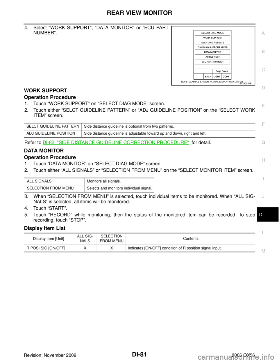
4. Select “WORK SUPPORT ”, “DATA MONITOR ” or “ECU PART
NUMBER ”.
WORK SUPPORT
Operation Procedure
1. Touch “WORK SUPPORT ” on “SELECT DIAG MODE ” screen.
2. Touch either “SELCT GUIDELINE PATTERN ” or “ADJ GUIDELINE POSITION” on the “SELECT WORK
ITEM ” screen.
Refer to DI-82, "
SIDE DISTANCE GUIDELINE CORRECTION PROCEDURE" for detail.
DATA MONITOR
Operation Procedure
1. Touch “DATA MONITOR ” on “SELECT DIAG MODE ” screen.
2. Touch either “ALL SIGNALS” or “SELECTION FROM MENU ” on the “SELECT MONITOR ITEM ” screen.
3. When “SELECTION FROM MENU ” is selected, touch individual items to be monitored. When “ALL SIG-
NALS ” is selected, all items will be monitored.
4. Touch “START”.
5. Touch “RECORD” while monitoring, then the status of the monitored item can be recorded. To stop
recording, touch “STOP”.
Display Item List
BCIA0031E
SELCT GUIDELINE PATTERN Side distance guideline is optional from two patterns.
ADJ GUIDELINE POSITION Side distance guideline is adjustable toward up and down, right and left.
ALL SIGNALS Monitors all signals.
SELECTION FROM MENU Selects and monitors individual signal.
Display item [Unit] ALL SIG-
NALS SELECTION
FROM MENU Contents
R POSI SIG [ON/OFF] X X Indicates [ON/OFF] condition of R position signal input.
Page 1206 of 3383
REAR VIEW MONITORDI-85
C
DE
F
G H
I
J
L
M A
B
DI
Revision: November 2009 2006 QX56
Rear View Is Not Displayed With The A/T Selector Lever In R PositionEKS00BDN
1. BACK-UP LAMP INSPECTION
1. Turn ignition switch ON.
2. Shift A/T selector lever to R position.
Does back-up lamp illuminate?
YES >> GO TO 2.
NO >> Check back-up lamp system. Refer to LT- 1 0 9 , "
BACK-UP LAMP" .
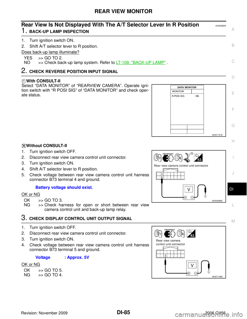
2. CHECK REVERSE POSITION INPUT SIGNAL
With CONSULT-II
Select “DATA MONITOR” of “REARVIEW CAMERA ”. Operate igni-
tion switch with “R POSI SIG” of “DATA MONITOR” and check oper-
ate status.
Without CONSULT-II
1. Turn ignition switch OFF.
2. Disconnect rear view camera control unit connector.
3. Turn ignition switch ON.
4. Shift A/T selector lever to R position.
5. Check voltage between rear view camera control unit harness connector B73 terminal 4 and ground.
OK or NG
OK >> GO TO 3.
NG >> Check harness for open or short between rear view camera control unit and back-up lamp relay.
3. CHECK DISPLAY CONTROL UNIT OUTPUT SIGNAL
1. Turn ignition switch OFF.
2. Disconnect rear view camera control unit connector.
3. Turn ignition switch ON.
4. Check voltage between rear view camera control unit harness connector B73 terminal 5 and ground.
OK or NG
OK >> GO TO 5.
NG >> GO TO 4.
SKIA7147E
Battery voltage should exist.
SKIA5086E
Voltage : Approx. 5V
SKIA7148E
Page 1207 of 3383
DI-86
REAR VIEW MONITOR
Revision: November 20092006 QX56
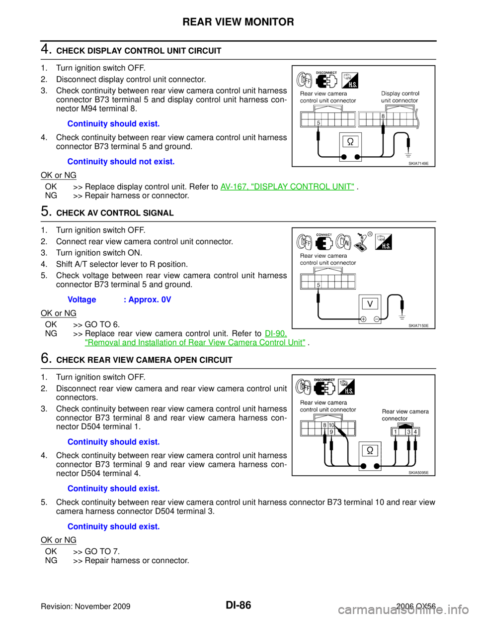
4. CHECK DISPLAY CONTROL UNIT CIRCUIT
1. Turn ignition switch OFF.
2. Disconnect display control unit connector.
3. Check continuity between rear view camera control unit harness connector B73 terminal 5 and display control unit harness con-
nector M94 terminal 8.
4. Check continuity between rear view camera control unit harness connector B73 terminal 5 and ground.
OK or NG
OK >> Replace display control unit. Refer to AV- 1 6 7 , "DISPLAY CONTROL UNIT" .
NG >> Repair harness or connector.
5. CHECK AV CONTROL SIGNAL
1. Turn ignition switch OFF.
2. Connect rear view camera control unit connector.
3. Turn ignition switch ON.
4. Shift A/T selector lever to R position.
5. Check voltage between rear view camera control unit harness connector B73 terminal 5 and ground.
OK or NG
OK >> GO TO 6.
NG >> Replace rear view camera control unit. Refer to DI-90,
"Removal and Installation of Rear View Camera Control Unit" .
6. CHECK REAR VIEW CAMERA OPEN CIRCUIT
1. Turn ignition switch OFF.
2. Disconnect rear view camera and rear view camera control unit connectors.
3. Check continuity between rear view camera control unit harness connector B73 terminal 8 and rear view camera harness con-
nector D504 terminal 1.
4. Check continuity between rear view camera control unit harness connector B73 terminal 9 and rear view camera harness con-
nector D504 terminal 4.
5. Check continuity between rear view camera control unit harness connector B73 terminal 10 and rear view camera harness connector D504 terminal 3.
OK or NG
OK >> GO TO 7.
NG >> Repair harness or connector. Continuity should exist.
Continuity should not exist.
SKIA7149E
Voltage : Approx. 0V
SKIA7150E
Continuity should exist.
Continuity should exist.
Continuity should exist.
SKIA5095E
Page 1209 of 3383
DI-88
REAR VIEW MONITOR
Revision: November 20092006 QX56
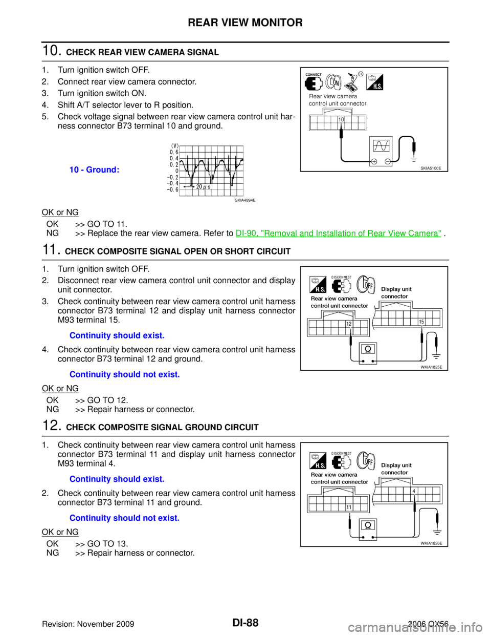
10. CHECK REAR VIEW CAMERA SIGNAL
1. Turn ignition switch OFF.
2. Connect rear view camera connector.
3. Turn ignition switch ON.
4. Shift A/T selector lever to R position.
5. Check voltage signal between rear view camera control unit har- ness connector B73 terminal 10 and ground.
OK or NG
OK >> GO TO 11.
NG >> Replace the rear view camera. Refer to DI-90, "
Removal and Installation of Rear View Camera" .
11 . CHECK COMPOSITE SIGNAL OPEN OR SHORT CIRCUIT
1. Turn ignition switch OFF.
2. Disconnect rear view camera control unit connector and display unit connector.
3. Check continuity between rear view camera control unit harness connector B73 terminal 12 and display unit harness connector
M93 terminal 15.
4. Check continuity between rear view camera control unit harness connector B73 terminal 12 and ground.
OK or NG
OK >> GO TO 12.
NG >> Repair harness or connector.
12. CHECK COMPOSITE SIGNAL GROUND CIRCUIT
1. Check continuity between rear view camera control unit harness connector B73 terminal 11 and display unit harness connector
M93 terminal 4.
2. Check continuity between rear view camera control unit harness connector B73 terminal 11 and ground.
OK or NG
OK >> GO TO 13.
NG >> Repair harness or connector. 10 - Ground:
SKIA5100E
SKIA4894E
Continuity should exist.
Continuity should not exist.
WKIA1825E
Continuity should exist.
Continuity should not exist.
WKIA1826E
Page 1210 of 3383
REAR VIEW MONITORDI-89
C
DE
F
G H
I
J
L
M A
B
DI
Revision: November 2009 2006 QX56
13. CHECK REAR VIEW CAMERA CONTROL UNIT COMPOSITE SIGNAL
1. Connect rear view camera control unit connector and display unit connector.
2. Turn ignition switch ON.
3. Check voltage signal between rear view camera control unit har- ness connector B73 terminal 12 and ground.
OK or NG
OK >> Replace the display unit. Refer to AV- 1 6 7 , "DISPLAY UNIT" .
NG >> Replace the rear view camera control unit. Refer to DI-90, "
Removal and Installation of Rear View
Camera Control Unit" .
12 - Ground:
WKIA1827E
SKIA4896E
Page 1219 of 3383
EC-8Revision: November 2009
INDEX FOR DTC
2006 QX56
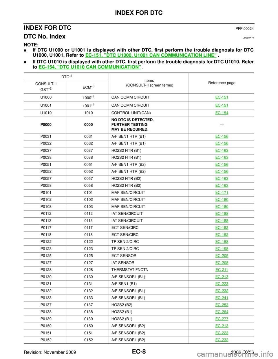
INDEX FOR DTCPFP:00024
DTC No. IndexUBS00KYY
NOTE:
�If DTC U1000 or U1001 is displayed with other DTC, first perform the trouble diagnosis for DTC
U1000, U1001. Refer to EC-151, "
DTC U1000, U1001 CAN COMMUNICATION LINE" .
�If DTC U1010 is displayed with other DTC, first perform the trouble diagnosis for DTC U1010. Refer
to EC-154, "
DTC U1010 CAN COMMUNICATION" .
DTC*1
Items
(CONSULT-II screen terms) Reference page
CONSULT-II
GST*
2ECM*3
U1000 1000*4CAN COMM CIRCUIT EC-151
U1001
1001*4CAN COMM CIRCUIT EC-151
U10101010 CONTROL UNIT(CAN) EC-154
P00000000NO DTC IS DETECTED.
FURTHER TESTING
MAY BE REQUIRED. —
P0031 0031 A/F SEN1 HTR (B1) EC-156
P00320032 A/F SEN1 HTR (B1) EC-156
P00370037 HO2S2 HTR (B1) EC-163
P00380038 HO2S2 HTR (B1) EC-163
P00510051 A/F SEN1 HTR (B2) EC-156
P00520052 A/F SEN1 HTR (B2) EC-156
P00570057 HO2S2 HTR (B2) EC-163
P00580058 HO2S2 HTR (B2) EC-163
P01010101 MAF SEN/CIRCUIT EC-171
P01020102 MAF SEN/CIRCUIT EC-180
P01030103 MAF SEN/CIRCUIT EC-180
P01120112 IAT SEN/CIRCUIT EC-188
P01130113 IAT SEN/CIRCUIT EC-188
P01170117 ECT SEN/CIRC EC-192
P01180118 ECT SEN/CIRC EC-192
P01220122 TP SEN 2/CIRC EC-198
P01230123 TP SEN 2/CIRC EC-198
P01250125 ECT SENSOR EC-205
P01270127 IAT SENSOR EC-208
P01280128 THERMSTAT FNCTN EC-211
P01300130 A/F SENSOR1 (B1) EC-213
P01310131 A/F SEN1 (B1) EC-223
P01320132 A/F SENSOR1 (B1) EC-232
P01330133 A/F SENSOR1 (B1) EC-241
P01370137 HO2S2 (B2) EC-253
P01380138 HO2S2 (B1) EC-264
P01390139 HO2S2 (B1) EC-277
P01500150 A/F SENSOR1 (B2) EC-213
P01510151 A/F SENSOR1 (B2) EC-223
P01520152 A/F SENSOR1 (B2) EC-232
Page 1223 of 3383

EC-12Revision: November 2009
INDEX FOR DTC
2006 QX56
Alphabetical IndexUBS00KYZ
NOTE:
�If DTC U1000 or U1001 is displayed with other DTC, first perform the trouble diagnosis for DTC
U1000, U1001. Refer to EC-151, "
DTC U1000, U1001 CAN COMMUNICATION LINE" .
�If DTC U1010 is displayed with other DTC, first perform the trouble diagnosis for DTC U1010. Refer
to EC-154, "
DTC U1010 CAN COMMUNICATION" .
Items
(CONSULT-II screen terms) DTC*
1
Reference page
CONSULT-II
GST*
2ECM*3
A/F SENSOR1 (B1) P01300130 EC-213
A/F SENSOR1 (B1) P01310131 EC-223
A/F SENSOR1 (B1) P01320132 EC-232
A/F SENSOR1 (B1) P01330133 EC-241
A/F SENSOR1 (B1) P2A002A00 EC-575
A/F SENSOR1 (B2) P01500150 EC-213
A/F SENSOR1 (B2) P01510151 EC-223
A/F SENSOR1 (B2) P01520152 EC-232
A/F SENSOR1 (B2) P01530153 EC-241
A/F SENSOR1 (B2) P2A032A03 EC-575
A/F SEN1 HTR (B1) P00310031 EC-156
A/F SEN1 HTR (B1) P00320032 EC-156
A/F SEN1 HTR (B2) P00510051 EC-156
A/F SEN1 HTR (B2) P00520052 EC-156
A/T INTERLOCK P17301730 AT-134
A/T TCC S/V FNCTN P07440744 AT-120
ACC COMMAND VALUE*7P15681568 EC-501
APP SEN 1/CIRC P21222122 EC-547
APP SEN 1/CIRC P21232123 EC-547
APP SEN 2/CIRC P21272127 EC-553
APP SEN 2/CIRC P21282128 EC-553
APP SENSOR P21382138 EC-567
ASCD BRAKE SW P15721572EC-502 (Models with ICC)
EC-511
(Models with ASCD)
ASCD SW P15641564EC-487
(Models with ICC)
EC-494
(Models with ASCD)
ASCD VHL SPD SEN*
6P1574 1574EC-519 (Models with ICC)
EC-521
(Models with ASCD)
ATF TEMP SEN/CIRC P0710 0710 AT-127
BRAKE SW/CIRCUITP18051805 EC-523
CAN COMM CIRCUIT U1000
1000*4EC-151
CAN COMM CIRCUIT U1001
1001*4EC-151
CKP SEN/CIRCUIT P03350335 EC-340
CLOSED LOOP-B1 P11481148 EC-470
CLOSED LOOP-B2 P11681168 EC-470
CMP SEN/CIRC-B1 P03400340 EC-347
CONTROL UNIT(CAN) U10101010 EC-154