Page 2801 of 3383

RF-26
SUNROOF
Revision: November 20092006 QX56
SUNROOF UNIT
Removal
CAUTION:
�Always work with a helper.
�When taking sunroof unit out, use shop cloths to protect the seats and trim from damage.
�After installing the sunroof unit and glass lid assembly, check gap adjustment to make sure there
is no malfunction.
1. Remove headlining. Refer to EI-38, "
HEADLINING" .
2. Remove the sunroof glass lid assembly. Refer to RF-26, "
GLASS LID ASSEMBLY" .
3. Remove overhead console bracket.
4. Disconnect front and rear drain hoses.
5. Remove front sunroof frame assembly bolts.
6. Remove rear sunroof bracket bolts.
7. Remove the sunroof frame assembly side bolts, then the sunroof unit.
Installation
1. Position the sunroof frame assembly and install the side bolts.
2. Install the sunroof brackets and bolts.
3. Install the front sunroof frame assembly bolts.
4. Connect front and rear drain hoses.
5. Install the overhead console bracket.
6. Install the sunroof glass lid assembly. Refer to RF-26, "
GLASS LID ASSEMBLY" .
NOTE:
Adjust sunroof glass lid assembly gap and height, refer to RF-23, "
Fitting Adjustment" .
7. Install headlining. Refer to EI-38, "
HEADLINING" .
GLASS LID ASSEMBLY
Removal
1. Open sunshade assembly.
NOTE:
Be sure glass lid assembly is fully closed.
2. Remove side cover LH and RH.
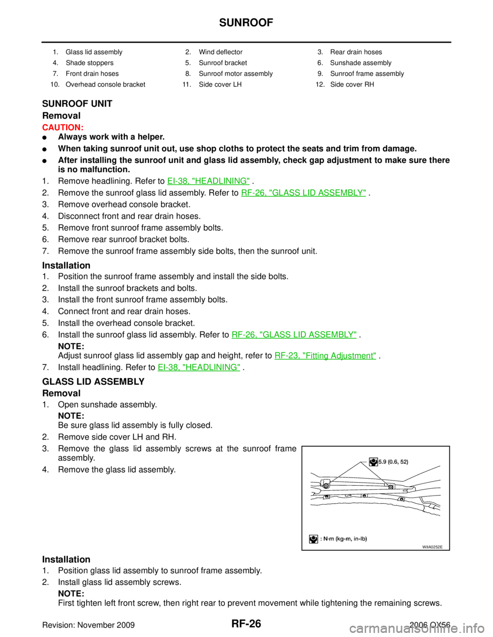
3. Remove the glass lid assembly screws at the sunroof frame assembly.
4. Remove the glass lid assembly.
Installation
1. Position glass lid assembly to sunroof frame assembly.
2. Install glass lid assembly screws. NOTE:
First tighten left front screw, then right rear to prevent movement while tightening the remaining screws.
1. Glass lid assembly 2. Wind deflector3. Rear drain hoses
4. Shade stoppers 5. Sunroof bracket 6. Sunshade assembly
7. Front drain hoses 8. Sunroof motor assembly9. Sunroof frame assembly
10. Overhead console bracket 11. Side cover LH 12. Side cover RH
WIIA0252E
Page 2821 of 3383

RFD-16
REAR FINAL DRIVE ASSEMBLY
Revision: November 20092006 QX56
ASSEMBLY INSPECTION AND ADJUSTMENT
�Drain the differential gear oil before inspection and adjustment. Refer to RFD-8, "DIFFERENTIAL GEAR
OIL" .
�Remove and install the carrier cover as necessary for inspection and adjustment. Refer to RFD-12, "CAR-
RIER COVER" .
Total Preload Torque
1. Remove the side flanges if necessary. Refer to RFD-19, "Side Flange" .
CAUTION:
The side flanges shaft must removed in order to measure total preload torque.
2. Rotate the drive pinion back and forth 2 to 3 times to check for unusual noise and rotation malfunction.
3. Rotate the drive pinion at least 20 times to check for smooth operation of the bearings.
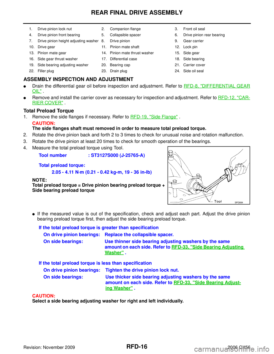
4. Measure the total preload torque using Tool.
NOTE:
Total preload torque = Drive pinion bearing preload torque +
Side bearing preload torque
�If the measured value is out of the specification, check and adjust each part. Adjust the drive pinion
bearing preload torque first, then adjust the side bearing preload torque.
CAUTION:
Select a side bearing adjusting washer for right and left individually.
1. Drive pinion lock nut 2. Companion flange 3. Front oil seal
4. Drive pinion front bearing 5. Collapsible spacer 6. Drive pinion rear bearing
7. Drive pinion height adjusting washer 8. Drive pinion 9. Gear carrier
10. Drive gear 11. Pinion mate shaft 12. Lock pin
13. Pinion mate gear 14. Pinion mate thrust washer 15. Side gear
16. Side gear thrust washer 17. Differential case 18. Side bearing
19. Side bearing adjusting washer 20. Bearing cap 21. Carrier cover
22. Filler plug 23. Drain plug 24. Side oil seal
Tool number : ST3127S000 (J-25765-A)
Total preload torque:
2.05 - 4.11 N·m (0.21 - 0.42 kg-m, 19 - 36 in-lb)
SPD884
If the total preload torque is greater than specificationOn drive pinion bearings: Replace the collapsible spacer.
On side bearings: Use thinner side bearing adjusting washers by the same amount on each side. Refer to RFD-33, "
Side Bearing Adjusting
Washer" .
If the total preload torque is less than specification On drive pinion bearings: Tighten the drive pinion lock nut.
On side bearings: Use thicker side bearing adjusting washers by the same amount on each side. Refer to RFD-33, "
Side Bearing Adjust-
ing Washer" .
Page 2867 of 3383

RSU-28
REAR SUSPENSION ASSEMBLY
Revision: November 20092006 QX56
Wheel Alignment InspectionEES001HH
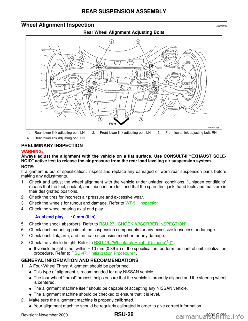
Rear Wheel Alignment Adjusting Bolts
PRELIMINARY INSPECTION
WARNING:
Always adjust the alignment with the vehicle on a flat surface. Use CONSULT-II “EXHAUST SOLE-
NOID” active test to release the air pressure from the rear load leveling air suspension system.
NOTE:
If alignment is out of specification, inspect and replace any damaged or worn rear suspension parts before
making any adjustments.
1. Check and adjust the wheel alignment with the vehicle under unladen conditions. “Unladen conditions”
means that the fuel, coolant, and lubricant are full; and that the spare tire, jack, hand tools and mats are in
their designated positions.
2. Check the tires for incorrect air pressure and excessive wear.
3. Check the wheels for runout and damage. Refer to WT-5, "
Inspection" .
4. Check the wheel bearing axial end play.
5. Check the shock absorbers. Refer to RSU-27, "
SHOCK ABSORBER INSPECTION" .
6. Check each mounting point of the suspension components for any excessive looseness or damage.
7. Check each link, arm, and the rear suspension member for any damage.
8. Check the vehicle height. Refer to RSU-49, "
Wheelarch Height (Unladen*1 )" .
�If vehicle height is not within ± 10 mm (0.39 in) of the specification, perform the control unit initialization
procedure. Refer to RSU-47, "
Initialization Procedure" .
GENERAL INFORMATION AND RECOMMENDATIONS
1. A Four-Wheel Thrust Alignment should be performed.
�This type of alignment is recommended for any NISSAN vehicle.
�The four-wheel “thrust” process helps ensure that the vehicle is properly aligned and the steering wheel
is centered.
�The alignment machine itself should be capable of accepting any NISSAN vehicle.
�The alignment machine should be checked to ensure that it is level.
2. Make sure the alignment machine is properly calibrated.
�Your alignment machine should be regularly calibrated in order to give correct information.
WEIA0102E
1. Rear lower link adjusting bolt, LH 2. Front lower link adjusting bolt, LH 3. Front lower link adjusting bolt, RH
4. Rear lower link adjusting bolt, RH
Axial end play : 0 mm (0 in)
Page:
< prev 1-8 9-16 17-24