Page 1692 of 3383

DTC P1217 ENGINE OVER TEMPERATUREEC-481
C
DE
F
G H
I
J
K L
M A
EC
Revision: November 2009 2006 QX56
5. CHECK INTERMITTENT INCIDENT
Perform EC-144, "
TROUBLE DIAGNOSIS FOR INTERMITTENT INCIDENT" .
OK or NG
OK >> Replace IPDM E/R. Refer to PG-18, "IPDM E/R (INTELLIGENT POWER DISTRIBUTION MOD-
ULE ENGINE ROOM)" .
NG >> Repair or replace harness connectors.
Main 12 Causes of OverheatingUBS00H8Z
*1: Turn the ignition switch ON.
*2: Engine running at 3,000 rpm for 10 minutes.
*3: Drive at 90 km/h (55 MPH) for 30 minutes and then let idle for 10 minutes.
*4: After 60 minutes of cool down time.
For more information, refer to CO-6, "
OVERHEATING CAUSE ANALYSIS" .
Engine Step Inspection item
EquipmentStandardReference page
OFF 1
�Blocked radiator
�Blocked condenser
�Blocked radiator grille
�Blocked bumper
�Visual No blocking —
2
�Coolant mixture�Coolant tester 50 - 50% coolant mixture MA-11, "RECOM-
MENDED FLUIDS AND
LUBRICANTS"
3�Coolant level�VisualCoolant up to MAX level
in reservoir tank and radi-
ator filler neck MA-13, "Changing
Engine Coolant"
4�Reservoir tank cap�Pressure tester 95 - 125 kPa
(0.97 - 1.28 kg/cm2 , 14 -
18 psi) (Limit) CO-10, "
CHECKING
RESERVOIR CAP"
ON*25�Coolant leaks�Visual
No leaks CO-10, "CHECKING
COOLING SYSTEM FOR
LEAKS"
ON*26�Thermostat�Touch the upper and
lower radiator hosesBoth hoses should be hot
CO-21, "THERMOSTAT
AND WATER PIPING"
ON*17�Cooling fan�CONSULT-IIOperating See trouble diagnosis for
DTC P1217 ( EC-473,
"DTC P1217 ENGINE
OVER TEMPERATURE"
).
OFF 8
�Combustion gas leak�Color checker chemical
tester 4 Gas analyzer Negative
—
ON*
39�Coolant temperature
gauge�Visual Gauge less than 3/4
when driving —
�Coolant overflow to
reservoir tank�Visual
No overflow during driving
and idling MA-13, "Changing
Engine Coolant"
OFF*410�Coolant return from
reservoir tank to radia-
tor�Visual
Should be initial level in
reservoir tank MA-13, "Changing
Engine Coolant"
OFF 11�Cylinder head�Straight gauge feeler
gauge0.1 mm (0.004 in) Maxi-
mum distortion (warping) EM-68, "Inspection After
Disassembly"
12�Cylinder block and pis-
tons�Visual
No scuffing on cylinder
walls or piston EM-94, "Inspection After
Disassembly"
Page 2121 of 3383

GI-30
SERVICE INFORMATION FOR ELECTRICAL INCIDENT
Revision: November 20092006 QX56
UNDER SEATING AREAS
An unclamped or loose harness can cause wiring to be pinched by seat components (such as slide guides)
during vehicle vibration. If the wiring runs under seating areas, inspect wire routing for possible damage or
pinching.
Heat Sensitive
The customer's concern may occur during hot weather or after car
has sat for a short time. In such cases you will want to check for a
heat sensitive condition.
To determine if an electrical component is heat sensitive, heat the
component with a heat gun or equivalent.
Do not heat components above 60°C (140 °F). If incident occurs
while heating the unit, either replace or properly insulate the compo-
nent.
Freezing
The customer may indicate the incident goes away after the car
warms up (winter time). The cause could be related to water freezing
somewhere in the wiring/electrical system.
There are two methods to check for this. The first is to arrange for
the owner to leave his car overnight. Make sure it will get cold
enough to demonstrate his complaint. Leave the car parked outside
overnight. In the morning, do a quick and thorough diagnosis of
those electrical components which could be affected.
The second method is to put the suspect component into a freezer
long enough for any water to freeze. Reinstall the part into the car
and check for the reoccurrence of the incident. If it occurs, repair or
replace the component.
Water Intrusion
The incident may occur only during high humidity or in rainy/snowy
weather. In such cases the incident could be caused by water intru-
sion on an electrical part. This can be simulated by soaking the car
or running it through a car wash.
Do not spray water directly on any electrical components.
Electrical Load
The incident may be electrical load sensitive. Perform diagnosis with
all accessories (including A/C, rear window defogger, radio, fog
lamps) turned on.
SGI842
SGI843
SGI844
SGI845
Page 3015 of 3383
SE-84
HEATED SEAT
Revision: November 20092006 QX56
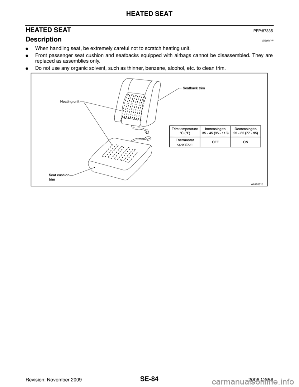
HEATED SEATPFP:87335
Description EIS004YP
�When handling seat, be extremely careful not to scratch heating unit.
�Front passenger seat cushion and seatbacks equipped with airbags cannot be disassembled. They are
replaced as assemblies only.
�Do not use any organic solvent, such as thinner, benzene, alcohol, etc. to clean trim.
WIIA0031E
Page 3023 of 3383
SE-92
FRONT SEAT
Revision: November 20092006 QX56
1. Headrest2. Headrest holder 3. Seatback assembly
4. Armrest assembly 5. Seat cushion trim cover 6. Seat cushion pad
7. Seat cushion heating element 8. Seat cushion frame 9. Seatbelt buckle assembly
10. Lifter motor link bar 11. Seat frame assembly 12. Seat cushion inner finisher
13. Seat lifter motor assembly 14. Seat spacer 15. Lock gear
16. Seat cushion front finisher 17. Flexible seat wire 18. Front seat slide motor assembly (LH)
19. Power seat memory module 20. Lifter motor bracket assembly 21. Driver seat wiring harness
22. Seat cushion outer finisher 23. Bolt cover 24. Outer pedestal finisher
25. LH outer leg cover 26. Seat slide/recline switch 27. Slide switch knob
28. Recliner switch knob 29. Power seat switch escutcheon 30. Lumbar switch bezel
31. Lumbar switch 32. Headrest holder with multi-position lock
Page 3029 of 3383
SE-98
SECOND SEAT
Revision: November 20092006 QX56
SECOND SEATPFP:88000
Removal and InstallationEIS007X1
SECOND ROW OUTBOARD
Removal
1. Remove seat base trim cover.
2. Lift handle and tilt seat forward.
3. DIsconnect the seat cushion heating element electrical connec-
tor.
4. Remove seat anchor nuts, bolts and seat assembly.
Installation
Installation is in the reverse order of removal.
SECOND ROW CENTER
Removal
1. Tilt the seat cushion forward.
2. Remove the seat anchor bolts.
3. Tilt the seat cushion back and remove the seat.
Installation
Installation is in the reverse order of removal.
LIIA1119E
LIIA1116E
Page 3031 of 3383
SE-100
SECOND SEAT
Revision: November 20092006 QX56
1. Headrest 2. Seatback pad 3. Seatback frame
4. Rear seat bezel 5. RH Headrest guide 6. LH Headrest guide
7. Seat back panel 8. Seat actuator assembly 9. Reclining device inner cover
10. Reclining device inner mid cover 11. Armrest assembly 12. Armrest bolt cover
13. Armrest trim cover 14. Latch assembly 15. Seat cushion mat springs
16. Seat cushion mat 17. Seat cushion frame assembly 18. Seat support trim cover
19. Seat support pad assembly 20. Lower rear seat cover 21. Lower rear seat cover inner
22. Outboard cushion floor latch 23. Seat cushion support frame assem- bly24. Lower rear seat cover outer
25. Seat cushion pad 26. Inner inboard reclining device cover 27. Outer inboard reclining device cover
28. Seat latch and recliner release 29. Reclining device outer mid cover 30. Reclining device lever
31. Reclining device outer cover 32. Seatback trim cover 33. Seat cushion trim cover
34. Seat cushion heating element
Page 3035 of 3383
SE-104
SECOND SEAT
Revision: November 20092006 QX56
7. Headrest8. Seat latch and recliner release 9. Reclining device outer cover
10. Reclining device lever 11. Reclining device outer mid cover 12. Outer inboard reclining device cover
13. Inner inboard reclining device cover 14. Seat cushion trim cover 15. Seat cushion pad
16. Seat cushion frame assembly 17. Lower rear seat cover outer 18. Outboard cushion floor latch
19. Seat cushion support frame assem- bly 20. Inboard cushion floor latch
21. Lower rear seat cover inner
22. Lower rear seat cover 23. Seat support pad assembly 24. Seat support trim cover
25. Seat cushion mat 26. Seat cushion mat springs 27. Latch assembly
28. Armrest assembly 29. Armrest trim cover 30. Reclining device outer cover
31. Reclining device inner mid cover 32. Seatback frame 33. Seat actuator assembly
34. Seat cushion heating element
Page:
< prev 1-8 9-16 17-24