PERIODIC MAINTENANCEMA-9
C
DE
F
G H
I
J
K
M A
B
MA
Revision: November 2009 2006 QX56
(1) If towing a trailer, or using a car-top carrier, or driving on rough or muddy roads, change (not just inspect) oil at every 30,000 miles
(48,000 km) or 24 months.
(2) Refer to “ Tire rotation” under the “General maintenance ” heading earlier in this section.
Schedule 2ELS001BM
EMISSION CONTROL SYSTEM MAINTENANCE
Abbreviations: R = Replace. I = Inspect. Correct or replace if necessary. [ ]: At the mileage intervals only
(1) After 60,000 miles (96,000 km) or 48 months, inspect every 15,000 miles (24,000 km) or 12 months. Replace drive belts if da maged.
(2) Maintenance-free item. For service procedures, go to FL section.
(3) After 60,000 miles (96,000 km) or 48 months, replace every 30,000 miles (48,000 km) or 24 months.
(4) If valve noise increases, inspect valve clearance.
* Maintenance items and intervals with “* ” are recommended by NISSAN for reliable vehicle operation. The owner need not perform
such maintenance in order to maintain the emission warranty or manufacturer recall liability. Other maintenance items and inter vals are
required. MAINTENANCE OPERATION
MAINTENANCE INTERVAL
Reference
Section- Page or
- Content Title
Perform at number of miles, kilometers or
months, whichever comes first. Miles x
1,000(km x
1,000)
Months 33.75
(54)27 37.5
(60) 30 41.25
(66)33 45
(72) 36 48.75
(78)39 52.5
(84) 42 56.25
(90)45 60
(96) 48
Brake lines and cables IIMA-28
Brake pads and rotors IIIIMA-28
Automatic transmission fluid NOTE (1)IIMA-22
Transfer fluid and front final drive oil NOTE (1)IIMA-25,
MA-25
Rear final drive oil NOTE (1)IIMA-25,
MA-25
Steering gear and linkage, axle and suspen-
sion parts IIIIMA-29,
MA-30
Tire Rotation NOTE (2) MA-28
Drive shaft boots and propeller shaft (4WD)IIIIMA-25
Exhaust system IIIIMA-22
In-cabin microfilter RRMA-21
MAINTENANCE OPERATION MAINTENANCE INTERVAL
Reference
Section - Page
or - Content Title
Perform at number of miles, kilome-
ters or months, whichever comes first. Miles x 1,000
(km x 1,000)
Months 7.5
(12)
6 15
(24)
12 22.5
(36)
18 30
(48)
24 37.5
(60)
30 45
(72)
36 52.5
(84)
42 60
(96)
48
Drive belts NOTE (1) I*MA-13
Air cleaner filter [R][R]MA-16
EVAP vapor lines I*I*MA-20
Fuel lines I*I*MA-16
Fuel filter NOTE (2) —
Engine coolant NOTE (3) R*MA-13
Engine oil R R R R R R R R MA-17
Engine oil filterR R R R R R R R MA-17
Spark plugs (PLATINUM-TIPPED
type) Replace every 105,000 miles (169,000 km).
MA-18
Intake and exhaust valve clearance* NOTE (4) EM-105
REAR SUSPENSION ASSEMBLYRSU-29
C
DF
G H
I
J
K L
M A
B
RSU
Revision: November 2009 2006 QX56
�Check with the manufacturer of your specific alignment machine for their recommended Service/Cali-
bration Schedule.
THE ALIGNMENT PROCESS
IMPORTANT: Use only the alignment specifications listed in this Service Manual. Refer to RSU-48, "Wheel
Alignment" .
1. When displaying the alignment settings, many alignment machines use “indicators”: (Green/red, plus or
minus, Go/No Go). Do NOT use these indicators.
�The alignment specifications programmed into your alignment machine that operate these indicators
may not be correct.
�This may result in an ERROR.
2. Some newer alignment machines are equipped with an optional “Rolling Compensation” method to “com-
pensate ” the sensors (alignment targets or head units). Do NOT use this “Rolling Compensation”
method.
�Use the “Jacking Compensation ” method. After installing the alignment targets or head units, raise the
vehicle and rotate the wheels 1/2 turn both ways.
�See Instructions in the alignment machine you are using for more information.
CAMBER
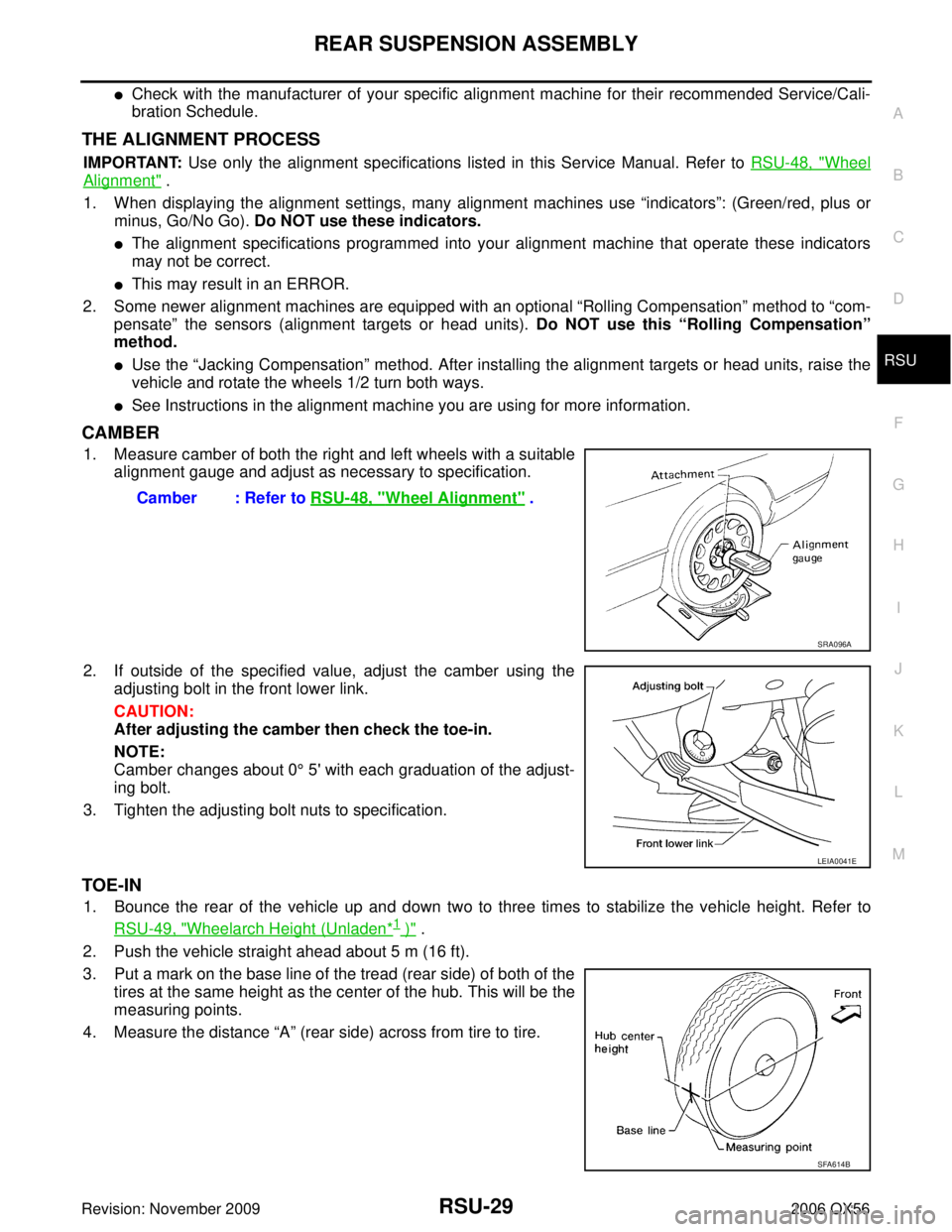
1. Measure camber of both the right and left wheels with a suitable alignment gauge and adjust as necessary to specification.
2. If outside of the specified value, adjust the camber using the adjusting bolt in the front lower link.
CAUTION:
After adjusting the camber then check the toe-in.
NOTE:
Camber changes about 0 ° 5' with each graduation of the adjust-
ing bolt.
3. Tighten the adjusting bolt nuts to specification.
TOE-IN
1. Bounce the rear of the vehicle up and down two to three times to stabilize the vehicle height. Refer to RSU-49, "
Wheelarch Height (Unladen*1 )" .
2. Push the vehicle straight ahead about 5 m (16 ft).
3. Put a mark on the base line of the tread (rear side) of both of the tires at the same height as the center of the hub. This will be the
measuring points.
4. Measure the distance “A” (rear side) across from tire to tire.
Camber : Refer to
RSU-48, "
Wheel Alignment" .
SRA096A
LEIA0041E
SFA614B
WHEEL AND TIRE ASSEMBLYWT-7
C
DF
G H
I
J
K L
M A
B
WT
Revision: November 2009 2006 QX56
c. If calculated balance weight value exceeds 50 g (1.76 oz), install
two balance weight sheets in line with each other as shown.
CAUTION:
Do not install one balance weight sheet on top of another.
3. Start wheel balancer again.
4. Install drive-in balance weight on inner side of road wheel in the wheel balancer indication position (angle).
CAUTION:
Do not install more than two balance weights.
5. Start wheel balancer. Make sure that inner and outer residual imbalance values are 5 g (0.18 oz) each or below.
�If either residual imbalance value exceeds 5 g (0.18 oz), repeat installation procedures.
Wheel balance (Maximum allowable imbalance):
RotationEES001Q1
NOTE:
Follow the maintenance schedule for tire rotation service intervals. Refer to MA-7, "
PERIODIC MAINTE-
NANCE" .
1. Rotate the tires on each side from front to back as shown. Do not include the spare tire when rotating the tires.
CAUTION:
When installing wheels, tighten them diagonally by dividing
the work two to three times in order to prevent the wheels
from developing any distortion.
2. Adjust the tire pressure to specification. Refer to WT-38, "
Tire" .
3. After the tire rotation, retighten the wheel nuts after the vehicle has been driven for 1,000 km (600 miles), and also after every
wheel and tire have been installed such as after repairing a flat
tire.
Maximum allowable imbalance Dynamic (At rim flange)
5 g (0.18 oz) (one side)
Static 10 g (0.35 oz)
SMA056D
Wheel nut torque : 133 N·m (14 kg-m, 98 ft-lb)
SMA829C
 If towing a trailer, or using a car-top carrier, or driving on rough or muddy roads, change (not just inspect)")
, install
two balance weight sheets in line with eac")