2006 INFINITI QX56 fuel pressure
[x] Cancel search: fuel pressurePage 1133 of 3383

DI-12
COMBINATION METERS
Revision: November 20092006 QX56
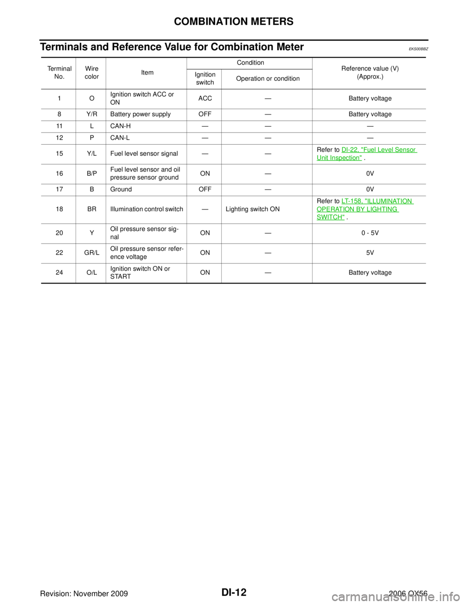
Terminals and Reference Value for Combination MeterEKS00BBZ
Terminal
No. Wire
color Item Condition
Reference value (V)
(Approx.)
Ignition
switch Operation or condition
1O Ignition switch ACC or
ON ACC
— Battery voltage
8 Y/R Battery power supply OFF —Battery voltage
11 L C A N - H —— —
12 P CAN-L —— —
15 Y/L Fuel level sensor signal ——Refer to
DI-22, "
Fuel Level Sensor
Unit Inspection" .
16 B/P Fuel level sensor and oil
pressure sensor ground
ON
— 0V
17 B Ground OFF— 0V
18 BR Illumination control switch —Lighting switch ON Refer to
LT-158, "
ILLUMINATION
OPERATION BY LIGHTING
SWITCH" .
20 Y Oil pressure sensor sig-
nal
ON
— 0 - 5V
22 GR/L Oil pressure sensor refer-
ence voltage ON
— 5V
24 O/L Ignition switch ON or
START ON
— Battery voltage
Page 1135 of 3383

DI-14
COMBINATION METERS
Revision: November 20092006 QX56
Next test requested bulbIlluminates all micro-con-
trolled lamps/LEDs
regardless of SW configu-
ration.
Next test requested D-HI Meter/LCD Illumination.
Next test requested (All segments illuminated) Lights all odometer/trip
meter, fuel, and engine
temperature display seg-
ments.Full daytime brightness all
LCD segments active
Next test requested N-HI Meter/LCD Illumination.
Next test requested (All segments illuminated) Lights all odometer/trip
meter, fuel, and engine
temperature display seg-
ments.Full nighttime brightness all
LCD segments active
Next test requested N-LO Meter/LCD Illumination.
Next test requested (All segments illuminated) Lights all odometer/trip
meter, fuel, and engine
temperature display seg-
ments.Min. nighttime brightness all
LCD segments active
Next test requested dS XX Current dimming step. 1-21
Next test requested EE XX, FAIL Hex EE level. If EE
checksum fault exists,
display alternates
between "EE XX" and
"FAIL".
Next test requested dtXXXX Hex coding of final manu-
facturing test date.
Next test requested GAGE Performs sweep of all
gauges, then displays
present gauge values.
Performs checksum tests
on ROM and EE.Gauges sweep within 10 sec-
onds
Next test requested FFXXXX Displays 16-bit fuel flow
constant "Q" in tenths of
cc/min in Hex format.$0000 - $FFFF
Next test requested tF Displays 16-bit tire factor
"A" in hundredths in Hex
format.$0000 - $FFFF
Next test requested oP Current oil pressure value
in A/D counts in hex for-
mat.
$00 - $FF
Next test requested ot1XX Displays oil pressure tell-
tale "on" threshold in A/D
counts in Hex format.$00 - $FF
Next test requested ot0XX Displays oil pressure tell-
tale "off" threshold in A/D
counts in Hex format.$00 - $FF
Next test requested XXXXX Raw uncompensated
english speed value in
hundredths of MPH.
Speedometer indicates
present speed.Will display "-----" if message is
not received. Will display
"99999" if data received is
invalid
Next test requested XXXXX Raw uncompensated
metric speed value in
hundredths of KPH.
Speedometer indicates
present speed.Will display "-----" if message is
not received. Will display
"99999" if data received is
invalid
Event Odometer Display Description of Test/Data Notes:
Page 1140 of 3383

COMBINATION METERSDI-19
C
DE
F
G H
I
J
L
M A
B
DI
Revision: November 2009 2006 QX56
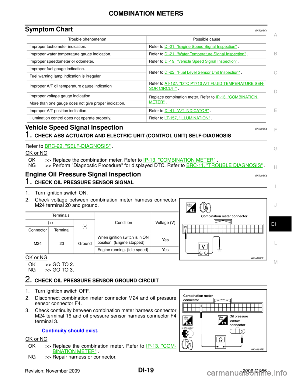
Symptom ChartEKS00BC4
Vehicle Speed Signal InspectionEKS00BC5
1. CHECK ABS ACTUATOR AND ELECTRIC UNIT (CONTROL UNIT) SELF-DIAGNOSIS
Refer to BRC-29, "
SELF-DIAGNOSIS" .
OK or NG
OK >> Replace the combination meter. Refer to IP-13, "COMBINATION METER" .
NG >> Perform "Diagnostic Procedure" for displayed DTC. Refer to BRC-11, "
TROUBLE DIAGNOSIS" .
Engine Oil Pressure Signal Inspection EKS00BC6
1. CHECK OIL PRESSURE SENSOR SIGNAL
1. Turn ignition switch ON.
2. Check voltage between combination meter harness connector M24 terminal 20 and ground.
OK or NG
OK >> GO TO 2.
NG >> GO TO 3.
2. CHECK OIL PRESSURE SENSOR GROUND CIRCUIT
1. Turn ignition switch OFF.
2. Disconnect combination meter connector M24 and oil pressure sensor connector F4.
3. Check continuity between combination meter harness connector M24 terminal 16 and oil pressure sensor harness connector F4
terminal 3.
OK or NG
OK >> Replace the combination meter. Refer to IP-13, "COM-
BINATION METER" .
NG >> Repair harness or connector.
Trouble phenomenon Possible cause
Improper tachometer indication. Refer to DI-21, "
Engine Speed Signal Inspection" .
Improper water temperature gauge indication. Refer to DI-21, "
Water Temperature Signal Inspection" .
Improper speedometer or odometer. Refer to DI-19, "
Vehicle Speed Signal Inspection" .
Improper fuel gauge indication. Refer to DI-22, "
Fuel Level Sensor Unit Inspection" .
Fuel warning lamp indication is irregular.
Improper A/T oil temperature gauge indication Refer to
AT-127, "
DTC P1710 A/T FLUID TEMPERATURE SEN-
SOR CIRCUIT" .
Improper voltage gauge indication Replace combination meter. Refer to IP-13, "
COMBINATION
METER" .
More than one gauge does not give proper indication.
Improper A/T position indication. Refer to DI-41, "
A/T INDICATOR" .
Illumination control does not operate properly. Refer to LT-157, "
ILLUMINATION" .
Terminals
Condition Voltage (V)
(+)
(– )
Connector Terminal
M24 20 Ground When ignition switch is in ON
position. (Engine stopped)
Ye s
Engine running. (Idle speed) Yes
WKIA1833E
Continuity should exist.
WKIA1837E
Page 1212 of 3383

EC-1
ENGINE CONTROL SYSTEM
B ENGINE
CONTENTS
C
DE
F
G H
I
J
K L
M
SECTION
A
EC
Revision: November 2009 2006 QX56
INDEX FOR DTC ...................................................
..... 8
DTC No. Index .................................................... ..... 8
Alphabetical Index ............................................... ... 12
PRECAUTIONS ..................................................... ... 16
Precautions for Supplemental Restraint System
(SRS) “AIR BAG” and “SEAT BELT PRE-TEN-
SIONER” ............................................................. ... 16
On Board Diagnostic (OBD) System of Engine and
A/T ....................................................................... ... 16
Precaution ........................................................... ... 16
PREPARATION ...................................................... ... 20
Special Service Tools .......................................... ... 20
Commercial Service Tools ................................... ... 22
ENGINE CONTROL SYSTEM ............................... ... 23
System Diagram .................................................. ... 23
Multiport Fuel Injection (MFI) System ................. ... 24
Electronic Ignition (EI) System ............................ ... 26
Fuel Cut Control (at No Load and High Engine
Speed) ................................................................. ... 27
AIR CONDITIONING CUT CONTROL .................. ... 28
Input/Output Signal Chart .................................... ... 28
System Description ............................................. ... 28
AUTOMATIC SPEED CONTROL DEVICE (ASCD) ... 29
System Description ............................................. ... 29
Component Description ....................................... ... 30
CAN COMMUNICATION ....................................... ... 31
System Description ............................................. ... 31
EVAPORATIVE EMISSION SYSTEM .................... ... 32
Description .......................................................... ... 32
Component Inspection ........................................ ... 35
Removal and Installation ..................................... ... 36
How to Detect Fuel Vapor Leakage .................... ... 37
ON BOARD REFUELING VAPOR RECOVERY
(ORVR) ................................................................... ... 39
System Description ............................................. ... 39
Diagnostic Procedure .......................................... ... 40
Component Inspection ........................................ ... 43
POSITIVE CRANKCASE VENTILATION .............. ... 45
Description .......................................................... ... 45
Component Inspection ........................................ ... 45IVIS (INFINITI VEHICLE IMMOBILIZER SYSTEM-
NATS) .....................................................................
... 47
Description ........................................................... ... 47
ON BOARD DIAGNOSTIC (OBD) SYSTEM ......... ... 48
Introduction .......................................................... ... 48
Two Trip Detection Logic ..................................... ... 48
Emission-related Diagnostic Information ............. ... 49
Malfunction Indicator Lamp (MIL) ........................ ... 63
OBD System Operation Chart ............................. ... 65
BASIC SERVICE PROCEDURE ............................ ... 71
Basic Inspection ..................................................... 71
Idle Speed and Ignition Timing Check ................. ... 76
VIN Registration ..................................................... 77
Accelerator Pedal Released Position Learning ... ... 78
Throttle Valve Closed Position Learning .............. ... 78
Idle Air Volume Learning ..................................... ... 78
Fuel Pressure Check .............................................. 80
TROUBLE DIAGNOSIS ......................................... ... 83
Trouble Diagnosis Introduction ............................ ... 83
DTC Inspection Priority Chart .............................. ... 89
Fail-safe Chart ..................................................... ... 91
Symptom Matrix Chart ......................................... ... 92
Engine Control Component Parts Location ......... ... 96
Vacuum Hose Drawing ........................................ .102
Circuit Diagram .................................................... .103
ECM Harness Connector Terminal Layout .......... .105
ECM Terminals and Reference Value .................. .105
CONSULT-II Function (ENGINE) ......................... .114
Generic Scan Tool (GST) Function ...................... .127
CONSULT-II Reference Value in Data Monitor .... .129
Major Sensor Reference Graph in Data Monitor
Mode .................................................................... .132
TROUBLE DIAGNOSIS - SPECIFICATION VALUE .134
Description ........................................................... .134
Testing Condition ................................................. .134
Inspection Procedure ........................................... .134
Diagnostic Procedure .......................................... .135
TROUBLE DIAGNOSIS FOR INTERMITTENT INCI-
DENT ...................................................................... .144
Page 1215 of 3383

EC-4Revision: November 20092006 QX56
DTC P0340 CMP SENSOR (PHASE) ....................
.347
Component Description ....................................... .347
On Board Diagnosis Logic ................................... .347
DTC Confirmation Procedure .............................. .347
Wiring Diagram .................................................... .349
Diagnostic Procedure .......................................... .350
Component Inspection ......................................... .353
Removal and Installation ..................................... .353
DTC P0420, P0430 THREE WAY CATALYST FUNC-
TION ....................................................................... .354
On Board Diagnosis Logic ................................... .354
DTC Confirmation Procedure .............................. .354
Overall Function Check ....................................... .355
Diagnostic Procedure .......................................... .356
DTC P0441 EVAP CONTROL SYSTEM ................ .360
System Description .............................................. .360
On Board Diagnosis Logic ................................... .360
DTC Confirmation Procedure .............................. .360
Overall Function Check ....................................... .361
Diagnostic Procedure .......................................... .362
DTC P0442 EVAP CONTROL SYSTEM ................ .365
On Board Diagnosis Logic ................................... .365
DTC Confirmation Procedure .............................. .366
Diagnostic Procedure .......................................... .367
DTC P0443 EVAP CANISTER PURGE VOLUME
CONTROL SOLENOID VALVE .............................. .373
Description ........................................................... .373
CONSULT-II Reference Value in Data Monitor Mode .373
On Board Diagnosis Logic ................................... .374
DTC Confirmation Procedure .............................. .374
Wiring Diagram .................................................... .375
Diagnostic Procedure .......................................... .377
Component Inspection ......................................... .380
Removal and Installation ..................................... .380
DTC P0444, P0445 EVAP CANISTER PURGE VOL-
UME CONTROL SOLENOID VALVE ..................... .381
Description ........................................................... .381
CONSULT-II Reference Value in Data Monitor Mode .381
On Board Diagnosis Logic ................................... .382
DTC Confirmation Procedure .............................. .382
Wiring Diagram .................................................... .383
Diagnostic Procedure .......................................... .385
Component Inspection ......................................... .386
Removal and Installation ..................................... .387
DTC P0447 EVAP CANISTER VENT CONTROL
VALVE .................................................................... .388
Component Description ....................................... .388
CONSULT-II Reference Value in Data Monitor Mode .388
On Board Diagnosis Logic ................................... .388
DTC Confirmation Procedure .............................. .389
Wiring Diagram .................................................... .390
Diagnostic Procedure .......................................... .391
Component Inspection ......................................... .393
DTC P0448 EVAP CANISTER VENT CONTROL
VALVE .................................................................... .395
Component Description ....................................... .395CONSULT-II Reference Value in Data Monitor Mode
.395
On Board Diagnosis Logic ................................... .395
DTC Confirmation Procedure ............................... .396
Wiring Diagram .................................................... .397
Diagnostic Procedure ........................................... .398
Component Inspection ......................................... .400
DTC P0451 EVAP CONTROL SYSTEM PRESSURE
SENSOR ................................................................. .402
Component Description ....................................... .402
CONSULT-II Reference Value in Data Monitor Mode .402
On Board Diagnosis Logic ................................... .402
DTC Confirmation Procedure ............................... .403
Diagnostic Procedure ........................................... .403
Component Inspection ......................................... .404
DTC P0452 EVAP CONTROL SYSTEM PRESSURE
SENSOR ................................................................. .405
Component Description ....................................... .405
CONSULT-II Reference Value in Data Monitor Mode .405
On Board Diagnosis Logic ................................... .405
DTC Confirmation Procedure ............................... .406
Wiring Diagram .................................................... .407
Diagnostic Procedure ........................................... .408
Component Inspection ......................................... .410
DTC P0453 EVAP CONTROL SYSTEM PRESSURE
SENSOR ................................................................. .411
Component Description ....................................... .411
CONSULT-II Reference Value in Data Monitor Mode .411
On Board Diagnosis Logic ................................... .411
DTC Confirmation Procedure ............................... .412
Wiring Diagram .................................................... .413
Diagnostic Procedure ........................................... .414
Component Inspection ......................................... .418
DTC P0455 EVAP CONTROL SYSTEM ................ .419
On Board Diagnosis Logic ................................... .419
DTC Confirmation Procedure ............................... .420
Diagnostic Procedure ........................................... .421
DTC P0456 EVAP CONTROL SYSTEM ................ .427
On Board Diagnosis Logic ................................... .427
DTC Confirmation Procedure ............................... .428
Overall Function Check ........................................ .429
Diagnostic Procedure ........................................... .430
DTC P0460 FUEL LEVEL SENSOR ...................... .436
Component Description ....................................... .436
On Board Diagnosis Logic ................................... .436
DTC Confirmation Procedure ............................... .436
Diagnostic Procedure ........................................... .437
Removal and Installation ...................................... .437
DTC P0461 FUEL LEVEL SENSOR ...................... .438
Component Description ....................................... .438
On Board Diagnosis Logic ................................... .438
Overall Function Check ........................................ .438
Diagnostic Procedure ........................................... .439
Removal and Installation ...................................... .439
DTC P0462, P0463 FUEL LEVEL SENSOR CIR-
CUIT ........................................................................ .440
Page 1218 of 3383

EC-7
C
DE
F
G H
I
J
K L
M
EC A
Revision: November 2009 2006 QX56
Diagnostic Procedure ..........................................
. 588
Component Inspection ........................................ . 592
ASCD INDICATOR ................................................ . 593
Component Description ....................................... . 593
CONSULT-II Reference Value in Data Monitor Mode . 593
Wiring Diagram ................................................... . 594
Diagnostic Procedure .......................................... . 595
ELECTRICAL LOAD SIGNAL ............................... . 596
Description .......................................................... . 596
CONSULT-II Reference Value in Data Monitor Mode . 596
Diagnostic Procedure .......................................... . 596
FUEL INJECTOR ................................................... . 598
Component Description ....................................... . 598
CONSULT-II Reference Value in Data Monitor Mode . 598
Wiring Diagram ................................................... . 599
Diagnostic Procedure .......................................... . 600
Component Inspection ........................................ . 603
Removal and Installation ..................................... . 603
FUEL PUMP .......................................................... . 604
Description .......................................................... . 604
CONSULT-II Reference Value in Data Monitor Mode . 604
Wiring Diagram ................................................... . 605
Diagnostic Procedure .......................................... . 606
Component Inspection ........................................ . 609
Removal and Installation ..................................... . 609
ICC BRAKE SWITCH ............................................ . 610
Component Description ....................................... . 610
CONSULT-II Reference Value in Data Monitor Mode .610
Wiring Diagram .................................................... .611
Diagnostic Procedure .......................................... .612
Component Inspection ......................................... .617
IGNITION SIGNAL ................................................. .618
Component Description ....................................... .618
Wiring Diagram .................................................... .619
Diagnostic Procedure .......................................... .624
Component Inspection ......................................... .628
Removal and Installation ..................................... .629
REFRIGERANT PRESSURE SENSOR ................. .630
Component Description ....................................... .630
Wiring Diagram .................................................... .631
Diagnostic Procedure .......................................... .632
Removal and Installation ..................................... .634
MIL AND DATA LINK CONNECTOR ..................... .635
Wiring Diagram .................................................... .635
SERVICE DATA AND SPECIFICATIONS (SDS) ... .637
Fuel Pressure ...................................................... .637
Idle Speed and Ignition Timing ............................ .637
Calculated Load Value ......................................... .637
Mass Air Flow Sensor .......................................... .637
Intake Air Temperature Sensor ............................ .637
Engine Coolant Temperature Sensor .................. .637
A/F Sensor 1 Heater ............................................ .637
Heated Oxygen sensor 2 Heater ......................... .637
Crankshaft Position Sensor (POS) ...................... .637
Camshaft Position Sensor (PHASE) ................... .637
Throttle Control Motor .......................................... .637
Fuel Injector ......................................................... .638
Fuel Pump ........................................................... .638
Page 1231 of 3383

EC-20Revision: November 2009
PREPARATION
2006 QX56
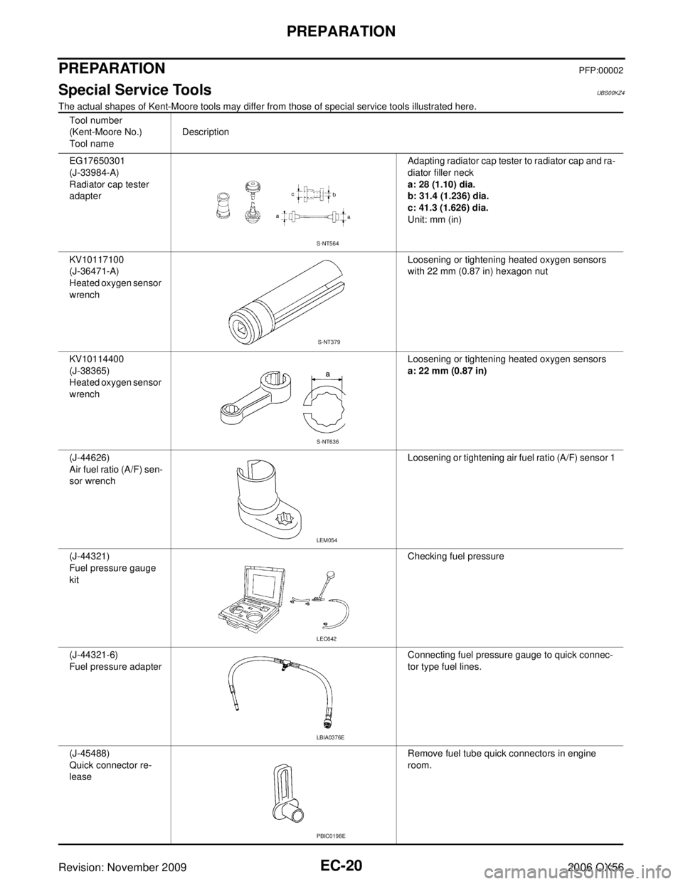
PREPARATIONPFP:00002
Special Service ToolsUBS00KZ4
The actual shapes of Kent-Moore tools may differ from those of special service tools illustrated here.Tool number
(Kent-Moore No.)
Tool name Description
EG17650301
(J-33984-A)
Radiator cap tester
adapter Adapting radiator cap tester to radiator cap and ra-
diator filler neck
a: 28 (1.10) dia.
b: 31.4 (1.236) dia.
c: 41.3 (1.626) dia.
Unit: mm (in)
KV10117100
(J-36471-A)
Heated oxygen sensor
wrench Loosening or tightening heated oxygen sensors
with 22 mm (0.87 in) hexagon nut
KV10114400
(J-38365)
Heated oxygen sensor
wrench Loosening or tightening heated oxygen sensors
a: 22 mm (0.87 in)
(J-44626)
Air fuel ratio (A/F) sen-
sor wrench Loosening or tightening air fuel ratio (A/F) sensor 1
(J-44321)
Fuel pressure gauge
kit Checking fuel pressure
(J-44321-6)
Fuel pressure adapter Connecting fuel pressure gauge to quick connec-
tor type fuel lines.
(J-45488)
Quick connector re-
lease Remove fuel tube quick connectors in engine
room.
S-NT564
S-NT379
S-NT636
LEM054
LEC642
LBIA0376E
PBIC0198E
Page 1233 of 3383

EC-22Revision: November 2009
PREPARATION
2006 QX56
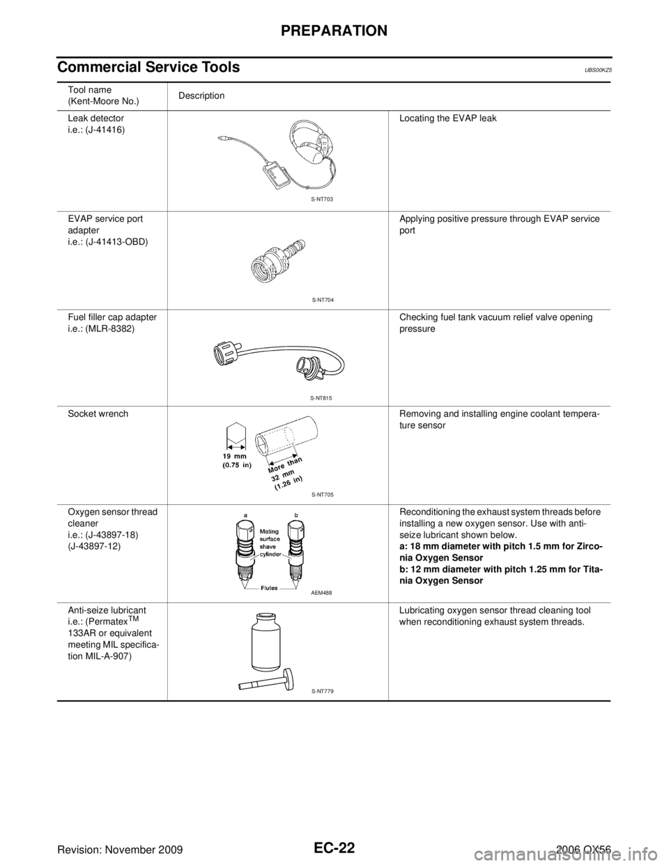
Commercial Service ToolsUBS00KZ5
Tool name
(Kent-Moore No.)Description
Leak detector
i.e.: (J-41416) Locating the EVAP leak
EVAP service port
adapter
i.e.: (J-41413-OBD) Applying positive pressure through EVAP service
port
Fuel filler cap adapter
i.e.: (MLR-8382) Checking fuel tank vacuum relief valve opening
pressure
Socket wrench Removing and installing engine coolant tempera- ture sensor
Oxygen sensor thread
cleaner
i.e.: (J-43897-18)
(J-43897-12) Reconditioning the exhaust system threads before
installing a new oxygen sensor. Use with anti-
seize lubricant shown below.
a: 18 mm diameter with pitch 1.5 mm for Zirco-
nia Oxygen Sensor
b: 12 mm diameter with pitch 1.25 mm for Tita-
nia Oxygen Sensor
Anti-seize lubricant
i.e.: (Permatex
TM
133AR or equivalent
meeting MIL specifica-
tion MIL-A-907) Lubricating oxygen sensor thread cleaning tool
when reconditioning exhaust system threads.
S-NT703
S-NT704
S-NT815
S-NT705
AEM488
S-NT779