Page 3235 of 3383

TF-130
TROUBLE DIAGNOSIS FOR SYMPTOMS
Revision: November 20092006 QX56
Heavy Tight-corner Braking Symptom OccursEDS002HT
SYMPTOM:
Heavy tight-corner braking symptom occurs when vehicle is driven in AUTO mode and steering wheel
is turned fully to either side.
DIAGNOSTIC PROCEDURE
NOTE:
�Light tight-corner braking symptom may occur depending on driving conditions in AUTO mode. This is not
a malfunction.
�Heavy tight-corner braking symptom occurs when vehicle is driven in the following conditions: 4WD shift
switch is "4H" or "4LO", steering wheel is turned fully to either side.
1. CHECK SYSTEM FOR CAN COMMUNICATION LINE
Perform self-diagnosis. Refer to TF-50, "
SELF-DIAGNOSTIC PROCEDURE (WITH CONSULT-II)" .
Is "CAN COMM CIRCUIT [U1000]" displayed?
YES >> Perform trouble diagnosis for CAN communication line. Refer to TF-113, "CAN Communication
Line" .
NO >> GO TO 2.
2. CHECK SYSTEM FOR 4WD SHIFT SWITCH
Perform trouble diagnosis for 4WD shift switch system. Refer to TF-62, "
4WD Shift Switch" .
OK or NG
OK >> GO TO 3.
NG >> Repair or replace damaged parts.
3. CHECK ACCELERATOR PEDAL POSITION SIGNAL CIRCUIT
Perform self diagnosis for ECM. Refer to EC-49, "
Emission-related Diagnostic Information" .
Is any malfunction deteced by self-diagnosis?
YES >> Check the malfunctioning system.
NO >> GO TO 4.
4. CHECK SYSTEM FOR CLUTCH PRESSURE SOLENOID
Perform trouble diagnosis for clutch pressure solenoid system. Refer to TF-105, "
Clutch Pressure Switch" .
OK or NG
OK >> GO TO 5.
NG >> Repair or replace damaged parts.
5. SYMPTOM CHECK
Check again.
OK or NG
OK >> Inspection End.
NG >> GO TO 6.
6. CHECK TRANSFER CONTROL UNIT
Check transfer control unit input/output signal. Refer to TF-35, "
Transfer Control Unit Input/Output Signal Ref-
erence Values" .
OK or NG
OK >> GO TO 7.
NG >> Check transfer control unit pin terminals for damage or loose connection with harness connector. If any items are damaged, repair or replace damaged parts.
Page 3236 of 3383

TROUBLE DIAGNOSIS FOR SYMPTOMSTF-131
CE F
G H
I
J
K L
M A
B
TF
Revision: November 2009 2006 QX56
7. CHECK TRANSFER INNER PARTS
1. Disassemble transfer assembly. Refer to TF-146, "
Disassembly and Assembly" .
2. Check transfer inner parts.
OK or NG
OK >> Inspection End.
NG >> Repair or replace damaged parts.
4WD System Does Not OperateEDS002HU
SYMPTOM:
The vehicle cannot be put into 4WD mode. (Hydraulic system failure)
DIAGNOSTIC PROCEDURE
1. CHECK SYSTEM FOR 4WD SHIFT SWITCH
Perform trouble diagnosis for 4WD shift switch system. Refer to TF-62, "
4WD Shift Switch" .
OK or NG
OK >> GO TO 2.
NG >> Repair or replace damaged parts.
2. CHECK SYSTEM FOR CLUTCH PRESSURE SWITCH
Perform trouble diagnosis for clutch pressure switch system. Refer to TF-105, "
Clutch Pressure Switch" .
OK or NG
OK >> GO TO 3.
NG >> Repair or replace damaged parts.
3. SYMPTOM CHECK
Check again.
OK or NG
OK >> Inspection End.
NG >> GO TO 4.
4. CHECK TRANSFER CONTROL UNIT
Check transfer control unit input/output signal. Refer to TF-35, "
Transfer Control Unit Input/Output Signal Ref-
erence Values" .
OK or NG
OK >> GO TO 5.
NG >> Check transfer control unit pin terminals for damage or loose connection with harness connector. If any items are damaged, repair or replace damaged parts.
5. CHECK TRANSFER INNER PARTS
1. Disassemble transfer assembly. Refer to TF-146, "
Disassembly and Assembly" .
2. Check transfer inner parts.
OK or NG
OK >> Inspection End.
NG >> Repair or replace damaged parts.
Page 3237 of 3383

TF-132
TRANSFER CONTROL UNIT
Revision: November 20092006 QX56
TRANSFER CONTROL UNITPFP:33084
Removal and InstallationEDS002IS
REMOVAL
1. Set transfer state as 2WD when 4WD shift switch is at 2WD, or as AUTO when 4WD shift switch is at
AUTO.
CAUTION:
When removing transfer control unit, transfer state must be at 2WD or AUTO.
2. Turn the ignition switch OFF and disconnect negative battery terminal.
3. Remove the glove box assembly. Refer to IP-14, "
Lower Instrument Panel RH and Glove Box" .
4. Disconnect the two transfer control unit connectors.
5. Remove the transfer control unit bolts.
6. Remove the transfer control unit.
INSTALLATION
Installation is in the reverse order of removal.
�When installing the transfer control unit, tighten bolts to the specified torque.
CAUTION:
�Do not connect harness connector to transfer control unit when 4WD shift switch is at 4LO.
�After the installation, check perform self-diagnosis. Refer to TF-50, "Self-diagnostic Procedure" . If NG,
adjust position between transfer assembly and transfer control unit. Refer to TF-4, "
Precautions for Trans-
fer Assembly and Transfer Control Unit Replacement" .
BDIA0014E
Transfer control unit bolts : 5.1 N·m (0.52 kg-m, 45 in-lb)
Page 3243 of 3383
TF-138
TRANSFER CONTROL DEVICE
Revision: November 20092006 QX56
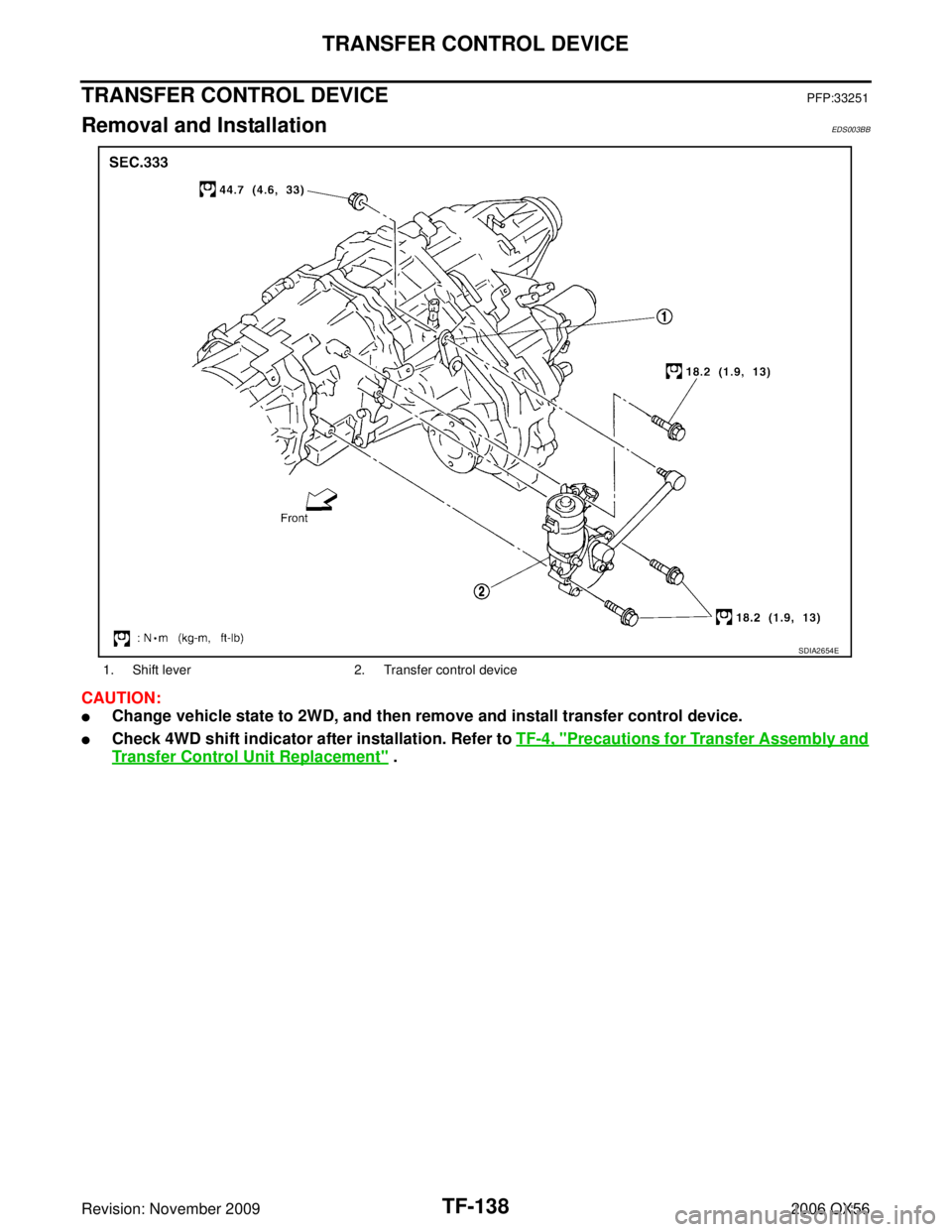
TRANSFER CONTROL DEVICEPFP:33251
Removal and InstallationEDS003BB
CAUTION:
�Change vehicle state to 2WD, and then remove and install transfer control device.
�Check 4WD shift indicator after installation. Refer to TF-4, "Precautions for Transfer Assembly and
Transfer Control Unit Replacement" .
1. Shift lever2. Transfer control device
SDIA2654E
Page 3266 of 3383
TRANSFER ASSEMBLYTF-161
CE F
G H
I
J
K L
M A
B
TF
Revision: November 2009 2006 QX56
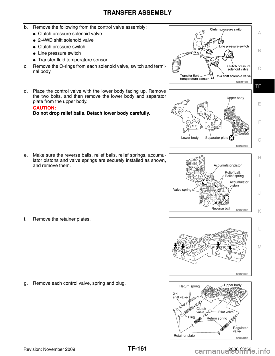
b. Remove the following from the control valve assembly:
�Clutch pressure solenoid valve
�2-4WD shift solenoid valve
�Clutch pressure switch
�Line pressure switch
�Transfer fluid temperature sensor
c. Remove the O-rings from each solenoid valve, switch and termi- nal body.
d. Place the control valve with the lower body facing up. Remove the two bolts, and then remove the lower body and separator
plate from the upper body.
CAUTION:
Do not drop relief balls. Detach lower body carefully.
e. Make sure the reverse balls, relief balls, relief springs, accumu- lator pistons and valve springs are securely installed as shown,
and remove them.
f. Remove the retainer plates.
g. Remove each control valve, spring and plug.
WDIA0199E
SDIA3187E
SDIA2126E
SDIA2127E
SDIA3317E
Page 3270 of 3383

TRANSFER ASSEMBLYTF-165
CE F
G H
I
J
K L
M A
B
TF
Revision: November 2009 2006 QX56
Bearing
�Make sure the bearings roll freely and are free from noise, pit-
ting and cracks.
Main Oil Pump
1. Check the inner and outer circumference, tooth face, and side-
face of the inner and outer gears for damage or abnormal wear.
2. Measure the side clearance between the main oil pump housing edge and the inner and outer gears.
3. Make sure the side clearance is within specification. If the mea- surement is out of specification, replace the inner and outer
gears with new ones as a set. Refer to TF-165, "
Main Oil Pump"
.
Sub-oil Pump
1. Check the inner and outer circumference, tooth face, and side-
face of the inner and outer gears for damage or abnormal wear.
2. Measure the side clearance between the sub oil pump housing edge and the inner and outer gears.
3. Make sure the side clearance is within specification. If the mea- surement is out of specification, replace the inner and outer
gears with new ones as a set. Refer to TF-165, "
Sub-oil Pump" .
Control Valve
�Check resistance between the terminals of the clutch pressure
solenoid valve, 2-4WD shift solenoid valve, clutch pressure
switch, line pressure switch and the transfer fluid temperature
sensor. Refer to TF-90, "
COMPONENT INSPECTION" (clutch
pressure solenoid valve), TF-94, "
COMPONENT INSPECTION"
(2-4WD solenoid valve), TF-107, "COMPONENT INSPECTION"
(clutch pressure switch), TF-110, "COMPONENT INSPECTION"
(line pressure switch) and TF-104, "COMPONENT INSPEC-
TION" (transfer fluid temperature sensor).
SDIA2175E
Specification : 0.015 - 0.035 mm (0.0006 - 0.0014 in)
SDIA2174E
Specification : 0.015 - 0.035 mm (0.0006 - 0.0014 in)
SDIA2173E
WDIA0199E
Page 3274 of 3383

TRANSFER ASSEMBLYTF-169
CE F
G H
I
J
K L
M A
B
TF
Revision: November 2009 2006 QX56
d. Install the reverse balls, relief balls and relief springs, accumula-
tor pistons and valve springs to the upper body.
e. Install the lower body and new separator plate to the upper body.
CAUTION:
Do not reuse separator plate.
f. With the lower body down, tighten the two bolts shown.
g. Apply ATF to the new O-rings, and install them to each solenoid valve, switch and terminal body.
CAUTION:
Do not reuse O-rings.
h. Install the following to the control valve assembly:
�Clutch pressure solenoid valve
�2-4WD shift solenoid valve
�Clutch pressure switch
�Line pressure switch
�Transfer fluid temperature sensor
10. Apply ATF to the new lip seals, and install them to the center case.
CAUTION:
�Do not reuse lip seals.
�There are 2 kinds of lip seals (lip seal of large inner diam-
eter: 5 pieces, lip seal of small inner diameter: 2 pieces).
Confirm their position for installation.
SDIA2126E
WDIA0200E
WDIA0198E
SDIA2123E