Page 1432 of 3383

DTC P0130, P0150 A/F SENSOR 1EC-221
C
DE
F
G H
I
J
K L
M A
EC
Revision: November 2009 2006 QX56
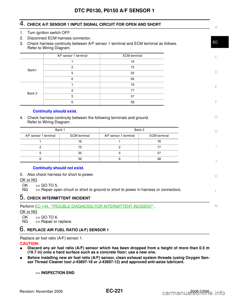
4. CHECK A/F SENSOR 1 INPUT SIGNAL CIRCUIT FOR OPEN AND SHORT
1. Turn ignition switch OFF.
2. Disconnect ECM harness connector.
3. Check harness continuity between A/F sensor 1 terminal and ECM terminal as follows. Refer to Wiring Diagram.
4. Check harness continuity between the following terminals and ground. Refer to Wiring Diagram.
5. Also check harness for short to power.
OK or NG
OK >> GO TO 5.
NG >> Repair open circuit or short to ground or short to power in harness or connectors.
5. CHECK INTERMITTENT INCIDENT
Perform EC-144, "
TROUBLE DIAGNOSIS FOR INTERMITTENT INCIDENT" .
OK or NG
OK >> GO TO 6.
NG >> Repair or replace.
6. REPLACE AIR FUEL RATIO (A/F) SENSOR 1
Replace air fuel ratio (A/F) sensor 1.
CAUTION:
�Discard any air fuel ratio (A/F) sensor which has been dropped from a height of more than 0.5 m
(19.7 in) onto a hard surface such as a concrete floor; use a new one.
�Before installing new air fuel ratio (A/F) sensor, clean exhaust system threads (using Oxygen Sen-
sor Thread Cleaner tool J-43897-18 or J-43897-12) and approved anti-seize lubricant.
>>INSPECTION END
A/F sensor 1 terminal ECM terminal
Bank1 11
6
27 5
53 5
65 6
Bank 2 17
6
27 7
55 7
65 8
Continuity should exist.
Bank 1 Bank 2
A/F sensor 1 terminal ECM terminal A/F sensor 1 terminal ECM terminal 11 617 6
27 527 7
53 555 7
65 665 8
Continuity should not exist.
Page 1436 of 3383
DTC P0131, P0151 A/F SENSOR 1EC-225
C
DE
F
G H
I
J
K L
M A
EC
Revision: November 2009 2006 QX56
Wiring DiagramUBS00H9J
BANK 1
BBWA2111E
Page 1441 of 3383

EC-230Revision: November 2009
DTC P0131, P0151 A/F SENSOR 1
2006 QX56
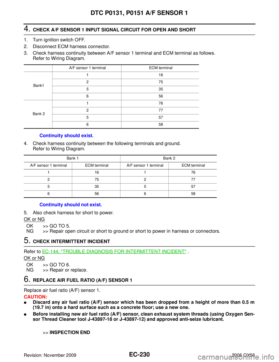
4. CHECK A/F SENSOR 1 INPUT SIGNAL CIRCUIT FOR OPEN AND SHORT
1. Turn ignition switch OFF.
2. Disconnect ECM harness connector.
3. Check harness continuity between A/F sensor 1 terminal and ECM terminal as follows. Refer to Wiring Diagram.
4. Check harness continuity between the following terminals and ground. Refer to Wiring Diagram.
5. Also check harness for short to power.
OK or NG
OK >> GO TO 5.
NG >> Repair open circuit or short to ground or short to power in harness or connectors.
5. CHECK INTERMITTENT INCIDENT
Refer to EC-144, "
TROUBLE DIAGNOSIS FOR INTERMITTENT INCIDENT" .
OK or NG
OK >> GO TO 6.
NG >> Repair or replace.
6. REPLACE AIR FUEL RATIO (A/F) SENSOR 1
Replace air fuel ratio (A/F) sensor 1.
CAUTION:
�Discard any air fuel ratio (A/F) sensor which has been dropped from a height of more than 0.5 m
(19.7 in) onto a hard surface such as a concrete floor; use a new one.
�Before installing new air fuel ratio (A/F) sensor, clean exhaust system threads (using Oxygen Sen-
sor Thread Cleaner tool J-43897-18 or J-43897-12) and approved anti-seize lubricant.
>>INSPECTION END
A/F sensor 1 terminal ECM terminal
Bank1 11
6
27 5
53 5
65 6
Bank 2 17
6
27 7
55 7
65 8
Continuity should exist.
Bank 1 Bank 2
A/F sensor 1 terminal ECM terminal A/F sensor 1 terminal ECM terminal 11 617 6
27 527 7
53 555 7
65 665 8
Continuity should not exist.
Page 1445 of 3383
EC-234Revision: November 2009
DTC P0132, P0152 A/F SENSOR 1
2006 QX56
Wiring DiagramUBS00H9Q
BANK 1
BBWA2111E
Page 1450 of 3383

DTC P0132, P0152 A/F SENSOR 1EC-239
C
DE
F
G H
I
J
K L
M A
EC
Revision: November 2009 2006 QX56
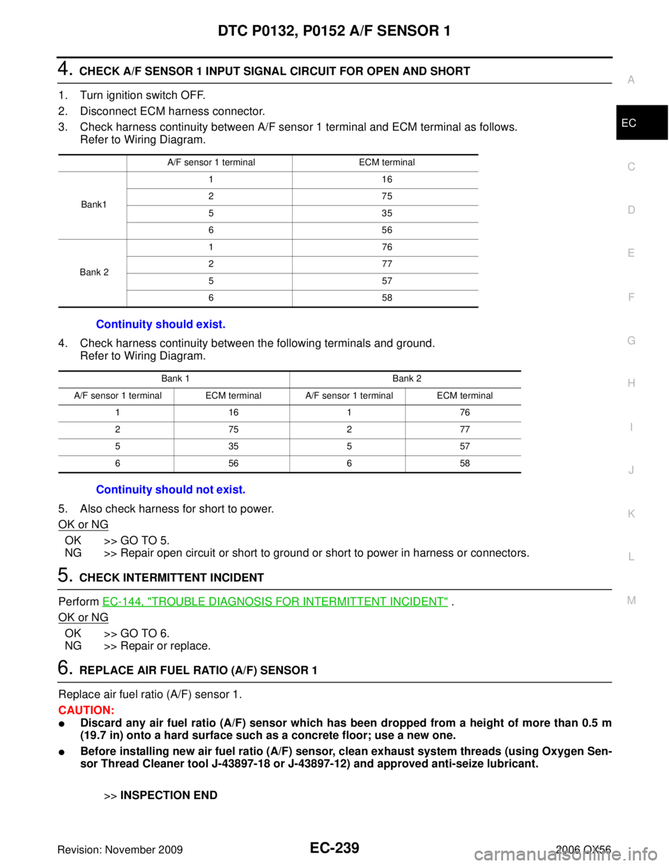
4. CHECK A/F SENSOR 1 INPUT SIGNAL CIRCUIT FOR OPEN AND SHORT
1. Turn ignition switch OFF.
2. Disconnect ECM harness connector.
3. Check harness continuity between A/F sensor 1 terminal and ECM terminal as follows. Refer to Wiring Diagram.
4. Check harness continuity between the following terminals and ground. Refer to Wiring Diagram.
5. Also check harness for short to power.
OK or NG
OK >> GO TO 5.
NG >> Repair open circuit or short to ground or short to power in harness or connectors.
5. CHECK INTERMITTENT INCIDENT
Perform EC-144, "
TROUBLE DIAGNOSIS FOR INTERMITTENT INCIDENT" .
OK or NG
OK >> GO TO 6.
NG >> Repair or replace.
6. REPLACE AIR FUEL RATIO (A/F) SENSOR 1
Replace air fuel ratio (A/F) sensor 1.
CAUTION:
�Discard any air fuel ratio (A/F) sensor which has been dropped from a height of more than 0.5 m
(19.7 in) onto a hard surface such as a concrete floor; use a new one.
�Before installing new air fuel ratio (A/F) sensor, clean exhaust system threads (using Oxygen Sen-
sor Thread Cleaner tool J-43897-18 or J-43897-12) and approved anti-seize lubricant.
>>INSPECTION END
A/F sensor 1 terminal ECM terminal
Bank1 11
6
27 5
53 5
65 6
Bank 2 17
6
27 7
55 7
65 8
Continuity should exist.
Bank 1 Bank 2
A/F sensor 1 terminal ECM terminal A/F sensor 1 terminal ECM terminal 11 617 6
27 527 7
53 555 7
65 665 8
Continuity should not exist.
Page 1455 of 3383
EC-244Revision: November 2009
DTC P0133, P0153 A/F SENSOR 1
2006 QX56
Wiring DiagramUBS00N6V
BANK 1
BBWA2111E
Page 1462 of 3383

DTC P0133, P0153 A/F SENSOR 1EC-251
C
DE
F
G H
I
J
K L
M A
EC
Revision: November 2009 2006 QX56
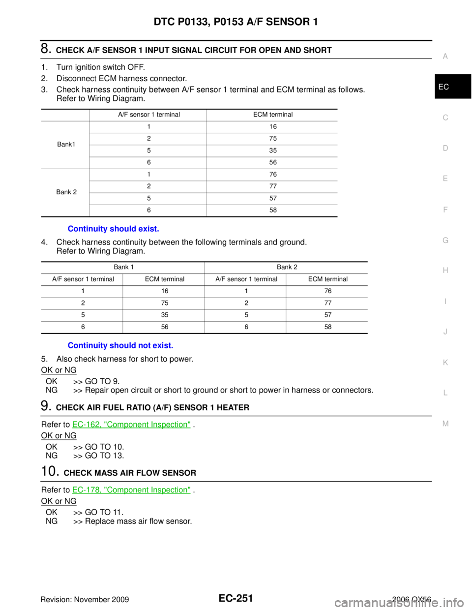
8. CHECK A/F SENSOR 1 INPUT SIGNAL CIRCUIT FOR OPEN AND SHORT
1. Turn ignition switch OFF.
2. Disconnect ECM harness connector.
3. Check harness continuity between A/F sensor 1 terminal and ECM terminal as follows. Refer to Wiring Diagram.
4. Check harness continuity between the following terminals and ground. Refer to Wiring Diagram.
5. Also check harness for short to power.
OK or NG
OK >> GO TO 9.
NG >> Repair open circuit or short to ground or short to power in harness or connectors.
9. CHECK AIR FUEL RATIO (A/F) SENSOR 1 HEATER
Refer to EC-162, "
Component Inspection" .
OK or NG
OK >> GO TO 10.
NG >> GO TO 13.
10. CHECK MASS AIR FLOW SENSOR
Refer to EC-178, "
Component Inspection" .
OK or NG
OK >> GO TO 11.
NG >> Replace mass air flow sensor.
A/F sensor 1 terminal ECM terminal
Bank1 11
6
27 5
53 5
65 6
Bank 2 17
6
27 7
55 7
65 8
Continuity should exist.
Bank 1 Bank 2
A/F sensor 1 terminal ECM terminal A/F sensor 1 terminal ECM terminal 11 617 6
27 527 7
53 555 7
65 665 8
Continuity should not exist.
Page 1467 of 3383
EC-256Revision: November 2009
DTC P0137, P0157 HO2S2
2006 QX56
Wiring DiagramUBS00H8G
BANK 1
BBWA1678E