2006 INFINITI M35 check engine
[x] Cancel search: check enginePage 3352 of 5621
EX-1
EXHAUST SYSTEM
B ENGINE
CONTENTS
C
D
E
F
G
H
I
J
K
L
M
SECTION EX
A
EX
Revision: 2006 January2006 M35/M45
EXHAUST SYSTEM
PREPARATION ........................................................... 2
Special Service Tools ............................................... 2
Commercial Service Tools ........................................ 2
EXHAUST SYSTEM ................................................... 3
Checking Exhaust System ....................................... 3
Components ............................................................. 4
Removal and Installation .......................................... 5
REMOVAL ........................................................
..... 5INSTALLATION ..................................................... 5
INSPECTION AFTER INSTALLATION .................. 5
Components ............................................................. 6
Removal and installation .......................................... 7
REMOVAL ........................................................
..... 7
INSTALLATION ..................................................... 7
INSPECTION AFTER INSTALLATION .................. 7
Page 3356 of 5621
EXHAUST SYSTEM
EX-5
C
D
E
F
G
H
I
J
K
L
MA
EX
Revision: 2006 January2006 M35/M45
Removal and InstallationNBS005RL
CAUTION:
Be sure to use genuine exhaust system parts or equivalents which are specially designed for heat
resistance, corrosion resistance, and shape.
Perform the operation with the exhaust system fully cooled down because the system will be hot
just after engine stops.
Be careful not to cut your hand on the heat insulator edge.
REMOVAL
Disconnect each joint and mounting using power tool.
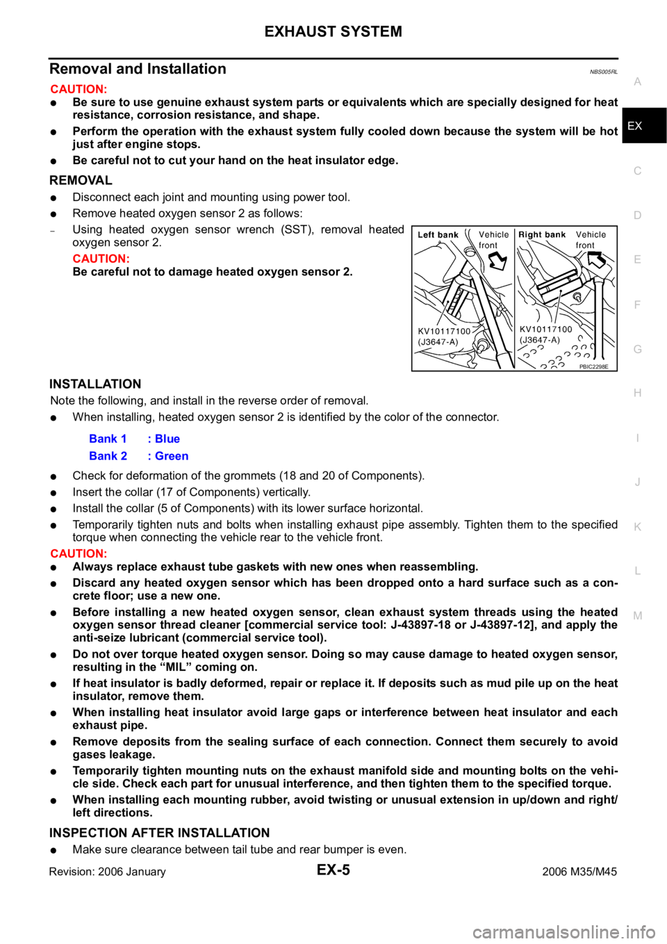
Remove heated oxygen sensor 2 as follows:
–Using heated oxygen sensor wrench (SST), removal heated
oxygen sensor 2.
CAUTION:
Be careful not to damage heated oxygen sensor 2.
INSTALLATION
Note the following, and install in the reverse order of removal.
When installing, heated oxygen sensor 2 is identified by the color of the connector.
Check for deformation of the grommets (18 and 20 of Components).
Insert the collar (17 of Components) vertically.
Install the collar (5 of Components) with its lower surface horizontal.
Temporarily tighten nuts and bolts when installing exhaust pipe assembly. Tighten them to the specified
torque when connecting the vehicle rear to the vehicle front.
CAUTION:
Always replace exhaust tube gaskets with new ones when reassembling.
Discard any heated oxygen sensor which has been dropped onto a hard surface such as a con-
crete floor; use a new one.
Before installing a new heated oxygen sensor, clean exhaust system threads using the heated
oxygen sensor thread cleaner [commercial service tool: J-43897-18 or J-43897-12], and apply the
anti-seize lubricant (commercial service tool).
Do not over torque heated oxygen sensor. Doing so may cause damage to heated oxygen sensor,
resulting in the “MIL” coming on.
If heat insulator is badly deformed, repair or replace it. If deposits such as mud pile up on the heat
insulator, remove them.
When installing heat insulator avoid large gaps or interference between heat insulator and each
exhaust pipe.
Remove deposits from the sealing surface of each connection. Connect them securely to avoid
gases leakage.
Temporarily tighten mounting nuts on the exhaust manifold side and mounting bolts on the vehi-
cle side. Check each part for unusual interference, and then tighten them to the specified torque.
When installing each mounting rubber, avoid twisting or unusual extension in up/down and right/
left directions.
INSPECTION AFTER INSTALLATION
Make sure clearance between tail tube and rear bumper is even.
PBIC2298E
Bank 1 : Blue
Bank 2 : Green
Page 3357 of 5621
EX-6
EXHAUST SYSTEM
Revision: 2006 January2006 M35/M45
With engine running, check exhaust tube joints for gas leakage and unusual noises.
Check to ensure that mounting brackets and mounting rubbers are installed properly and free from undue
stress. Improper installation could result in excessive noise and vibration.
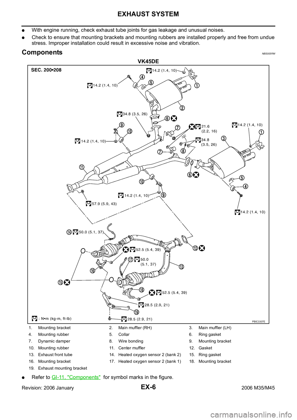
ComponentsNBS005RM
VK45DE
Refer to GI-11, "Components" for symbol marks in the figure.
PBIC3307E
1. Mounting bracket 2. Main muffler (RH) 3. Main muffler (LH)
4. Mounting rubber 5. Collar 6. Ring gasket
7. Dynamic damper 8. Wire bonding 9. Mounting bracket
10. Mounting rubber 11. Center muffler 12. Gasket
13. Exhaust front tube 14. Heated oxygen sensor 2 (bank 2) 15. Ring gasket
16. Mounting bracket 17. Heated oxygen sensor 2 (bank 1) 18. Mounting bracket
19. Exhaust mounting bracket
Page 3358 of 5621
EXHAUST SYSTEM
EX-7
C
D
E
F
G
H
I
J
K
L
MA
EX
Revision: 2006 January2006 M35/M45
Removal and installationNBS005RN
CAUTION:
Be sure to use genuine exhaust system parts or equivalents which are specially designed for heat
resistance, corrosion resistance, and shape.
Perform the operation with the exhaust system fully cooled down because the system will be hot
just after engine stops.
Be careful not to cut your hand on the heat insulator edge.
REMOVAL
Disconnect each joint and mounting using power tool.
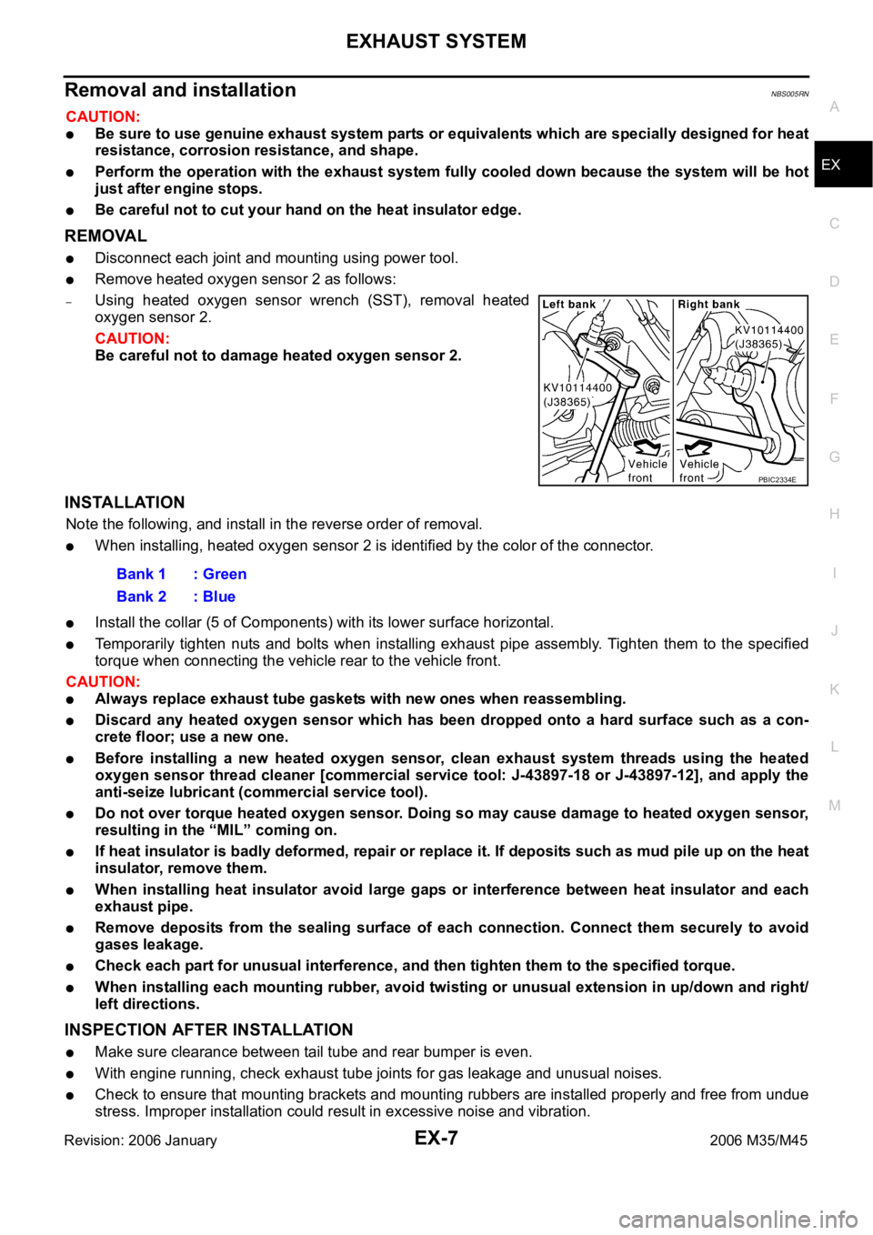
Remove heated oxygen sensor 2 as follows:
–Using heated oxygen sensor wrench (SST), removal heated
oxygen sensor 2.
CAUTION:
Be careful not to damage heated oxygen sensor 2.
INSTALLATION
Note the following, and install in the reverse order of removal.
When installing, heated oxygen sensor 2 is identified by the color of the connector.
Install the collar (5 of Components) with its lower surface horizontal.
Temporarily tighten nuts and bolts when installing exhaust pipe assembly. Tighten them to the specified
torque when connecting the vehicle rear to the vehicle front.
CAUTION:
Always replace exhaust tube gaskets with new ones when reassembling.
Discard any heated oxygen sensor which has been dropped onto a hard surface such as a con-
crete floor; use a new one.
Before installing a new heated oxygen sensor, clean exhaust system threads using the heated
oxygen sensor thread cleaner [commercial service tool: J-43897-18 or J-43897-12], and apply the
anti-seize lubricant (commercial service tool).
Do not over torque heated oxygen sensor. Doing so may cause damage to heated oxygen sensor,
resulting in the “MIL” coming on.
If heat insulator is badly deformed, repair or replace it. If deposits such as mud pile up on the heat
insulator, remove them.
When installing heat insulator avoid large gaps or interference between heat insulator and each
exhaust pipe.
Remove deposits from the sealing surface of each connection. Connect them securely to avoid
gases leakage.
Check each part for unusual interference, and then tighten them to the specified torque.
When installing each mounting rubber, avoid twisting or unusual extension in up/down and right/
left directions.
INSPECTION AFTER INSTALLATION
Make sure clearance between tail tube and rear bumper is even.
With engine running, check exhaust tube joints for gas leakage and unusual noises.
Check to ensure that mounting brackets and mounting rubbers are installed properly and free from undue
stress. Improper installation could result in excessive noise and vibration.
PBIC2334E
Bank 1 : Green
Bank 2 : Blue
Page 3385 of 5621
FFD-8
DIFFERENTIAL GEAR OIL
Revision: 2006 January2006 M35/M45
DIFFERENTIAL GEAR OILPFP:KLD30
Changing Differential Gear OilNDS000EQ
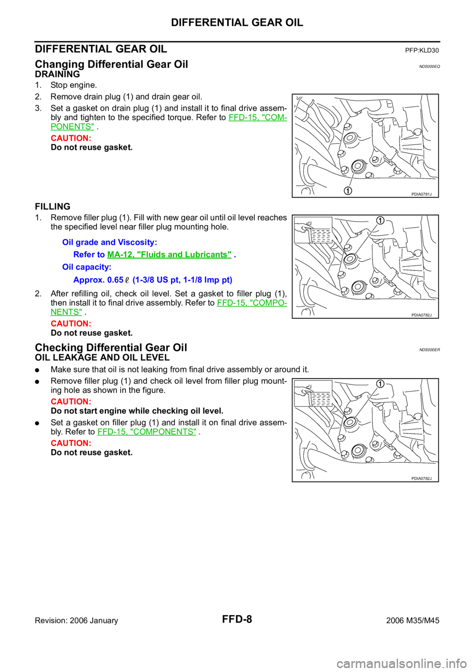
DRAINING
1. Stop engine.
2. Remove drain plug (1) and drain gear oil.
3. Set a gasket on drain plug (1) and install it to final drive assem-
bly and tighten to the specified torque. Refer to FFD-15, "
COM-
PONENTS" .
CAUTION:
Do not reuse gasket.
FILLING
1. Remove filler plug (1). Fill with new gear oil until oil level reaches
the specified level near filler plug mounting hole.
2. After refilling oil, check oil level. Set a gasket to filler plug (1),
then install it to final drive assembly. Refer to FFD-15, "
COMPO-
NENTS" .
CAUTION:
Do not reuse gasket.
Checking Differential Gear OilNDS000ER
OIL LEAKAGE AND OIL LEVEL
Make sure that oil is not leaking from final drive assembly or around it.
Remove filler plug (1) and check oil level from filler plug mount-
ing hole as shown in the figure.
CAUTION:
Do not start engine while checking oil level.
Set a gasket on filler plug (1) and install it on final drive assem-
bly. Refer to FFD-15, "
COMPONENTS" .
CAUTION:
Do not reuse gasket.
PDIA0781J
Oil grade and Viscosity:
Refer to MA-12, "
Fluids and Lubricants" .
Oil capacity:
Approx. 0.65 (1-3/8 US pt, 1-1/8 Imp pt)
PDIA0782J
PDIA0782J
Page 3388 of 5621
SIDE OIL SEAL
FFD-11
C
E
F
G
H
I
J
K
L
MA
B
FFD
Revision: 2006 January2006 M35/M45
SIDE OIL SEALPFP:33142
Removal and InstallationNDS000ET
NOTE:
Left side oil seal is attached to engine assembly. Replace it after removing front final drive assembly
from vehicle.
REMOVAL
Right Side:
1. Remove the front drive shaft. Refer to FAX-11, "Removal and Installation" .
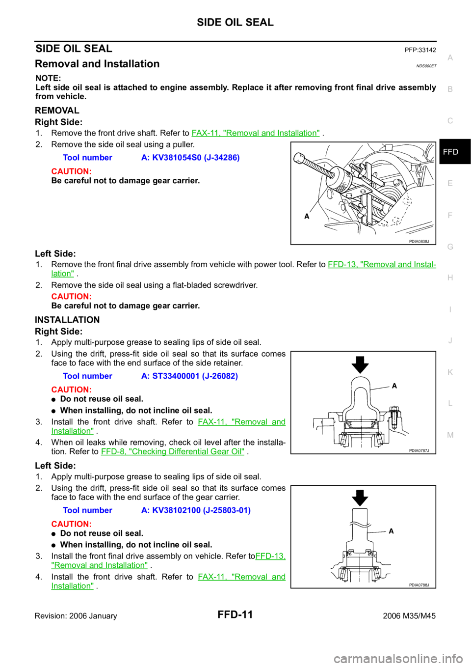
2. Remove the side oil seal using a puller.
CAUTION:
Be careful not to damage gear carrier.
Left Side:
1. Remove the front final drive assembly from vehicle with power tool. Refer to FFD-13, "Removal and Instal-
lation" .
2. Remove the side oil seal using a flat-bladed screwdriver.
CAUTION:
Be careful not to damage gear carrier.
INSTALLATION
Right Side:
1. Apply multi-purpose grease to sealing lips of side oil seal.
2. Using the drift, press-fit side oil seal so that its surface comes
face to face with the end surface of the side retainer.
CAUTION:
Do not reuse oil seal.
When installing, do not incline oil seal.
3. Install the front drive shaft. Refer to FAX-11, "
Removal and
Installation" .
4. When oil leaks while removing, check oil level after the installa-
tion. Refer to FFD-8, "
Checking Differential Gear Oil" .
Left Side:
1. Apply multi-purpose grease to sealing lips of side oil seal.
2. Using the drift, press-fit side oil seal so that its surface comes
face to face with the end surface of the gear carrier.
CAUTION:
Do not reuse oil seal.
When installing, do not incline oil seal.
3. Install the front final drive assembly on vehicle. Refer toFFD-13,
"Removal and Installation" .
4. Install the front drive shaft. Refer to FAX-11, "
Removal and
Installation" . Tool number A: KV381054S0 (J-34286)
PDIA0838J
Tool number A: ST33400001 (J-26082)
PDIA0787J
Tool number A: KV38102100 (J-25803-01)
PDIA0788J
Page 3414 of 5621
FL-1
FUEL SYSTEM
B ENGINE
CONTENTS
C
D
E
F
G
H
I
J
K
L
M
SECTION FL
A
FL
Revision: 2006 January2006 M35/M45
FUEL SYSTEM
PREPARATION ........................................................... 2
Commercial Service Tools ........................................ 2
FUEL SYSTEM ........................................................... 3
Checking Fuel Lines ............................................ ..... 3
General Precautions ................................................ 3
FUEL LEVEL SENSOR UNIT, FUEL FILTER AND
FUEL PUMP ASSEMBLY ........................................... 4
Components ............................................................. 4
Removal and Installation .......................................... 4
REMOVAL ........................................................
..... 4
INSTALLATION ..................................................... 6
INSPECTION AFTER INSTALLATION ................. 7Components ............................................................. 8
Disassembly and Assembly ...................................... 8
DISASSEMBLY ..................................................... 8
ASSEMBLY ........................................................... 9
FUEL TANK .............................................................. 10
Components ........................................................... 10
Removal and Installation ........................................ 10
REMOVAL ........................................................
... 10
INSTALLATION ................................................... 11
INSPECTION AFTER INSTALLATION ................ 11
SERVICE DATA AND SPECIFICATIONS (SDS) ...... 13
Standard and Limit .................................................. 13
FUEL TANK ...................................................... ... 13
Page 3416 of 5621
FUEL SYSTEM
FL-3
C
D
E
F
G
H
I
J
K
L
MA
FL
Revision: 2006 January2006 M35/M45
FUEL SYSTEMPFP:17503
Checking Fuel LinesNBS005R8
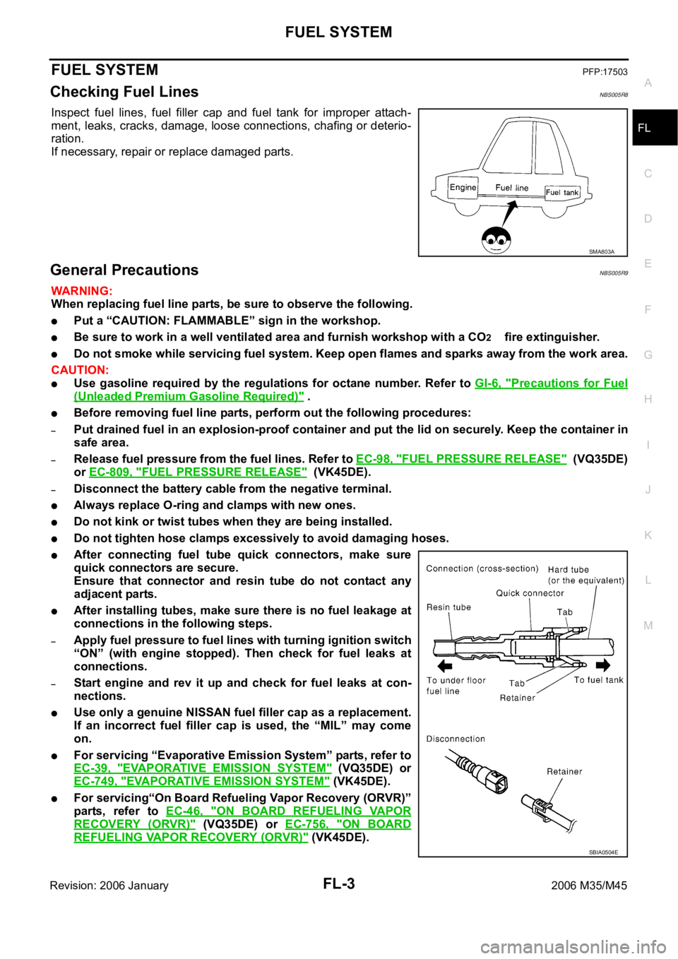
Inspect fuel lines, fuel filler cap and fuel tank for improper attach-
ment, leaks, cracks, damage, loose connections, chafing or deterio-
ration.
If necessary, repair or replace damaged parts.
General PrecautionsNBS005R9
WAR NING :
When replacing fuel line parts, be sure to observe the following.
Put a “CAUTION: FLAMMABLE” sign in the workshop.
Be sure to work in a well ventilated area and furnish workshop with a CO2 fire extinguisher.
Do not smoke while servicing fuel system. Keep open flames and sparks away from the work area.
CAUTION:
Use gasoline required by the regulations for octane number. Refer to GI-6, "Precautions for Fuel
(Unleaded Premium Gasoline Required)" .
Before removing fuel line parts, perform out the following procedures:
–Put drained fuel in an explosion-proof container and put the lid on securely. Keep the container in
safe area.
–Release fuel pressure from the fuel lines. Refer to EC-98, "FUEL PRESSURE RELEASE" (VQ35DE)
or EC-809, "
FUEL PRESSURE RELEASE" (VK45DE).
–Disconnect the battery cable from the negative terminal.
Always replace O-ring and clamps with new ones.
Do not kink or twist tubes when they are being installed.
Do not tighten hose clamps excessively to avoid damaging hoses.
After connecting fuel tube quick connectors, make sure
quick connectors are secure.
Ensure that connector and resin tube do not contact any
adjacent parts.
After installing tubes, make sure there is no fuel leakage at
connections in the following steps.
–Apply fuel pressure to fuel lines with turning ignition switch
“ON” (with engine stopped). Then check for fuel leaks at
connections.
–Start engine and rev it up and check for fuel leaks at con-
nections.
Use only a genuine NISSAN fuel filler cap as a replacement.
If an incorrect fuel filler cap is used, the “MIL” may come
on.
For servicing “Evaporative Emission System” parts, refer to
EC-39, "
EVAPORATIVE EMISSION SYSTEM" (VQ35DE) or
EC-749, "
EVAPORATIVE EMISSION SYSTEM" (VK45DE).
For servicing“On Board Refueling Vapor Recovery (ORVR)”
parts, refer to EC-46, "
ON BOARD REFUELING VAPOR
RECOVERY (ORVR)" (VQ35DE) or EC-756, "ON BOARD
REFUELING VAPOR RECOVERY (ORVR)" (VK45DE).
SMA803A
SBIA0504E