2006 INFINITI M35 wheel torque
[x] Cancel search: wheel torquePage 5462 of 5621
![INFINITI M35 2006 Factory Service Manual TROUBLE DIAGNOSIS
STC-47
[RAS]
C
D
E
F
H
I
J
K
L
MA
B
STC
Revision: 2006 January2006 M35/M45
3. CHECK POWER STEERING SOLENOID VALVE CONNECTOR
Turn ignition switch OFF, disconnect power steering soleno INFINITI M35 2006 Factory Service Manual TROUBLE DIAGNOSIS
STC-47
[RAS]
C
D
E
F
H
I
J
K
L
MA
B
STC
Revision: 2006 January2006 M35/M45
3. CHECK POWER STEERING SOLENOID VALVE CONNECTOR
Turn ignition switch OFF, disconnect power steering soleno](/manual-img/42/57023/w960_57023-5461.png)
TROUBLE DIAGNOSIS
STC-47
[RAS]
C
D
E
F
H
I
J
K
L
MA
B
STC
Revision: 2006 January2006 M35/M45
3. CHECK POWER STEERING SOLENOID VALVE CONNECTOR
Turn ignition switch OFF, disconnect power steering solenoid valve harness connector, and check terminal for
deformation, disconnection, looseness, etc.
OK or NG
OK >> GO TO 4.
NG >> Harness or connector open or shorted. Repair or replace any inoperative parts.
4. CHECK POWER STEERING SOLENOID VALVE POWER SUPPLY CIRCUIT
Check continuity between RAS control unit harness connector B127
and power steering solenoid valve harness connector F25
(VQ35DE), E211 (VK45DE).
OK or NG
OK >> GO TO 5.
NG >> Open or short in harness. Repair or replace any inoper-
ative parts.
5. CHECK POWER STEERING SOLENOID VALVE GROUND CIRCUIT
Check continuity between power steering solenoid valve harness
connector F25 (VQ35DE), E211 (VK45DE) and ground.
OK or NG
OK >> GO TO 6.
NG >> Open or short in harness. Repair or replace any inoper-
ative parts.
6. CHECK POWER STEERING SOLENOID VALVE
Apply voltage power steering solenoid valve connector F25
(VQ35DE), E211 (VK45DE) and then make sure that the operating
sound (clicking sound) is heard.
OK or NG
OK >> Perform steering turning torque inspection. Refer to PS-
10, "CHECKING STEERING WHEEL TURNING
FORCE" .
NG >> Power steering solenoid valve is inoperating. Replace it.
7. CHECK SELF-DIAGNOSIS RESULTS
Perform RAS self-diagnosis.
With CONSULT-II: STC-28, "SELF-DIAG RESULT MODE"
Without CONSULT-II: STC-31, "Diagnosis Procedure with Self-Diagnosis Function (Without CONSULT-
II)"
Are malfunctioning items displayed in self-diagnosis results?
YES >> Repair or replace any malfunctioning items.
NO >> RAS control unit malfunction. Replace it.
RAS C/U Power steering solenoid valve Continuity
Terminal 36 Terminal 1 Yes
SGIA1282E
Terminal 2 – Ground : Continuity exist.
SGIA1283E
Terminal 1 (+) - 2 (-) : Operating sound is heard.
SGIA1284E
Page 5475 of 5621
TF-10
AWD SYSTEM
Revision: 2006 January2006 M35/M45
AWD SYSTEMPFP:41650
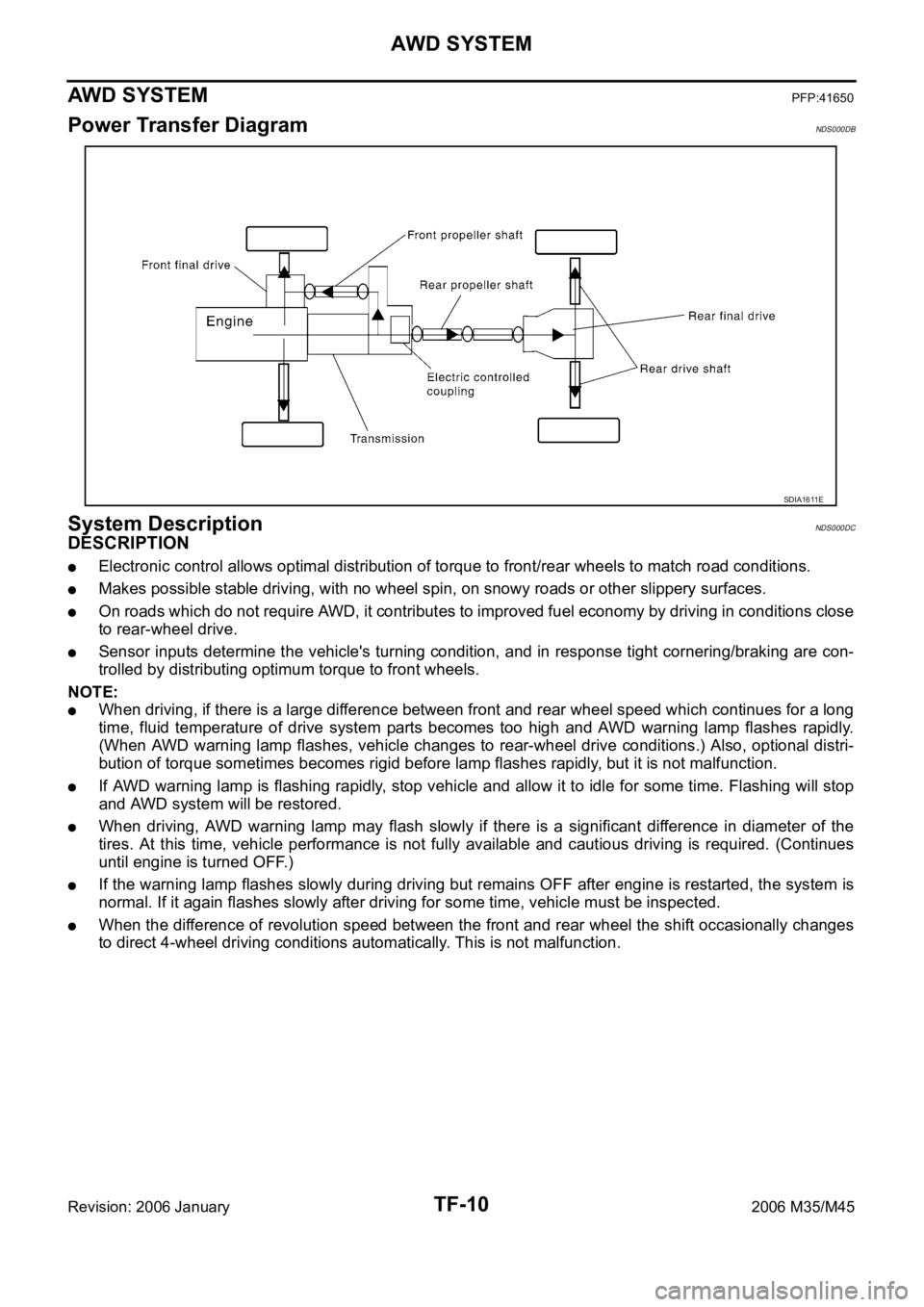
Power Transfer DiagramNDS000DB
System DescriptionNDS000DC
DESCRIPTION
Electronic control allows optimal distribution of torque to front/rear wheels to match road conditions.
Makes possible stable driving, with no wheel spin, on snowy roads or other slippery surfaces.
On roads which do not require AWD, it contributes to improved fuel economy by driving in conditions close
to rear-wheel drive.
Sensor inputs determine the vehicle's turning condition, and in response tight cornering/braking are con-
trolled by distributing optimum torque to front wheels.
NOTE:
When driving, if there is a large difference between front and rear wheel speed which continues for a long
time, fluid temperature of drive system parts becomes too high and AWD warning lamp flashes rapidly.
(When AWD warning lamp flashes, vehicle changes to rear-wheel drive conditions.) Also, optional distri-
bution of torque sometimes becomes rigid before lamp flashes rapidly, but it is not malfunction.
If AWD warning lamp is flashing rapidly, stop vehicle and allow it to idle for some time. Flashing will stop
and AWD system will be restored.
When driving, AWD warning lamp may flash slowly if there is a significant difference in diameter of the
tires. At this time, vehicle performance is not fully available and cautious driving is required. (Continues
until engine is turned OFF.)
If the warning lamp flashes slowly during driving but remains OFF after engine is restarted, the system is
normal. If it again flashes slowly after driving for some time, vehicle must be inspected.
When the difference of revolution speed between the front and rear wheel the shift occasionally changes
to direct 4-wheel driving conditions automatically. This is not malfunction.
SDIA1611E
Page 5476 of 5621
AWD SYSTEM
TF-11
C
E
F
G
H
I
J
K
L
MA
B
TF
Revision: 2006 January2006 M35/M45
ELECTRIC CONTROLLED COUPLING
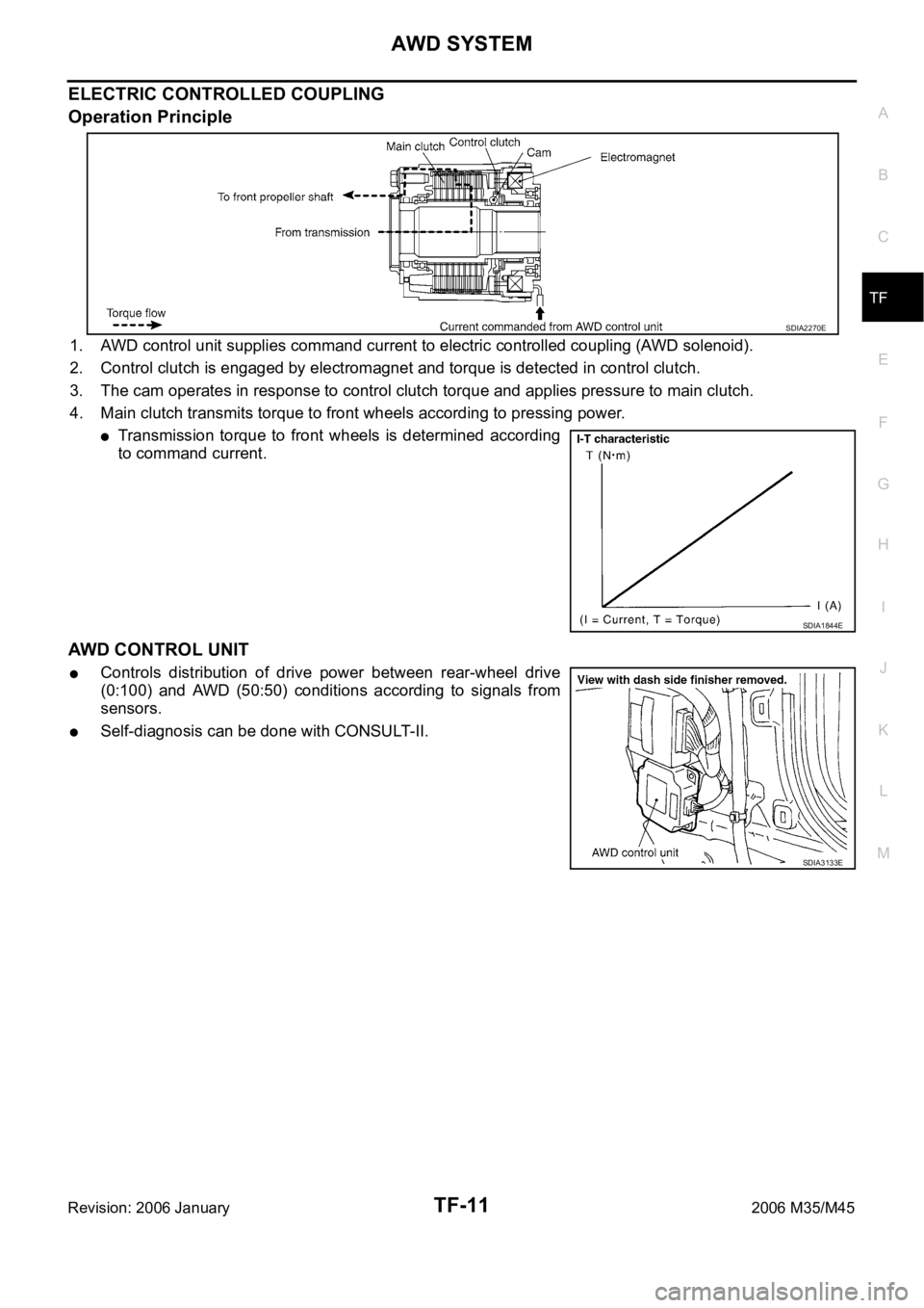
Operation Principle
1. AWD control unit supplies command current to electric controlled coupling (AWD solenoid).
2. Control clutch is engaged by electromagnet and torque is detected in control clutch.
3. The cam operates in response to control clutch torque and applies pressure to main clutch.
4. Main clutch transmits torque to front wheels according to pressing power.
Transmission torque to front wheels is determined according
to command current.
AWD CONTROL UNIT
Controls distribution of drive power between rear-wheel drive
(0:100) and AWD (50:50) conditions according to signals from
sensors.
Self-diagnosis can be done with CONSULT-II.
SDIA2270E
SDIA1844E
SDIA3133E
Page 5477 of 5621
TF-12
AWD SYSTEM
Revision: 2006 January2006 M35/M45
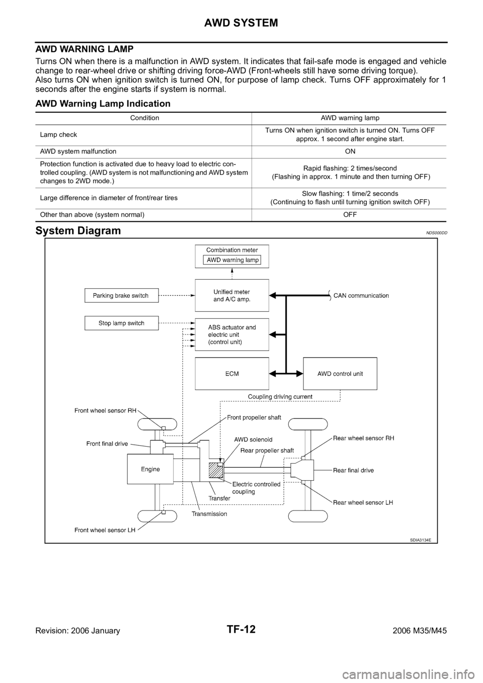
AWD WARNING LAMP
Turns ON when there is a malfunction in AWD system. It indicates that fail-safe mode is engaged and vehicle
change to rear-wheel drive or shifting driving force-AWD (Front-wheels still have some driving torque).
Also turns ON when ignition switch is turned ON, for purpose of lamp check. Turns OFF approximately for 1
seconds after the engine starts if system is normal.
AWD Warning Lamp Indication
System DiagramNDS000DD
Condition AWD warning lamp
Lamp checkTurns ON when ignition switch is turned ON. Turns OFF
approx. 1 second after engine start.
AWD system malfunctionON
Protection function is activated due to heavy load to electric con-
trolled coupling. (AWD system is not malfunctioning and AWD system
changes to 2WD mode.)Rapid flashing: 2 times/second
(Flashing in approx. 1 minute and then turning OFF)
Large difference in diameter of front/rear tiresSlow flashing: 1 time/2 seconds
(Continuing to flash until turning ignition switch OFF)
Other than above (system normal) OFF
SDIA3134E
Page 5479 of 5621
TF-14
TROUBLE DIAGNOSIS
Revision: 2006 January2006 M35/M45
TROUBLE DIAGNOSISPFP:00004
Fail-Safe FunctionNDS000DF
If any malfunction occurs in AWD electrical system, and control unit detects the malfunction, AWD warn-
ing lamp on combination meter turns ON to indicate system malfunction.
When AWD warning lamp is ON, vehicle changes to rear-wheel drive or shifting driving force-AWD (Front-
wheels still have some driving torque).
How to Perform Trouble DiagnosisNDS000DG
BASIC CONCEPT
To perform trouble diagnosis, it is the most important to have understanding about vehicle systems (con-
trol and mechanism) thoroughly.
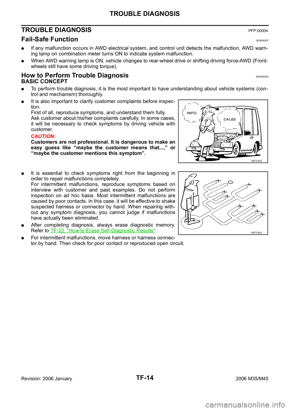
It is also important to clarify customer complaints before inspec-
tion.
First of all, reproduce symptoms, and understand them fully.
Ask customer about his/her complaints carefully. In some cases,
it will be necessary to check symptoms by driving vehicle with
customer.
CAUTION:
Customers are not professional. It is dangerous to make an
easy guess like “maybe the customer means that...,” or
“maybe the customer mentions this symptom”.
It is essential to check symptoms right from the beginning in
order to repair malfunctions completely.
For intermittent malfunctions, reproduce symptoms based on
interview with customer and past examples. Do not perform
inspection on ad hoc basis. Most intermittent malfunctions are
caused by poor contacts. In this case, it will be effective to shake
suspected harness or connector by hand. When repairing with-
out any symptom diagnosis, you cannot judge if malfunctions
have actually been eliminated.
After completing diagnosis, always erase diagnostic memory.
Refer to TF-22, "
How to Erase Self-Diagnostic Results" .
For intermittent malfunctions, move harness or harness connec-
tor by hand. Then check for poor contact or reproduced open circuit.
SEF233G
SEF234G
Page 5485 of 5621
TF-20
TROUBLE DIAGNOSIS
Revision: 2006 January2006 M35/M45
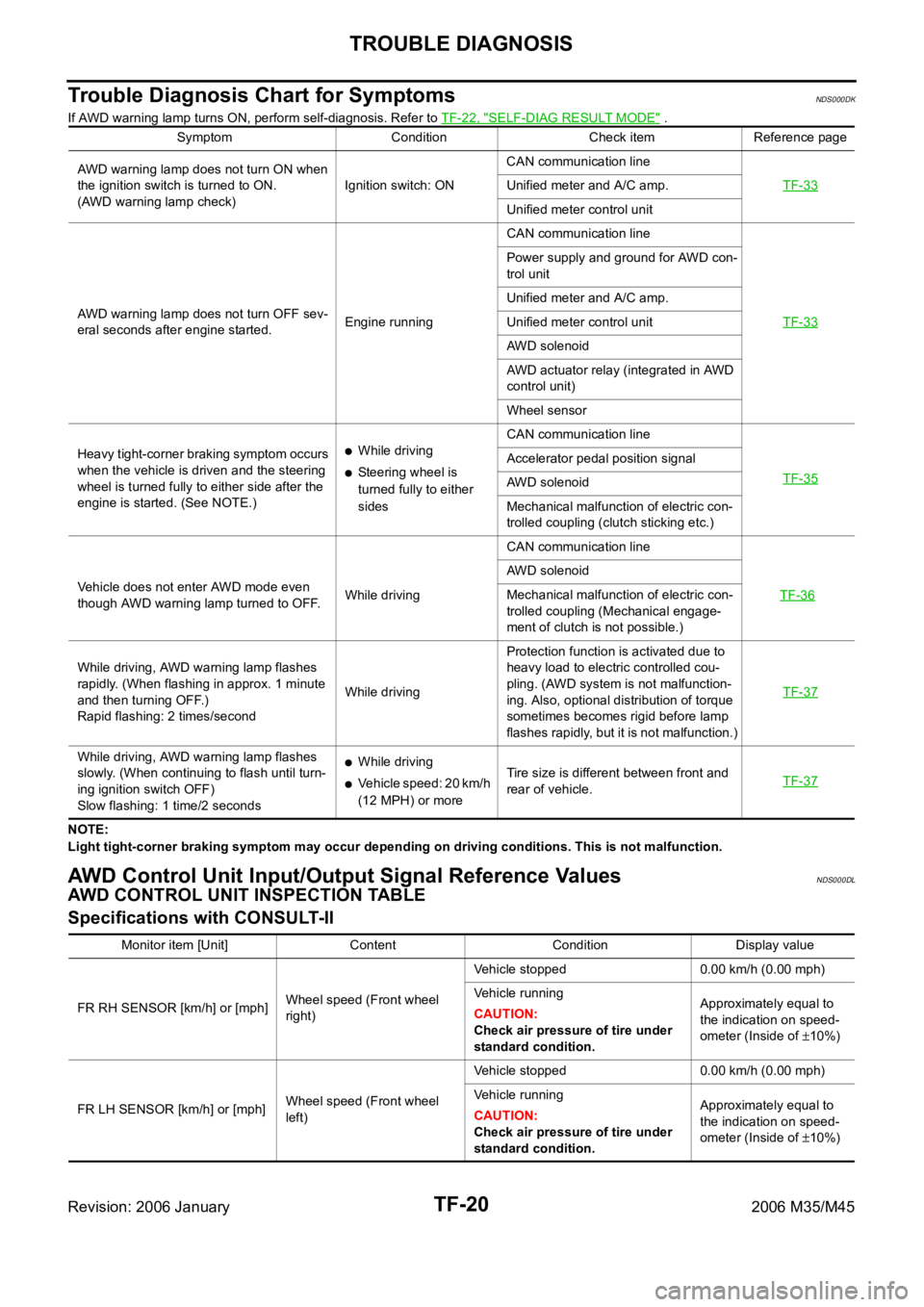
Trouble Diagnosis Chart for SymptomsNDS000DK
If AWD warning lamp turns ON, perform self-diagnosis. Refer to TF-22, "SELF-DIAG RESULT MODE" .
NOTE:
Light tight-corner braking symptom may occur depending on driving conditions. This is not malfunction.
AWD Control Unit Input/Output Signal Reference ValuesNDS000DL
AWD CONTROL UNIT INSPECTION TABLE
Specifications with CONSULT-II
Symptom Condition Check item Reference page
AWD warning lamp does not turn ON when
the ignition switch is turned to ON.
(AWD warning lamp check)Ignition switch: ONCAN communication line
TF-33
Unified meter and A/C amp.
Unified meter control unit
AWD warning lamp does not turn OFF sev-
eral seconds after engine started.Engine runningCAN communication line
TF-33
Power supply and ground for AWD con-
trol unit
Unified meter and A/C amp.
Unified meter control unit
AWD solenoid
AWD actuator relay (integrated in AWD
control unit)
Wheel sensor
Heavy tight-corner braking symptom occurs
when the vehicle is driven and the steering
wheel is turned fully to either side after the
engine is started. (See NOTE.)
While driving
Steering wheel is
turned fully to either
sidesCAN communication line
TF-35Accelerator pedal position signal
AWD solenoid
Mechanical malfunction of electric con-
trolled coupling (clutch sticking etc.)
Vehicle does not enter AWD mode even
though AWD warning lamp turned to OFF.While drivingCAN communication line
TF-36
AWD solenoid
Mechanical malfunction of electric con-
trolled coupling (Mechanical engage-
ment of clutch is not possible.)
While driving, AWD warning lamp flashes
rapidly. (When flashing in approx. 1 minute
and then turning OFF.)
Rapid flashing: 2 times/secondWhile drivingProtection function is activated due to
heavy load to electric controlled cou-
pling. (AWD system is not malfunction-
ing. Also, optional distribution of torque
sometimes becomes rigid before lamp
flashes rapidly, but it is not malfunction.)TF-37
While driving, AWD warning lamp flashes
slowly. (When continuing to flash until turn-
ing ignition switch OFF)
Slow flashing: 1 time/2 secondsWhile driving
Vehicle speed: 20 km/h
(12 MPH) or moreTire size is different between front and
rear of vehicle.TF-37
Monitor item [Unit] Content Condition Display value
FR RH SENSOR [km/h] or [mph]Wheel speed (Front wheel
right)Vehicle stopped 0.00 km/h (0.00 mph)
Vehicle running
CAUTION:
Check air pressure of tire under
standard condition.Approximately equal to
the indication on speed-
ometer (Inside of
10%)
FR LH SENSOR [km/h] or [mph]Wheel speed (Front wheel
left)Vehicle stopped 0.00 km/h (0.00 mph)
Vehicle running
CAUTION:
Check air pressure of tire under
standard condition.Approximately equal to
the indication on speed-
ometer (Inside of
10%)
Page 5533 of 5621
WT-8
ROAD WHEEL TIRE ASSEMBLY
Revision: 2006 January2006 M35/M45
If either residual imbalance value exceeds 7 g (0.25 oz), repeat installation procedures.
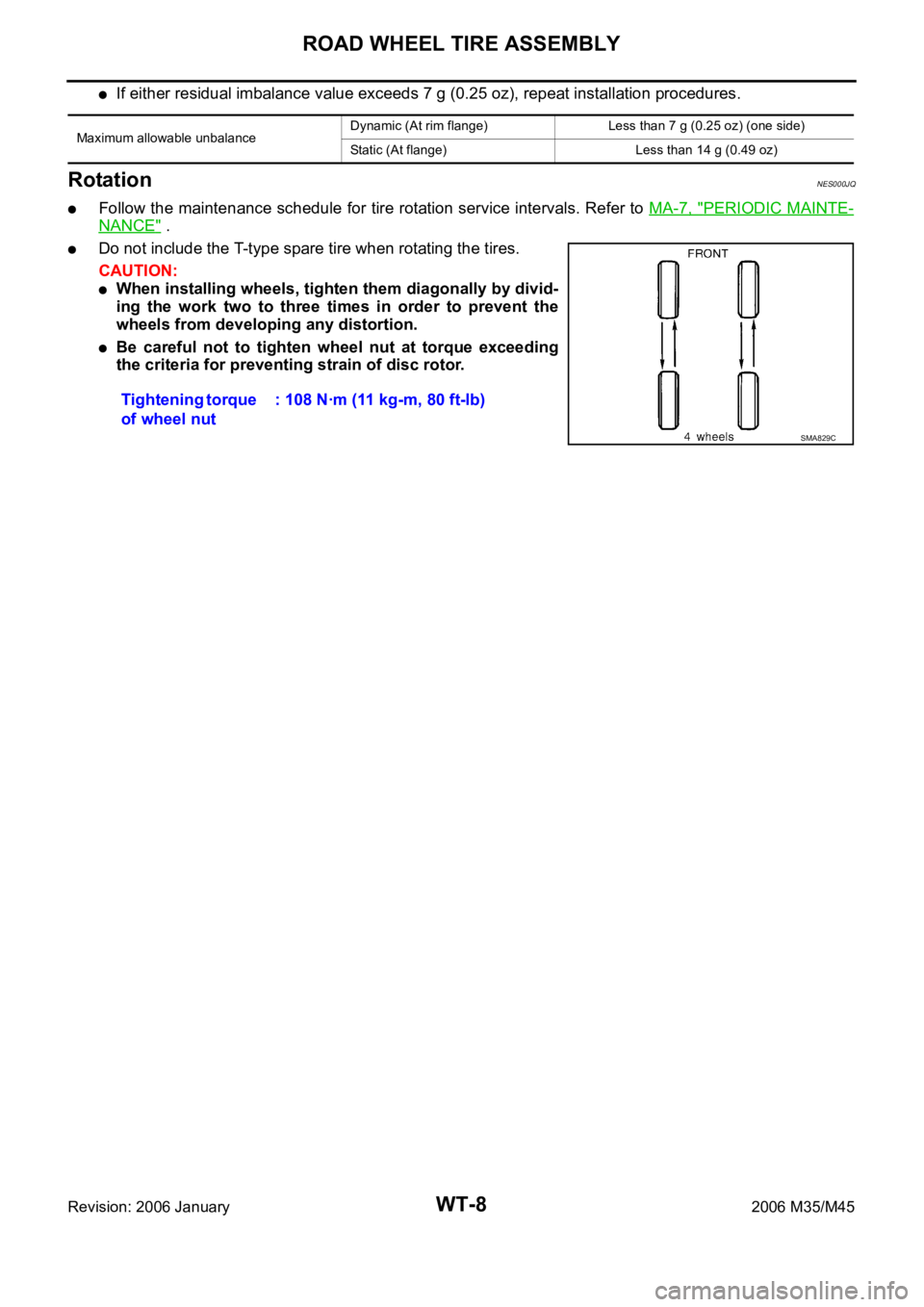
RotationNES000JQ
Follow the maintenance schedule for tire rotation service intervals. Refer to MA-7, "PERIODIC MAINTE-
NANCE" .
Do not include the T-type spare tire when rotating the tires.
CAUTION:
When installing wheels, tighten them diagonally by divid-
ing the work two to three times in order to prevent the
wheels from developing any distortion.
Be careful not to tighten wheel nut at torque exceeding
the criteria for preventing strain of disc rotor.
Maximum allowable unbalanceDynamic (At rim flange) Less than 7 g (0.25 oz) (one side)
Static (At flange) Less than 14 g (0.49 oz)
Tightening torque
of wheel nut: 108 Nꞏm (11 kg-m, 80 ft-lb)
SMA829C
Page 5565 of 5621
WT-40
REMOVAL AND INSTALLATION
Revision: 2006 January2006 M35/M45
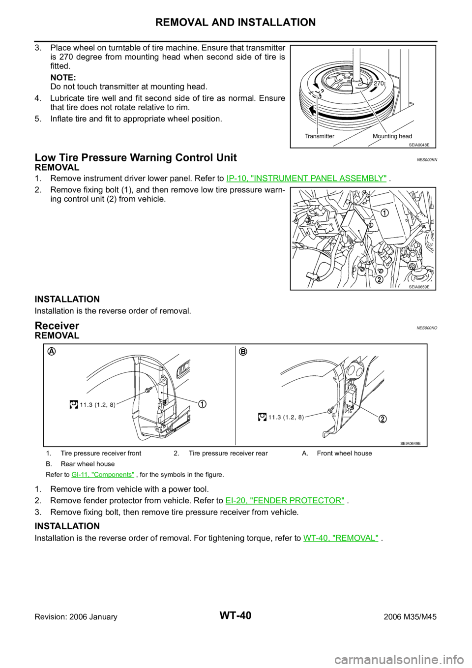
3. Place wheel on turntable of tire machine. Ensure that transmitter
is 270 degree from mounting head when second side of tire is
fitted.
NOTE:
Do not touch transmitter at mounting head.
4. Lubricate tire well and fit second side of tire as normal. Ensure
that tire does not rotate relative to rim.
5. Inflate tire and fit to appropriate wheel position.
Low Tire Pressure Warning Control UnitNES000KN
REMOVAL
1. Remove instrument driver lower panel. Refer to IP-10, "INSTRUMENT PANEL ASSEMBLY" .
2. Remove fixing bolt (1), and then remove low tire pressure warn-
ing control unit (2) from vehicle.
INSTALLATION
Installation is the reverse order of removal.
ReceiverNES000KO
REMOVAL
1. Remove tire from vehicle with a power tool.
2. Remove fender protector from vehicle. Refer to EI-20, "
FENDER PROTECTOR" .
3. Remove fixing bolt, then remove tire pressure receiver from vehicle.
INSTALLATION
Installation is the reverse order of removal. For tightening torque, refer to WT-40, "REMOVAL" .
SEIA0048E
SEIA0659E
1. Tire pressure receiver front 2. Tire pressure receiver rear A. Front wheel house
B. Rear wheel house
Refer to GI-11, "
Components" , for the symbols in the figure.
SEIA0649E